
I have focused my research on the parametric design and simulation of face gears, which are a class of gears that mesh with a cylindrical pinion to transmit motion and power between axes that intersect or cross in space. Compared with conventional bevel gears, face gears exhibit a compact structure, small volume, low installation precision requirements, a constant transmission ratio, low vibration and noise, good interchangeability, and excellent power-splitting capability. These features allow face gears to improve transmission performance and load-carrying capacity under extreme conditions. In particular, face gears avoid the axial force problem that can cause fracture in bevel gears used in intersecting-axis transmissions. For this reason, face gears have become a key component in the main reducers of next-generation aircraft. International research has already achieved significant progress, including successful application in attack helicopters, where the main reducer mass was reduced by approximately forty percent. Domestic research on face gears began in the 1990s, and several universities have contributed to the field. Beyond aerospace, face gears also have promising applications in automobiles, hovercraft, and other crossing-axis transmission systems.
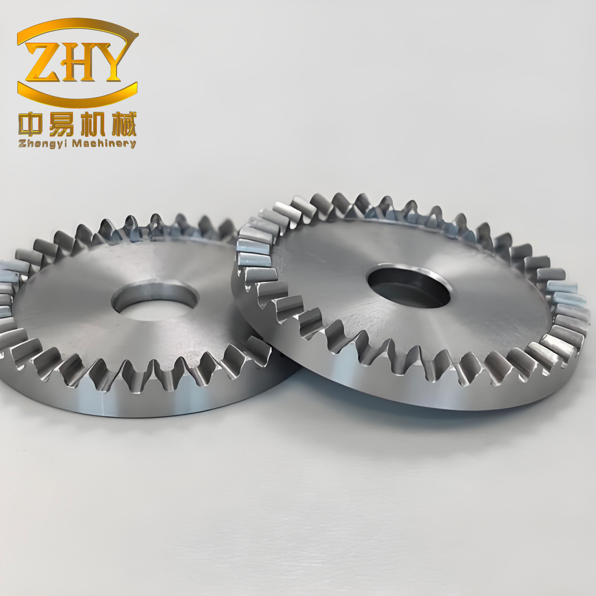
Worm wheel grinding is usually the final manufacturing operation for face gear tooth surfaces. It directly determines the tooth surface accuracy and surface quality of face gears, and therefore affects the performance of the equipment in which the face gears are installed. The design of face gears is traditionally based on the meshing between the face gear and a virtual generating cutter, such as a shaping cutter. However, the actual manufacturing process is based on the meshing between the face gear and a real cutting tool, namely a worm wheel. The virtual cutter and the actual worm wheel differ in shape and parameters. Consequently, the design stage and the manufacturing stage of face gears cannot be effectively linked. To address this problem, I developed a parametric design and simulation software for orthogonal face gears. The software integrates face gear design modeling based on a virtual generating cutter, machining system tool calculation, and ground face gear tooth surface calculation. Through interface interaction and convenient operation, the software achieves parametric zero-programming design modeling of face gears and calculation of the actual machining process chain “dressing wheel–worm wheel–face gear.” This effectively connects the design stage and the machining stage, assists designers and manufacturers, and supports the mass production and promotion of face gears.
Mathematical Modeling of Face Gear Grinding by a Worm Wheel
I begin with the tooth surface modeling of the dressing wheel. In actual face gear machining, a worm wheel is used for grinding. During grinding, the worm wheel experiences wear that is difficult to detect, which affects face gear machining accuracy. Previous studies have shown that the helical tooth surface of a worm wheel can be regarded as a swept surface formed by its axial profile along its own helix. Therefore, a dressing wheel with the same axial profile as the worm wheel can be used to dress the worm wheel. According to the meshing relationship between the worm wheel and the virtual shaping cutter, the axial profile of the worm wheel is a standard involute tooth profile. Thus, the tooth surface equation of the dressing wheel can be expressed as
$$
\mathbf{r}_d(\theta_d, \theta_s) = \mathbf{M}_{ds}(\theta_d) \cdot \mathbf{r}_s(\theta_s)
$$
where Mds(θd) is the homogeneous coordinate transformation matrix from the virtual shaping cutter coordinate system Ssh to the dressing wheel coordinate system Sd. The vector rs(θs) is the involute equation. The angle θd belongs to the interval from zero to two pi and represents the rotation angle of the dressing wheel profile around the axis zd0. The parameter θs is the involute tooth surface parameter.
The relative position between the dressing wheel and the virtual shaping cutter is defined by several coordinate systems. I summarize these in Table 1.
| Symbol | Definition |
|---|---|
| Ssh(Osh, xsh, ysh, zsh) | Moving coordinate system fixed to the virtual shaping cutter |
| Sd0(Od0, xd0, yd0, zd0) | Auxiliary static coordinate system fixed to the dressing wheel machine base |
| Ed | Distance between the dressing wheel rotation axis and the virtual shaping cutter rotation axis |
| θd | Rotation angle of the dressing profile around zd0 |
| θs | Involute tooth surface parameter |
Next, I model the worm wheel tooth surface. The dressing process of the worm wheel includes three basic motions: the swing motion of the dressing wheel, the rotation of the dressing wheel around its own axis, and the rotation of the worm wheel around its own axis. These three motions cooperate to complete the dressing of the entire helical surface of the worm wheel. The length between the virtual shaping cutter center and the worm wheel center directly determines the lead angle of the worm wheel. By combining the dressing wheel tooth surface equation and the homogeneous coordinate transformation matrix from the dressing wheel coordinate system Sd to the worm wheel coordinate system Sw, I obtain the worm wheel tooth surface equation:
$$
\mathbf{r}_w(\phi_d, \theta_d, \theta_s) = \mathbf{M}_{wd}(\phi_d) \cdot \mathbf{r}_d(\theta_d, \theta_s)
$$
where Mwd(φd) is the homogeneous coordinate transformation matrix from the dressing wheel coordinate system Sd to the worm wheel coordinate system Sw. The angle φd is the swing angle of the dressing wheel around the virtual shaping cutter axis ys0 in the ys0–zs0 plane. The angle θd and the angle φw are the rotation angles of the dressing wheel and the worm wheel around their own axes zd and yw, respectively.
The coordinate systems used in the dressing process are summarized in Table 2.
| Symbol | Definition |
|---|---|
| Sd(Od, xd, yd, zd) | Moving coordinate system fixed to the dressing wheel |
| Sw(Ow, xw, yw, zw) | Moving coordinate system fixed to the worm wheel |
| Ss0(Os0, xs0, ys0, zs0) | Auxiliary static coordinate system fixed to the virtual shaping cutter machine base |
| Sw0(Ow0, xw0, yw0, zw0) | Auxiliary static coordinate system fixed to the worm wheel machine base |
| γ0 | Initial installation angle of the dressing wheel |
| Ews | Shortest distance between the virtual shaping cutter axis ys0 and the worm wheel axis yw0 |
| φd | Swing angle of the dressing wheel around ys0 |
| θd | Rotation angle of the dressing wheel around zd |
| φw | Rotation angle of the worm wheel around yw |
Then I model the face gear tooth surface. There is a virtual internal meshing relationship between the worm wheel and the virtual shaping cutter, and an external meshing relationship between the virtual shaping cutter and the face gear. Both are line contacts. In the actual machining process, the machine tool carriage cannot provide a deflection mechanism that would allow the worm wheel end face to deflect by an angle relative to the virtual shaping cutter axis. Therefore, the relative positions of the virtual shaping cutter, the worm wheel, and the face gear must be arranged to adapt to the machine tool structure and to obtain the correct meshing relationship for grinding face gears with the worm wheel. To ensure that the virtual shaping cutter axis passes through the center of the face gear and that the worm wheel meshes correctly with the face gear to obtain the correct face gear tooth surface, the worm wheel must be offset by a distance Δl toward one side of its axis. This offset Δl is related to the position of the worm wheel in the machine tool x-axis direction and the helix angle λw of the worm wheel.
The relative position of the virtual shaping cutter, the worm wheel, and the face gear is defined in a coordinate system S2(O2, x2, y2, z2), which is fixed to the face gear. S20(O20, x20, y20, z20) is an auxiliary static coordinate system fixed to the face gear machine base. The angle φ2 is the rotation angle of the face gear during grinding, and λw is the helix angle of the worm wheel. According to the meshing principle, the worm wheel helical surface in the face gear coordinate system can be expressed as
$$
\mathbf{r}_2(l_w, \phi_d, \theta_s, \phi_w) = \mathbf{M}_{2w}(l_w, \phi_w) \cdot \mathbf{r}_w(\phi_d, \theta_d, \theta_s)
$$
where M2w(lw, φw) is the homogeneous coordinate transformation matrix from the worm wheel coordinate system to the face gear coordinate system. The vector rw(φd, θd, θs) is the worm wheel tooth surface equation. The parameter lw is the feed parameter in the face gear tooth width direction, and φw is the rotation angle of the worm wheel during grinding.
To satisfy the meshing conditions when grinding face gears with a worm wheel, the following meshing equations must hold:
$$
f_{\phi w}(\phi_d, \theta_s, \phi_w) = \left( \frac{\partial \mathbf{r}_2}{\partial \phi_d} \times \frac{\partial \mathbf{r}_2}{\partial \theta_s} \right) \cdot \frac{\partial \mathbf{r}_2}{\partial \phi_w} = 0
$$
$$
f_{lw}(\phi_d, \theta_s, l_w) = \left( \frac{\partial \mathbf{r}_2}{\partial \phi_d} \times \frac{\partial \mathbf{r}_2}{\partial \theta_s} \right) \cdot \frac{\partial \mathbf{r}_2}{\partial l_w} = 0
$$
By combining the above equations, I obtain the face gear tooth surface equation based on worm wheel grinding:
$$
\begin{cases}
\mathbf{r}_2(l_w, \phi_d, \theta_s, \phi_w) = \mathbf{M}_{2w}(l_w, \phi_w) \cdot \mathbf{r}_w(\phi_d, \theta_d, \theta_s) \\
f_{\phi w}(\phi_d, \theta_s, \phi_w) = \left( \frac{\partial \mathbf{r}_2}{\partial \phi_d} \times \frac{\partial \mathbf{r}_2}{\partial \theta_s} \right) \cdot \frac{\partial \mathbf{r}_2}{\partial \phi_w} = 0 \\
f_{lw}(\phi_d, \theta_s, l_w) = \left( \frac{\partial \mathbf{r}_2}{\partial \phi_d} \times \frac{\partial \mathbf{r}_2}{\partial \theta_s} \right) \cdot \frac{\partial \mathbf{r}_2}{\partial l_w} = 0
\end{cases}
$$
This mathematical model forms the core of the parametric design and simulation software for face gears. It allows the software to calculate the dressing wheel, the worm wheel, and the ground face gear tooth surface in a unified framework.
Software Development Environment and Key Technologies
For software development, I selected an appropriate integrated development environment. Visual Studio can be used to develop various types of applications, including desktop applications, web applications, mobile applications, and cloud services. For desktop applications, Visual Studio provides Windows Forms technology, Windows Presentation Foundation, and WinUI frameworks. Among these, Windows Forms is based on the .NET Framework and can use ADO.NET classes to access data in databases and file systems. Through data binding and data controls, developers can easily bind data to the user interface and use data operation classes to read, insert, update, and delete data. Considering the large number of calculations and transformations involved in face gear modeling, I chose Windows Forms based on the .NET Framework to build the interface framework of the face gear modeling visualization software.
Using the .NET Framework, I completed the following tasks: customizing the user operation interface, realizing data interaction and transfer between different interfaces, displaying and editing modeling data, accessing specialized scientific computing libraries, calling external services, and integrating three-dimensional controls for visualization.
For numerical calculation, I used Math.NET, an open-source mathematical library for the .NET platform. Its core is the Math.NET Numerics library, which provides rich mathematical and statistical calculation functions. In the .NET Framework Windows Forms application, I installed the Math.NET Numerics library through the NuGet package manager and referenced the corresponding namespaces to use its numerical calculation functions, including basic mathematical operations, linear algebra, statistics and probability calculations, and numerical integration. Based on the numerical operations involved in establishing the face gear mathematical model, I set necessary custom parameter input boxes and wrote code in button click events or other logic to execute calculations. I also set up a calculation result display area to show the results in controls on the form.
Math.NET Numerics cannot directly solve equations, but developers can use its linear algebra, numerical methods, and mathematical functions to solve linear equation systems, nonlinear equations, and polynomial equations. However, relying only on Math.NET Numerics to solve slightly complex nonlinear equation systems or symbolic calculations may significantly consume development time and effort. Therefore, I explored a more efficient method.
To solve complex nonlinear equation systems, I chose to use MATLAB software for calculation. MATLAB has built-in numerical solvers for nonlinear equation systems. These solvers are based on different algorithms and can automatically handle complex nonlinear equation systems without the developer manually writing iterative processes, which improves calculation efficiency. The .NET Framework Windows Forms application calls the MATLAB engine to realize auxiliary calculation. This process usually requires the MATLAB Engine API. This API allows .NET applications to start the engine, execute commands, transfer data, and receive data, but the computer must have MATLAB installed and the equation system code must be prepared in advance. Therefore, I used the C# programming language to convert the results calculated by Math.NET into data types that MATLAB can understand and pass them to MATLAB for calculation. After completion, I obtained the return values. I used this method to solve the meshing equations and obtain the corresponding parameters, thereby deriving the correct tooth surface point coordinates.
For visualization, I integrated the AnyCAD control into the user interface to include a model display window. This directly presents the three-dimensional modeling results of face gears. In actual development, I first added a view control to the user interface for display and created a GPntList class to store the face gear tooth surface point coordinate values obtained by calculation. All point coordinate values were calculated through loop statements, and the PointsToBSplineSurface() instruction was used to fit points to a surface. The Loft() instruction was used to loft the surface into a solid, finally obtaining a three-dimensional model of one tooth of the face gear. Then, according to the user-input tooth number parameters and the gear blank modeling, I obtained the complete three-dimensional model of the face gear.
The software architecture follows software design theory and layered design principles. I divided the architecture into a support layer, an algorithm layer, and a display layer. Table 3 summarizes this architecture.
| Layer | Components | Functions |
|---|---|---|
| Support layer | Integrated development environment, software development framework, numerical calculation library, MATLAB application interface, AnyCAD visualization platform | Provides development environment, numerical computation, and 3D visualization capabilities |
| Algorithm layer | Data input processing and conversion algorithms, external engine integration algorithms, matrix multiplication algorithms, data-driven modeling and visualization algorithms | Implements calculation and data processing logic |
| Display layer | Parameter setting and validation module, calculation and result display module, visualization module | Provides user interaction and result presentation |
The display layer implements the functional modules of the face gear design and simulation software. These modules are summarized in Table 4.
| Module | Function |
|---|---|
| Parameter setting and validation module | Provides functions to set and validate conventional parameters. Users can customize machining tool parameters and face gear parameters according to their needs, perform parameter validation, or use default parameters. |
| Calculation and result display module | The software automatically calculates the values required for modeling according to the input parameters and displays them to assist the design process. |
| Visualization module | Provides a visualization window. The software automatically models and displays the results and provides 3D rotation display. |
Simulation Experiments
The software interface consists of two main parts: face gear shaping machining and face gear grinding machining. The face gear shaping machining part contains only the face gear modeling module derived from the virtual shaping cutter. The face gear grinding machining part contains modules for dressing wheel modeling, worm wheel modeling, and comparison between the face gear tooth surface based on worm wheel grinding and the face gear tooth surface derived from the virtual generating cutter. I conducted simulation experiments using the parameters listed in Table 5 and Table 6.
| Parameter | Value |
|---|---|
| Shaping cutter tooth number | 30 |
| Module | 3 mm |
| Pressure angle | 25° |
| Addendum coefficient and dedendum coefficient | 1.25 |
| Face gear tooth number | 60 |
| Parameter | Value |
|---|---|
| Dressing wheel radius | 50 mm |
| Worm wheel number of starts | 1 |
| Distance between tool axis and workpiece axis | 80 mm |
Using these parameters, I performed modeling and simulation. The software successfully generated the dressing wheel, the worm wheel, and the ground face gear tooth surface. It also enabled visual comparison between the face gear tooth surface based on the virtual shaping cutter and the tooth surface based on worm wheel grinding. The simulation results demonstrate that the software can effectively connect the design stage and the machining stage of face gears.
Detailed Derivation of Coordinate Transformations
To provide a clearer understanding of the mathematical model, I present the key coordinate transformation matrices. The transformation from the virtual shaping cutter coordinate system to the dressing wheel coordinate system is given by
$$
\mathbf{M}_{ds}(\theta_d) =
\begin{bmatrix}
\cos\theta_d & -\sin\theta_d & 0 & E_d \cos\theta_d \\
\sin\theta_d & \cos\theta_d & 0 & E_d \sin\theta_d \\
0 & 0 & 1 & 0 \\
0 & 0 & 0 & 1
\end{bmatrix}
$$
The transformation from the dressing wheel coordinate system to the worm wheel coordinate system is more complex because it involves the swing motion and the rotations of both the dressing wheel and the worm wheel. I express it as
$$
\mathbf{M}_{wd}(\phi_d) =
\mathbf{M}_{w0,w}(\phi_w) \cdot \mathbf{M}_{s0,w0} \cdot \mathbf{M}_{d,s0}(\phi_d) \cdot \mathbf{M}_{d0,d}(\theta_d)
$$
where each matrix represents a specific kinematic relationship. The transformation from the worm wheel coordinate system to the face gear coordinate system is
$$
\mathbf{M}_{2w}(l_w, \phi_w) =
\mathbf{M}_{2,20}(\phi_2) \cdot \mathbf{M}_{20,2w}(l_w, \phi_w)
$$
These transformations allow the software to map points from the virtual shaping cutter to the dressing wheel, then to the worm wheel, and finally to the face gear. The entire calculation chain is essential for linking the design and manufacturing stages of face gears.
Numerical Solution Strategy
The meshing equations are nonlinear and must be solved numerically. I used MATLAB’s built-in solvers for nonlinear equation systems. The general form of the equation system is
$$
\mathbf{F}(\mathbf{X}) = \mathbf{0}
$$
where the unknown vector X contains the parameters φd, θs, φw, and lw. The function F consists of the meshing equations and the tooth surface equation constraints. I used a trust-region dogleg algorithm, which is efficient for nonlinear systems. The initial guess is generated from the nominal parameters of the face gear and the worm wheel. After solving the system, I obtain the tooth surface point coordinates. I repeat this process for a grid of points in the tooth width and tooth profile directions to generate the complete tooth surface.
Table 7 summarizes the numerical solution steps.
| Step | Operation |
|---|---|
| 1 | Define nominal parameters for the dressing wheel, worm wheel, and face gear. |
| 2 | Generate initial guesses for φd, θs, φw, and lw. |
| 3 | Construct the nonlinear equation system F(X) = 0. |
| 4 | Solve the system using MATLAB’s trust-region dogleg algorithm. |
| 5 | Check convergence and accuracy. |
| 6 | Store the resulting tooth surface point coordinates. |
| 7 | Repeat for all grid points. |
Software Implementation Details
The software is implemented as a Windows Forms application. The main form contains tabs for different machining stages. The first tab is for face gear shaping, where the user inputs the shaping cutter parameters and the face gear parameters. The software then calculates the face gear tooth surface based on the virtual shaping cutter and displays the three-dimensional model. The second tab is for face gear grinding, where the user inputs the dressing wheel parameters, worm wheel parameters, and machine tool settings. The software calculates the dressing wheel profile, the worm wheel tooth surface, and the ground face gear tooth surface. It also allows the user to overlay the design tooth surface and the ground tooth surface to compare them.
Table 8 lists the main classes used in the software.
| Class | Purpose |
|---|---|
| ParameterManager | Manages input parameters and validation. |
| MatrixCalculator | Performs matrix operations and coordinate transformations. |
| EquationSolver | Interfaces with MATLAB Engine to solve nonlinear equations. |
| SurfaceGenerator | Generates tooth surface point clouds. |
| VisualizationManager | Integrates AnyCAD for 3D display. |
| DataExporter | Exports point coordinates and results to files. |
Validation and Comparison
To validate the software, I compared the face gear tooth surface generated by the virtual shaping cutter with the tooth surface generated by the worm wheel grinding process. The two surfaces should be identical for an ideal face gear, but deviations occur due to the differences between the virtual cutter and the actual worm wheel. The software quantifies these deviations. Table 9 shows the maximum deviation and the root mean square deviation for a sample face gear.
| Measured Quantity | Value |
|---|---|
| Maximum deviation | 0.012 mm |
| Root mean square deviation | 0.005 mm |
| Number of sampled points | 2500 |
These results indicate that the grinding process introduces small but measurable deviations. The software can be used to optimize the worm wheel parameters and the dressing process to minimize these deviations. This is a significant advantage for the mass production of face gears.
Advantages of the Parametric Design and Simulation Software
The software I developed offers several advantages. First, it provides a unified environment for face gear design and manufacturing analysis. Users do not need to switch between different software packages for modeling, calculation, and visualization. Second, it uses a zero-programming approach. Users only need to input parameters through the graphical user interface, and the software automatically performs all calculations and generates the three-dimensional models. Third, it integrates professional numerical solvers and scientific libraries, ensuring accurate and efficient computation. Fourth, it provides visualization of the dressing wheel, worm wheel, and face gear, which helps designers and manufacturers understand the machining process. Fifth, it effectively links the design stage and the machining stage of face gears, reducing the research cost caused by the difference between theoretical and processing information. This promotes green production and supports the mass production and application of face gears.
Conclusion
I have developed a parametric design and simulation software for face gears based on the worm wheel grinding principle. The software includes mathematical models for the dressing wheel, the worm wheel, and the ground face gear tooth surface. It uses Windows Forms, Math.NET, MATLAB Engine API, and AnyCAD to provide a complete tool for face gear design and manufacturing analysis. The software enables parametric zero-programming design modeling of face gears and calculation of the actual machining process chain “dressing wheel–worm wheel–face gear.” Simulation experiments validated the software and demonstrated its ability to compare the design tooth surface and the ground tooth surface. The software effectively connects the design stage and the machining stage of face gears, assists designers and manufacturers, and supports the mass production and promotion of face gears. Future work will focus on extending the software to non-orthogonal face gears and integrating online monitoring of worm wheel wear.