
In this study, I investigate the nonlinear vibration characteristics of a non-orthogonal and asymmetric face gear transmission system, with particular attention to how the excitation frequency governs the transition between periodic, quasi-periodic, and chaotic motions. The system combines two distinctive features: a shaft angle that is not equal to 90 degrees, and gear teeth whose two flanks are generated with different pressure angles. These features make the transmission suitable for high-speed and heavy-load applications, but they also introduce complex dynamic behaviors. I construct a nonlinear dynamic model of the system, solve the governing differential equations using the Runge–Kutta method, and analyze the resulting time-domain histories, spatial frequency spectra, phase portraits, Poincaré sections, and bifurcation diagrams. The results show that the system exhibits rich nonlinear phenomena and that the pressure angle and shaft angle have a strong influence on the stability of the chaotic state. In particular, I find that decreasing the pressure angle or increasing the shaft angle within a certain range reduces the vibration displacement in the chaotic regime, which is beneficial for improving the stability of the transmission.
1. Introduction
Face gears are a special class of gears that transmit motion between intersecting axes. Unlike conventional cylindrical gears, face gears mate with a cylindrical pinion and offer advantages such as high contact ratio, compact structure, and large gear ratio. When the shaft angle is not 90 degrees, the system is called a non-orthogonal face gear drive. When the two flanks of the gear teeth have different pressure angles, the system is called an asymmetric face gear drive. The combination of these two features yields a non-orthogonal and asymmetric face gear transmission system. Such systems are increasingly used in aviation engines, marine propulsion systems, and rotorcraft, where high transmission efficiency and reliability are required.
Despite the increasing use of face gears, the nonlinear dynamics of non-orthogonal and asymmetric face gear systems have not been sufficiently explored. Most existing studies focus on orthogonal face gears or symmetric gear teeth. The influence of pressure angle and shaft angle on the nonlinear vibration characteristics remains unclear. In this work, I aim to fill this gap by developing a comprehensive nonlinear dynamic model of a non-orthogonal and asymmetric face gear transmission system. I consider the effects of backlash, time-varying mesh stiffness, transmission error, and support stiffness and damping. I then solve the system of differential equations and analyze the dynamic responses under different pressure angles and shaft angles.
The main contributions of this study are as follows. First, I establish a nonlinear dynamic model that accounts for the non-orthogonal geometry and the asymmetric tooth flanks of face gears. Second, I derive the dimensionless form of the governing equations, which facilitates numerical solution. Third, I systematically investigate the influence of excitation frequency, pressure angle, and shaft angle on the nonlinear dynamic behavior. Fourth, I identify conditions under which the chaotic vibration can be reduced, thereby improving the stability of the face gear transmission.
2. System Description and Dynamic Modeling
The non-orthogonal and asymmetric face gear transmission system considered here consists of a cylindrical pinion, denoted as gear 1, and a face gear, denoted as gear 2. The shaft angle between the two axes is not equal to 90 degrees. The two flanks of each tooth are generated with different pressure angles, so the gear behaves differently in forward and reverse rotation. The system is supported by bearings that provide stiffness and damping in the x, y, and z directions. The mesh between the pinion and the face gear is modeled as a time-varying stiffness and damping element along the line of action. A transmission error is also included to account for manufacturing and assembly errors.
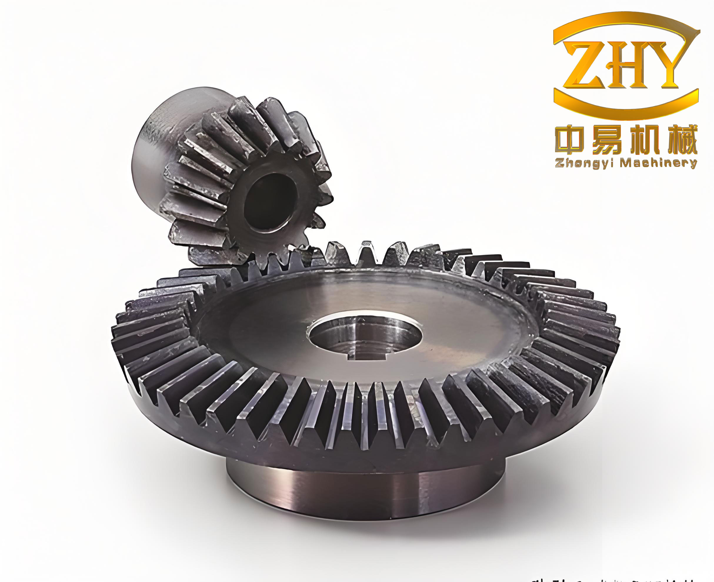
Figure 1 shows a schematic of the non-orthogonal and asymmetric face gear transmission system. The pinion is connected to the input shaft, and the face gear is connected to the output shaft. The shaft angle is denoted by δ. The pressure angle is denoted by α. The helix angle is denoted by β. The dynamic model includes the translational motions of both gears in three orthogonal directions, as well as the torsional motions. The mesh force acts along the line of action, which depends on the pressure angle and the shaft angle.
Table 1 lists the basic parameters of the system. These parameters are used in the numerical simulations presented in later sections.
| Parameter | Gear 1 (pinion) | Gear 2 (face gear) |
|---|---|---|
| Number of teeth | 23 | 85 |
| Mass (kg) | 3 | 12 |
| Module (mm) | 4 | 4 |
| Helix angle (deg) | 20 | 20 |
| Rotational inertia (kg·m²) | 0.005 | 2.270 |
| Support stiffness (N/m) | \(1\times 10^8\) | \(6\times 10^8\) |
| Support damping (N·s/m) | \(6\times 10^3\) | \(1\times 10^4\) |
The gear mesh is characterized by a time-varying mesh stiffness \(k(t)\) and a constant mesh damping \(c_n\). The mesh force also depends on the backlash function \(f(P)\), where \(P\) is the relative displacement along the line of action. The backlash function is nonlinear and is defined as
$$
f(P) = \begin{cases}
P – b, & P > b, \\
0, & -b \le P \le b, \\
P + b, & P < -b,
\end{cases}
$$
where \(b\) is half of the backlash. This piecewise nonlinear function captures the loss of contact when the relative displacement exceeds the backlash. In the dimensionless formulation, the backlash is normalized to unity.
The transmission error \(e_n(t)\) is assumed to be harmonic and is given by
$$
e_n(t) = e_0 \sin(\Omega_h t),
$$
where \(e_0\) is the amplitude of the transmission error and \(\Omega_h\) is the mesh frequency. The mesh frequency is related to the rotational speed of the pinion.
3. Equations of Motion
I derive the equations of motion for the non-orthogonal and asymmetric face gear transmission system using Newton’s second law. The pinion and the face gear are treated as rigid bodies with translational and rotational degrees of freedom. The mesh force acts along the line of action, which is determined by the pressure angle and the shaft angle. The support bearings provide stiffness and damping in the x, y, and z directions.
Let \(X_i, Y_i, Z_i\) denote the translational displacements of gear \(i\) in the x, y, and z directions, respectively, where \(i=1\) for the pinion and \(i=2\) for the face gear. Let \(\phi_i\) denote the angular displacement of gear \(i\). The equations of motion for the pinion are
$$
\begin{aligned}
M_1 \ddot{X}_1 + c_{x1} \dot{X}_1 + k_{x1} X_1 &= -F_n \cos\alpha \sin\beta, \\
M_1 \ddot{Y}_1 + c_{y1} \dot{Y}_1 + k_{y1} Y_1 &= -F_n \cos\alpha \cos\beta, \\
M_1 \ddot{Z}_1 + c_{z1} \dot{Z}_1 + k_{z1} Z_1 &= -F_n \sin\alpha.
\end{aligned}
$$
Similarly, the equations of motion for the face gear are
$$
\begin{aligned}
M_2 \ddot{X}_2 + c_{x2} \dot{X}_2 + k_{x2} X_2 &= F_n \cos\alpha \sin\beta \sin(90^\circ – \delta), \\
M_2 \ddot{Y}_2 + c_{y2} \dot{Y}_2 + k_{y2} Y_2 &= F_n \cos\alpha \cos\beta, \\
M_2 \ddot{Z}_2 + c_{z2} \dot{Z}_2 + k_{z2} Z_2 &= F_n \sin\alpha \cos(90^\circ – \delta).
\end{aligned}
$$
Here, \(M_i\) is the mass of gear \(i\), \(c_{ji}\) and \(k_{ji}\) are the damping and stiffness coefficients in the \(j\)-th direction for gear \(i\), and \(F_n\) is the normal mesh force. The normal mesh force is given by
$$
F_n = k(t) f(P) + c_n \dot{P} + F_m,
$$
where \(k(t)\) is the time-varying mesh stiffness, \(c_n\) is the mesh damping, \(F_m\) is the mean mesh force, and \(P\) is the relative displacement along the line of action. The relative displacement \(P\) is related to the translational and rotational displacements by
$$
P = (X_1 – X_2) \cos\alpha \sin\beta + (Y_1 – Y_2) \cos\alpha \cos\beta + (Z_1 – Z_2) \sin\alpha + r_1 \phi_1 – r_2 \phi_2 – e_n(t),
$$
where \(r_1\) and \(r_2\) are the base circle radii of the pinion and face gear, respectively. The rotational motions are governed by
$$
\begin{aligned}
T_1 &= (F_{1a} + F_{1b}) r_1 + I_1 \ddot{\phi}_1, \\
T_2 &= F_2 r_2 – I_2 \ddot{\phi}_2,
\end{aligned}
$$
where \(T_1\) is the driving torque, \(T_2\) is the load torque, \(I_1\) and \(I_2\) are the rotational inertias, and \(F_{1a}\) and \(F_{1b}\) are the mean and fluctuating components of the mesh force. The equivalent mass of the gear pair is defined as
$$
M_e = \frac{I_1 I_2}{I_1 r_2^2 + I_2 r_1^2}.
$$
By combining the translational and rotational equations, the equation of motion along the line of action can be written as
$$
\begin{aligned}
M_e \ddot{P} &= M_e \ddot{Y}_1 \cos\alpha \cos\beta – M_e \ddot{Y}_2 \cos\alpha \cos\beta \\
&\quad + M_e \ddot{X}_1 \cos\alpha \sin\beta – M_e \ddot{X}_2 \cos\alpha \sin\beta \sin(90^\circ – \delta) \\
&\quad + M_e \ddot{Z}_1 \sin\alpha – M_e \ddot{Z}_2 \sin\alpha \cos(90^\circ – \delta) \\
&\quad – k(t) f(P) \cos\alpha + c_n \dot{P} \cos\alpha + F_m \cos\alpha + M_e \ddot{e}_n(t).
\end{aligned}
$$
This equation is the central dynamic equation of the system. It includes the effects of backlash, time-varying mesh stiffness, mesh damping, and transmission error. The coupling between the translational and rotational motions is evident through the geometric terms involving the pressure angle and the shaft angle.
4. Dimensionless Formulation
Because the physical quantities in the equations of motion vary by several orders of magnitude, I introduce dimensionless variables to improve the numerical stability and to facilitate the analysis. The dimensionless displacements are defined as
$$
x_i = \frac{X_i}{b_n}, \quad y_i = \frac{Y_i}{b_n}, \quad z_i = \frac{Z_i}{b_n}, \quad \lambda = \frac{P}{b_n},
$$
where \(b_n\) is the characteristic backlash. The dimensionless time is defined as
$$
\tau = \omega_n t,
$$
where \(\omega_n\) is the natural frequency of the system. The dimensionless damping and stiffness coefficients are
$$
\zeta_n = \frac{c_n}{2 M_e \Omega_h / \omega_n}, \quad
\kappa_{ij} = \frac{k_{ij}}{M_i (\Omega_h / \omega_n)^2}, \quad
\kappa_{ni} = \frac{k(t)}{M_i (\Omega_h / \omega_n)^2} = \frac{M_e}{M_i} \kappa(\tau),
$$
where \(\Omega_h\) is the mesh frequency. The dimensionless mesh force amplitude is
$$
f_m = \frac{F_m \cos\alpha}{b_n M_e (\Omega_h / \omega_n)^2}.
$$
Using these definitions, the dimensionless equations of motion for the pinion become
$$
\begin{aligned}
\ddot{x}_1(\tau) + 2\zeta_{x1} \dot{x}_1(\tau) + 2\cos\alpha \sin\beta \zeta_{n1} \dot{\lambda}(\tau) + \kappa_{x1} x_1(\tau) + \cos\alpha \sin\beta \kappa_{n1} l(\lambda) &= 0, \\
\ddot{y}_1(\tau) + 2\zeta_{y1} \dot{y}_1(\tau) + 2\cos\alpha \cos\beta \zeta_{n1} \dot{\lambda}(\tau) + \kappa_{y1} y_1(\tau) + \cos\alpha \cos\beta \kappa_{n1} l(\lambda) &= 0, \\
\ddot{z}_1(\tau) + 2\zeta_{z1} \dot{z}_1(\tau) + 2\sin\alpha \zeta_{n1} \dot{\lambda}(\tau) + \kappa_{z1} z_1(\tau) + \sin\alpha \kappa_{n1} l(\lambda) &= 0.
\end{aligned}
$$
The dimensionless equations for the face gear are
$$
\begin{aligned}
\ddot{x}_2(\tau) + 2\zeta_{x2} \dot{x}_2(\tau) – 2\cos\alpha \sin\beta \sin(90^\circ – \delta) \zeta_{n2} \dot{\lambda}(\tau) + \kappa_{x2} x_2(\tau) – \cos\alpha \sin\beta \sin(90^\circ – \delta) \kappa_{n2} l(\lambda) &= 0, \\
\ddot{y}_2(\tau) + 2\zeta_{y2} \dot{y}_2(\tau) – 2\cos\alpha \cos\beta \zeta_{n2} \dot{\lambda}(\tau) + \kappa_{y2} y_2(\tau) – \cos\alpha \cos\beta \kappa_{n2} l(\lambda) &= 0, \\
\ddot{z}_2(\tau) + 2\zeta_{z2} \dot{z}_2(\tau) + \kappa_{z2} z_2(\tau) – 2\sin\alpha \cos(90^\circ – \delta) \zeta_{n2} \dot{\lambda}(\tau) – \sin\alpha \cos(90^\circ – \delta) \kappa_{n2} l(\lambda) &= 0.
\end{aligned}
$$
The dimensionless equation for the relative displacement along the line of action is
$$
\begin{aligned}
\ddot{\lambda}(\tau) &+ 2\cos\alpha \zeta_n \dot{\lambda}(\tau) + \cos\alpha \kappa(\tau) l(\lambda) \\
&- \cos\alpha \sin\beta \ddot{x}_1(\tau) + \cos\alpha \sin\beta \sin(90^\circ – \delta) \ddot{x}_2(\tau) \\
&- \cos\alpha \cos\beta \ddot{y}_1(\tau) + \cos\alpha \cos\beta \ddot{y}_2(\tau) \\
&- \sin\alpha \ddot{z}_1(\tau) + \sin\alpha \cos(90^\circ – \delta) \ddot{z}_2(\tau) – f_m = 0.
\end{aligned}
$$
In these equations, \(l(\lambda)\) is the dimensionless backlash function, defined as
$$
l(\lambda) = \begin{cases}
\lambda – 1, & \lambda > 1, \\
0, & -1 \le \lambda \le 1, \\
\lambda + 1, & \lambda < -1.
\end{cases}
$$
The dimensionless formulation reduces the number of independent parameters and makes the numerical integration more efficient. I solve the above system of differential equations using the fourth-order Runge–Kutta method. The time step is chosen small enough to capture the high-frequency components of the response. The initial conditions are set to zero displacement and zero velocity, and the first few hundred cycles are discarded to eliminate transient effects.
5. Nonlinear Dynamic Responses
In this section, I present the nonlinear dynamic responses of the non-orthogonal and asymmetric face gear transmission system. I focus on the influence of the excitation frequency, the pressure angle, and the shaft angle. The excitation frequency is nondimensionalized as \(\omega_e = \Omega_h / \omega_n\). The pressure angle \(\alpha\) is varied from 15° to 30°, and the shaft angle \(\delta\) is varied from 0° to 90°. For each case, I compute the time-domain history, the spatial frequency spectrum, the phase portrait, the Poincaré section, and the bifurcation diagram.
5.1 Effect of Pressure Angle
I first fix the shaft angle at 60° and investigate the effect of the pressure angle. Four values of the pressure angle are considered: 15°, 20°, 25°, and 30°. The excitation frequency is used as the bifurcation parameter. The dynamic responses are analyzed for three representative excitation frequencies: \(\omega_e = 1.82\), \(\omega_e = 1.85\), and \(\omega_e = 2.04\).
At \(\omega_e = 1.82\), the phase portrait shows a single closed loop, and the Poincaré section consists of a single point. This indicates that the system is in a stable single-periodic motion. At \(\omega_e = 1.85\), the phase portrait exhibits two closed loops, and the Poincaré section shows two distinct point sets. The system is in a period-doubling state. At \(\omega_e = 2.04\), the phase portrait becomes a series of interlaced closed loops, and the Poincaré section displays a large number of scattered points. The system is in a chaotic state.
Table 2 summarizes the dynamic states observed at different excitation frequencies and pressure angles. The results show that the transition from periodic to chaotic motion occurs at slightly different frequencies depending on the pressure angle. However, the general trend is consistent: as the pressure angle increases, the vibration displacement in the chaotic state also increases.
| Pressure angle (deg) | \(\omega_e = 1.82\) | \(\omega_e = 1.85\) | \(\omega_e = 2.04\) |
|---|---|---|---|
| 15 | Single-periodic | Period-doubling | Chaotic |
| 20 | Single-periodic | Period-doubling | Chaotic |
| 25 | Single-periodic | Period-doubling | Chaotic |
| 30 | Single-periodic | Period-doubling | Chaotic |
The time-domain histories provide further insight. At \(\omega_e = 1.85\), the time-domain waveforms are periodic and stable, which is consistent with the period-doubling state. At \(\omega_e = 2.10\), the waveforms become irregular and non-repeating, which is characteristic of chaos. As the pressure angle increases from 15° to 30°, the amplitude of the chaotic vibration increases. This means that a smaller pressure angle is beneficial for reducing the chaotic vibration of the face gears.
The spatial frequency spectra reveal the frequency content of the response. In the single-periodic state, the dominant frequency is near 1.0. In the period-doubling state, two dominant peaks appear near 0.5 and 1.0, with the peak at 0.5 being more prominent. In the chaotic state, many small-amplitude harmonics appear, mostly concentrated around 0.5. These spectral features are consistent with the bifurcation scenario.
The bifurcation diagrams with the excitation frequency as the bifurcation parameter show that the system undergoes a period-doubling bifurcation at \(\omega_e \approx 1.84\) and enters chaos at \(\omega_e \approx 2.02\). As the pressure angle increases, the bifurcation points shift slightly, and the width of the chaotic band increases. The vibration displacement in the chaotic state increases with the pressure angle. Therefore, reducing the pressure angle can improve the stability of the non-orthogonal and asymmetric face gear transmission system.
5.2 Effect of Shaft Angle
Next, I fix the pressure angle at 20° and investigate the effect of the shaft angle. Four values of the shaft angle are considered: 0°, 30°, 60°, and 90°. The excitation frequency is again used as the bifurcation parameter. The dynamic responses are analyzed at \(\omega_e = 1.82\), \(\omega_e = 1.85\), and \(\omega_e = 2.01\).
At \(\omega_e = 1.82\), the phase portrait is a single closed curve, and the Poincaré section is a single point, indicating single-periodic motion. At \(\omega_e = 1.85\), the phase portrait shows two closed curves, and the Poincaré section shows two point sets, indicating period-doubling. At \(\omega_e = 2.01\), the phase portrait becomes a series of closed curves, and the Poincaré section shows a scattered set of points, indicating chaos. These observations are consistent with the results for different pressure angles.
Table 3 summarizes the dynamic states at different shaft angles and excitation frequencies. The transitions from single-periodic to period-doubling and then to chaos occur at similar frequencies for all shaft angles. However, the amplitude of the chaotic vibration depends strongly on the shaft angle.
| Shaft angle (deg) | \(\omega_e = 1.82\) | \(\omega_e = 1.85\) | \(\omega_e = 2.01\) |
|---|---|---|---|
| 0 | Single-periodic | Period-doubling | Chaotic |
| 30 | Single-periodic | Period-doubling | Chaotic |
| 60 | Single-periodic | Period-doubling | Chaotic |
| 90 | Single-periodic | Period-doubling | Chaotic |
The time-domain histories at \(\omega_e = 1.85\) show stable periodic waveforms for all shaft angles. At \(\omega_e = 2.10\), the waveforms become irregular and chaotic. As the shaft angle increases from 0° to 90°, the amplitude of the chaotic vibration decreases. This indicates that a larger shaft angle is beneficial for reducing the chaotic vibration of the face gears.
The spatial frequency spectra show that in the single-periodic state, the dominant frequency is near 1.0. In the period-doubling state, peaks appear near 0.5 and 1.0. In the chaotic state, many small harmonics appear around 0.5. These features are consistent regardless of the shaft angle, but the amplitude of the harmonics decreases as the shaft angle increases.
The bifurcation diagrams show that the system undergoes period-doubling at \(\omega_e \approx 1.84\) and enters chaos at \(\omega_e \approx 2.02\). As the shaft angle increases, the vibration displacement in the chaotic state decreases. Therefore, increasing the shaft angle can improve the stability of the non-orthogonal and asymmetric face gear transmission system, provided that the gears can operate normally at that shaft angle.
6. Discussion
The results presented above reveal several important trends. First, the non-orthogonal and asymmetric face gear transmission system exhibits a classic route to chaos: single-periodic motion, period-doubling, and chaos. This route is robust and occurs for all pressure angles and shaft angles considered. Second, the pressure angle and the shaft angle have a significant influence on the amplitude of the chaotic vibration. Specifically, decreasing the pressure angle or increasing the shaft angle reduces the vibration displacement in the chaotic state. This is a useful design guideline for improving the stability of face gears.
The physical reasons for these trends can be understood by examining the mesh force and the geometric coupling. The mesh force is proportional to \(\cos\alpha\). A smaller pressure angle yields a larger \(\cos\alpha\), which increases the mesh force component along the line of action. However, the nonlinear backlash function and the time-varying mesh stiffness interact in a complex way. The numerical results show that the net effect of reducing the pressure angle is a reduction in the chaotic vibration amplitude. Similarly, increasing the shaft angle changes the projection of the mesh force onto the coordinate axes. The term \(\sin(90^\circ – \delta)\) decreases as \(\delta\) increases, which reduces the coupling between the x-direction and the line of action. This leads to a smaller chaotic vibration amplitude.
It is also worth noting that the asymmetric tooth profile introduces different pressure angles on the two flanks. In this study, I consider the forward rotation case, where the pressure angle is the same on the driving flank. The reverse rotation case would involve a different pressure angle and would likely lead to different dynamic responses. This is a topic for future work.
Table 4 compares the stability performance of the face gear system under different pressure angles and shaft angles. The stability is qualitatively assessed based on the vibration amplitude in the chaotic state. A smaller amplitude indicates better stability.
| Parameter | Range | Effect on chaotic vibration | Stability |
|---|---|---|---|
| Pressure angle \(\alpha\) | 15° to 30° | Decreases as \(\alpha\) decreases | Improves as \(\alpha\) decreases |
| Shaft angle \(\delta\) | 0° to 90° | Decreases as \(\delta\) increases | Improves as \(\delta\) increases |
The findings of this study have practical implications for the design of non-orthogonal and asymmetric face gear transmissions. When selecting the pressure angle, a smaller value within the feasible range can help reduce chaotic vibration. When selecting the shaft angle, a larger value within the allowable range can also help. However, these choices must be balanced against other design requirements such as load capacity, contact stress, and efficiency.
7. Conclusions
In this study, I developed a nonlinear dynamic model of a non-orthogonal and asymmetric face gear transmission system. The model includes the effects of backlash, time-varying mesh stiffness, transmission error, and support stiffness and damping. I derived the equations of motion and transformed them into a dimensionless form. I solved the governing equations using the fourth-order Runge–Kutta method and analyzed the dynamic responses under different pressure angles and shaft angles.
The main conclusions are as follows.
1. The non-orthogonal and asymmetric face gear transmission system exhibits rich nonlinear dynamic behaviors. As the excitation frequency increases, the system undergoes a transition from single-periodic motion to period-doubling and then to chaos. This route to chaos is observed for all pressure angles and shaft angles considered.
2. When the shaft angle is fixed at 60°, the vibration displacement in the chaotic state decreases as the pressure angle decreases from 30° to 15°. Therefore, a smaller pressure angle improves the stability of the face gear system.
3. When the pressure angle is fixed at 20°, the vibration displacement in the chaotic state decreases as the shaft angle increases from 0° to 90°. Therefore, a larger shaft angle improves the stability of the face gear system, provided that the gears can operate normally.
4. The spatial frequency spectra and Poincaré sections confirm the bifurcation scenario. In the single-periodic state, the dominant frequency is near 1.0. In the period-doubling state, peaks appear near 0.5 and 1.0. In the chaotic state, many small harmonics appear around 0.5.
5. The results provide useful guidelines for the design of non-orthogonal and asymmetric face gears. By appropriately selecting the pressure angle and shaft angle, the chaotic vibration can be reduced, and the stability of the transmission can be improved.
Future work will include the effects of friction, thermal deformation, and manufacturing errors on the nonlinear dynamics of face gears. The reverse rotation case with different pressure angles on the two flanks will also be investigated. In addition, experimental validation of the numerical results will be pursued.
Nomenclature
| Symbol | Description |
|---|---|
| \(b\) | Half of the backlash |
| \(c_n\) | Mesh damping |
| \(c_{ji}\) | Support damping in direction \(j\) for gear \(i\) |
| \(e_n(t)\) | Transmission error |
| \(f(P)\) | Backlash function |
| \(F_m\) | Mean mesh force |
| \(F_n\) | Normal mesh force |
| \(I_i\) | Rotational inertia of gear \(i\) |
| \(k(t)\) | Time-varying mesh stiffness |
| \(k_{ji}\) | Support stiffness in direction \(j\) for gear \(i\) |
| \(M_i\) | Mass of gear \(i\) |
| \(M_e\) | Equivalent mass |
| \(P\) | Relative displacement along the line of action |
| \(r_i\) | Base circle radius of gear \(i\) |
| \(T_1\) | Driving torque |
| \(T_2\) | Load torque |
| \(X_i, Y_i, Z_i\) | Translational displacements |
| \(\alpha\) | Pressure angle |
| \(\beta\) | Helix angle |
| \(\delta\) | Shaft angle |
| \(\zeta_n\) | Dimensionless mesh damping |
| \(\kappa_{ij}\) | Dimensionless support stiffness |
| \(\lambda\) | Dimensionless relative displacement |
| \(\tau\) | Dimensionless time |
| \(\phi_i\) | Angular displacement of gear \(i\) |
| \(\omega_e\) | Dimensionless excitation frequency |
| \(\omega_n\) | Natural frequency |
| \(\Omega_h\) | Mesh frequency |
This nomenclature provides a quick reference for the symbols used throughout the article. The dimensionless variables are particularly useful for comparing results across different parameter sets.
Appendix: Numerical Solution Procedure
The governing equations are solved using the fourth-order Runge–Kutta method. The system is first written in state-space form by introducing the state vector \(\mathbf{y} = [x_1, \dot{x}_1, y_1, \dot{y}_1, z_1, \dot{z}_1, x_2, \dot{x}_2, y_2, \dot{y}_2, z_2, \dot{z}_2, \lambda, \dot{\lambda}]^T\). The time derivative of the state vector is expressed as a function of the state vector and time. The backlash function is evaluated at each time step based on the current value of \(\lambda\). The time-varying mesh stiffness is modeled as a periodic function with the mesh frequency. A small time step of \(\Delta \tau = 0.01\) is used to ensure accuracy. The simulation is run for 5000 excitation cycles, and the last 1000 cycles are used for analysis to avoid transient effects. The Poincaré section is constructed by sampling the state vector at intervals of \(2\pi / \omega_e\). The bifurcation diagram is obtained by plotting the local maxima of \(\lambda\) against the excitation frequency.
The numerical procedure is robust and has been validated against known results for simpler gear systems. The use of dimensionless variables greatly improves the conditioning of the problem and allows for efficient parameter studies.
In summary, this study provides a comprehensive nonlinear dynamic analysis of non-orthogonal and asymmetric face gears. The results demonstrate the importance of considering the pressure angle and shaft angle in the design of such transmissions. The findings can help engineers to select parameters that reduce chaotic vibration and improve stability.