
I present a flexible multibody dynamic model for a space closed-loop face gear split-torque transmission system. In my formulation, the system is not treated as a collection of independent gear pairs. Instead, I assemble face gears, pinions, flexible shafts, bearings, and meshing interfaces into a single system-level model. The model includes gyroscopic effects, shaft bending and torsion, bearing support stiffness, time-varying mesh stiffness, static transmission error, and piecewise backlash. I solve the resulting nonlinear equations with a fixed-step Newmark integration scheme. My objective is to explain how the closed-loop topology of face gears changes natural characteristics, bifurcation behavior, and vibration transmission.
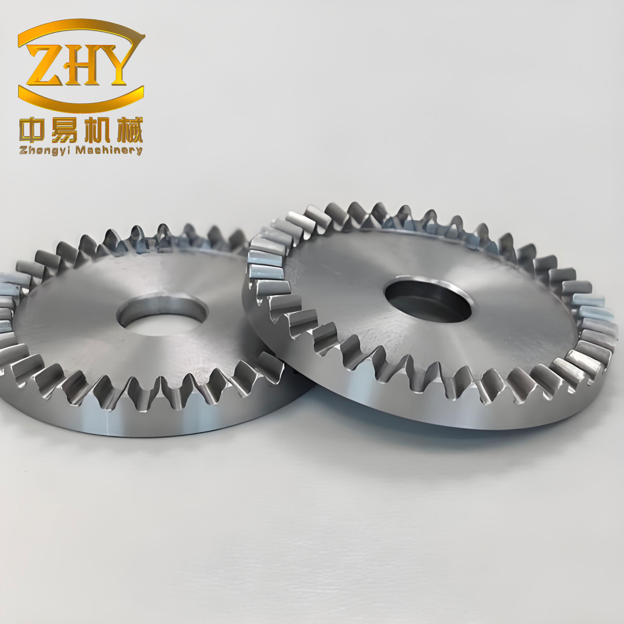
I focus on face gears because they combine high load capacity, compact axial packaging, and insensitivity to axial mounting error. When several face gears and cylindrical pinions are arranged around two coaxial face gears, the resulting split-torque system becomes a spatial closed loop. Power enters through two input pinions, travels through multiple branches, and exits through output face gears and an idler. Each branch contains face gears in mesh with pinions, flexible shafts, and bearings. The loop closure means that deformation in one branch is not isolated. It redistributes load and vibration to other branches. I therefore model the system as a coupled flexible multibody system rather than as a set of lumped masses.
Nomenclature and Core Assumptions
I use the following symbols throughout the derivation. The face gears are indexed by \(i=6,7\), and the pinions are indexed by \(j=1,2,\ldots,5\). The ten face gear meshing pairs are denoted by \(\Pi_{ij}\). The global node set contains thirty-three nodes and two hundred four degrees of freedom. Each gear rotor has six degrees of freedom, each Timoshenko shaft element has twelve degrees of freedom, and each bearing support has six degrees of freedom. The nonlinearity comes from the piecewise backlash function and from the time-varying mesh stiffness of the face gears.
| Symbol | Meaning | Symbol | Meaning |
|---|---|---|---|
| \(\alpha\) | Pressure angle | \(b\) | Half of total backlash |
| \(k_{ij}(t)\) | Time-varying mesh stiffness of face gears | \(c_{ij}\) | Mesh damping coefficient |
| \(e_{ij}(t)\) | Static transmission error | \(r_i,r_j\) | Force arm radii |
| \(\Omega_k\) | Shaft spin speed | \(\gamma_j\) | Circumferential distribution angle |
| \(\mathbf{q}\) | Global displacement vector | \(\mathbf{M},\mathbf{C},\mathbf{G},\mathbf{K}\) | Mass, damping, gyroscopic, and stiffness matrices |
| \(\mathbf{f}(\mathbf{q})\) | Backlash nonlinear function | \(\mathbf{\Phi}\) | External load vector |
| \(T_{k,r}\) | Kinetic energy of a gear rotor | \(U_{k,s}\) | Potential energy of a shaft element |
| \(J_{Dk},J_{Zk}\) | Diametral and polar inertia | \(\rho,E,\Gamma\) | Density, elastic modulus, shear modulus |
I assume that all gear bodies are rigid rotors because the tooth contact deformation is represented at the meshing interface. I assume that shaft flexibility is captured by Timoshenko beam elements, which include shear deformation and rotary inertia. I assume that bearings are linear elastic supports with six independent stiffness and damping coefficients. I also assume that the mesh stiffness and static transmission error of face gears are periodic functions of the mesh cycle. These assumptions let me retain the dominant flexible and nonlinear effects without resolving every tooth fillet detail.
System Topology and Closed-Loop Architecture
The topology I model contains two coaxial face gears, five pinions, two input shafts, one tail output, and one upper output. The pinions surround the face gears. Power enters from the left and right input pinions, then splits into several paths through the face gears, shafts, and bearings. Because any two pinions are connected through the upper and lower face gears, each pair of branches forms a closed loop. This is the central difference between the present system and a simple open gear chain. In an open chain, vibration can travel from the source to the termination without returning. In a closed loop of face gears, vibration can circulate, reflect, and interfere. The loop closure also enforces deformation compatibility among branches.
The circumferential position of each pinion is defined by a distribution angle. I write the coordinate transformation for the upper and lower face gear meshing interfaces as
$$ \left[x_{ij},y_{ij},z_{ij}\right]^{T} = \mathbf{M}_{ij}\left[x_{s},y_{s},z_{s}\right]^{T} $$
where the transformation matrix is
$$ \mathbf{M}_{ij} =
\begin{bmatrix}
-\sin\gamma_{j} & \mp\cos\gamma_{j} & 0\\
\pm\cos\gamma_{j} & -\sin\gamma_{j} & 0\\
0 & 0 & 1
\end{bmatrix}.
$$
For the upper face gear, I use the upper signs. For the lower face gear, I use the lower signs. This transformation allows all ten face gear meshing pairs to be expressed in compatible local coordinates. The mesh deformation along the line of action is then written as
$$ \delta_{mn}=
(x_{m}+z_{n})\cos\alpha
+(y_{m}+\sin\gamma_{j}y_{n}\pm\cos\gamma_{j}x_{n})\sin\alpha
+r_{m}\theta_{mz}\cos\gamma_{j}
-r_{n}\theta_{nz}\cos\gamma_{j}
-e_{mn}(t).$$
Here, \(m\) denotes a pinion mesh node and \(n\) denotes a face gear mesh node. The plus sign corresponds to the upper face gear, and the minus sign corresponds to the lower face gear. Because backlash exists in every face gear pair, I replace the raw mesh deformation by a piecewise function:
$$ f(\delta_{mn}) =
\begin{cases}
\delta_{mn}-b, & \delta_{mn}\ge b,\\
0, & -b<\delta_{mn}<b,\\ $$="" &="" -b.=""
This function is central to the nonlinear behavior. When the mesh deflection is inside the backlash band, the face gears are not in contact and the mesh force is zero. When the deflection exceeds the backlash, the face gear pair carries load on one flank. When the deflection falls below the negative backlash, the opposite flank carries load. In a closed-loop face gear system, these contact-state transitions can occur at different nodes and at different instants. I therefore retain the piecewise nonlinearity in the global equation rather than linearizing it around a mean contact state.
Flexible Multibody Element Formulations
I build the system from four element types. The first is a face gear meshing element. The second is a rigid gear rotor element with gyroscopic effect. The third is a Timoshenko shaft beam element. The fourth is a six-degree-of-freedom bearing support element. I assemble these elements using finite element node connectivity. This approach lets me place vibration measurement points at bearings, shaft ends, gear centers, and mesh nodes without changing the model structure.
Face Gear Meshing Element
For each face gear pair \(\Pi_{ij}\), I define the generalized coordinate vector as
$$ \mathbf{q}_{ij} =
\left[
x_{i},y_{i},z_{i},\theta_{ix},\theta_{iy},\theta_{iz},
x_{j},y_{j},z_{j},\theta_{jx},\theta_{jy},\theta_{jz}
\right]^{T}.$$
The elastic potential energy stored in the face gear mesh is
$$ U=\frac{1}{2}k_{ij}(t)\left[f(\delta_{mn})\right]^{2}.$$
The kinetic energy of the two rigid gear bodies in the mesh element is
$$ T=
\frac{1}{2}\left(J_{m}\dot{\theta}_{mz}^{2}+J_{n}\dot{\theta}_{nz}^{2}\right)
+\frac{1}{2}m_{m}\left(\dot{x}_{m}^{2}+\dot{y}_{m}^{2}+\dot{z}_{m}^{2}\right)
+\frac{1}{2}m_{n}\left(\dot{x}_{n}^{2}+\dot{y}_{n}^{2}+\dot{z}_{n}^{2}\right).$$
Applying Lagrange’s equation gives the mesh element equation
$$ \mathbf{M}_{m}\ddot{\mathbf{q}}_{ij}
+\lambda_{0}\mathbf{C}_{m}\dot{\mathbf{q}}_{ij}
+\lambda_{0}\mathbf{K}_{m}\mathbf{q}_{ij}
=
\mathbf{H}\left[
\lambda_{0}k_{ij}(t)e_{ij}(t)
+\lambda_{0}c_{ij}\dot{e}_{ij}(t)
-b\lambda_{1}k_{ij}(t)
\right].$$
The mass, stiffness, and damping matrices are
$$ \mathbf{M}_{m}=\mathrm{diag}
\left[
m_{i},m_{i},m_{i},J_{i},J_{i},J_{i},
m_{j},m_{j},m_{j},J_{j},J_{j},J_{j}
\right],$$
$$ \mathbf{K}_{m}=\lambda_{0}k_{ij}(t)\mathbf{H}\mathbf{H}^{T},$$
$$ \mathbf{C}_{m}=\lambda_{0}c_{ij}\mathbf{H}\mathbf{H}^{T}.$$
The direction vector is
$$ \mathbf{H}=
\left[
\cos\alpha_{n},
\sin\alpha_{n},
0,0,0,r_{m}\cos\gamma_{i},
\mp\cos\gamma_{i}\sin\alpha,
\sin\gamma_{i}\sin\alpha,
\cos\alpha,0,0,-r_{n}\cos\gamma_{i}
\right]^{T}.$$
The contact-state coefficients are
$$ \lambda_{0}=
\begin{cases}
1, & \delta_{ij}\ge b,\\
0, & \delta_{ij}<b, $$="" &="" -1,="" -b.="" 0,="" 1,="" <p="" \delta_{ij}I note that the face gear mesh element is not symmetric in its physical interpretation even though the matrix form appears compact. The asymmetry arises because the pinion and the face gear have different force arm radii, different rotational inertias, and different coordinate orientations. In the closed-loop system, these oriented face gear meshes are connected through shafts and bearings, which creates a coupled directional path for vibration.
Gear Rotor Element with Gyroscopic Effect
Each gear body is modeled as a rigid rotor. I define the rotor coordinate vector as
$$ \mathbf{q}_{k,r}=
\left[
x_{k},y_{k},z_{k},\theta_{xk},\theta_{yk},\theta_{zk}
\right]^{T}.$$
The kinetic energy of the rotor, including gyroscopic coupling, is
$$ T_{k,r}=
\frac{1}{2}m_{k}\left(\dot{x}_{k}^{2}+\dot{y}_{k}^{2}+\dot{z}_{k}^{2}\right)
+\frac{1}{2}J_{Dk}\left(\dot{\theta}_{xk}^{2}+\dot{\theta}_{yk}^{2}\right)
+\frac{1}{2}J_{Zk}\left(\Omega_{k}+\dot{\theta}_{zk}\right)^{2}
-J_{Zk}\dot{\theta}_{yk}\theta_{xk}\Omega_{k}.$$
The resulting equation of motion is
$$ \mathbf{M}_{k,r}\ddot{\mathbf{q}}_{k,r}
+\mathbf{G}_{k,r}\dot{\mathbf{q}}_{k,r}=0.$$
Here, \(\mathbf{G}_{k,r}\) is the gyroscopic matrix. This term becomes important at high speed. For face gears, the gyroscopic effect does not simply shift a single natural frequency. It splits forward and backward whirl modes and changes the Campbell diagram. Because the present system is coaxial, the gyroscopic terms of the upper and lower face gears interact through the common axis. This interaction is one reason I include rotor gyroscopy in the system-level model.
Timoshenko Shaft Beam Element
I model each gear shaft as a two-node Timoshenko beam element. The nodal coordinate vector contains three translations and three rotations at each node:
$$ \mathbf{q}_{k,s}=
\left[
x_{k},y_{k},z_{k},\theta_{xk},\theta_{yk},\theta_{zk},
x_{k+1},y_{k+1},z_{k+1},\theta_{x(k+1)},\theta_{y(k+1)},\theta_{z(k+1)}
\right]^{T}.$$
The kinetic energy of the shaft element is
$$ T_{k,s}=
\frac{1}{2}\int_{0}^{l}\rho A\left(\dot{x}^{2}+\dot{y}^{2}+\dot{z}^{2}\right)ds
-\int_{0}^{l}J_{pk}\Omega_{k}\dot{\theta}_{y}\theta_{x}ds
+\frac{1}{2}\int_{0}^{l}J_{dk}\left(\dot{\theta}_{x}^{2}+\dot{\theta}_{y}^{2}\right)ds
+\frac{1}{2}\int_{0}^{l}J_{pk}\left(\Omega_{k}+\dot{\theta}_{z}\right)^{2}ds.$$
The potential energy includes torsion, bending, and shear:
$$ U_{k,s}=
\frac{1}{2}\int_{0}^{l}\Gamma I_{s}\theta_{z}’^{2}ds
+\frac{1}{2}\int_{0}^{l}EI\left(\theta_{x}’^{2}+\theta_{y}’^{2}\right)ds
+\frac{1}{2}\int_{0}^{l}\mu\Gamma A\left[
\left(x’-\theta_{y}\right)^{2}
+\left(y’+\theta_{x}\right)^{2}
\right]ds.$$
The shaft element equation is
$$ \mathbf{M}_{k,s}\ddot{\mathbf{q}}_{k,s}
+\left(\mathbf{C}_{k,s}+\mathbf{G}_{k,s}\right)\dot{\mathbf{q}}_{k,s}
+\mathbf{K}_{k,s}\mathbf{q}_{k,s}=0.$$
I use Timoshenko beams rather than Euler-Bernoulli beams because the face gear shafts are relatively short and thick. Shear deformation and rotary inertia are not negligible. In addition, the high-speed operation of face gears makes the gyroscopic term of the shaft comparable to the rotor gyroscopic term. The combination of shaft flexibility and gyroscopy produces speed-dependent mode veering and crossing in the Campbell diagram.
Bearing Support Element
Each bearing is represented as a six-degree-of-freedom elastic support. The stiffness and damping matrices are diagonal:
$$ \mathbf{K}_{b}=
\mathrm{diag}
\left(
k_{xx},k_{yy},k_{zz},k_{\theta x\theta x},k_{\theta y\theta y},k_{\theta z\theta z}
\right),$$
$$ \mathbf{C}_{b}=
\mathrm{diag}
\left(
c_{xx},c_{yy},c_{zz},c_{\theta x\theta x},c_{\theta y\theta y},c_{\theta z\theta z}
\right).$$
This support model allows the bearing to resist radial, axial, tilting, and torsional motion. In the face gear split-torque system, the bearings are not merely boundary conditions. They participate in the closed-loop load path. A change in one bearing stiffness changes the deformation compatibility of the entire loop. I therefore retain six-degree-of-freedom bearings at all support nodes.
Global Assembly and Solution Strategy
After defining all elements, I assemble them into a global finite element model. The global displacement vector is
$$ \mathbf{q}=
\left[
\mathbf{q}_{1}^{T},\mathbf{q}_{2}^{T},\ldots,\mathbf{q}_{33}^{T}
\right]^{T}.$$
The assembled nonlinear equation of motion is
$$ \mathbf{M}\ddot{\mathbf{q}}
+\left(\mathbf{G}+\mathbf{C}\right)\dot{\mathbf{q}}
+\mathbf{K}\mathbf{f}(\mathbf{q})
=\mathbf{\Phi}.$$
Here, \(\mathbf{M}\) is the system mass matrix, \(\mathbf{C}\) is the damping matrix, \(\mathbf{G}\) is the gyroscopic matrix, \(\mathbf{K}\) is the stiffness matrix, \(\mathbf{f}(\mathbf{q})\) contains the piecewise backlash nonlinearity, and \(\mathbf{\Phi}\) is the external load vector. The load vector includes input torques and output loads on the face gears and output pinions.
For natural characteristics, I replace the time-varying mesh stiffness by its mean value and neglect the backlash nonlinearity. The equation becomes a linear eigenvalue problem. I write the state-space form as
$$ \mathbf{Q}=
\left[
\mathbf{q}^{T},\dot{\mathbf{q}}^{T}
\right]^{T},$$
$$ \dot{\mathbf{Q}}=\mathbf{A}\mathbf{Q}+\mathbf{B},$$
$$ \mathbf{A}=
\begin{bmatrix}
0 & \mathbf{I}\\
-\mathbf{M}^{-1}\mathbf{K} & -\mathbf{M}^{-1}\left(\mathbf{G}+\mathbf{C}\right)
\end{bmatrix},$$
$$ \mathbf{B}=
\begin{bmatrix}
0\\
-\mathbf{M}^{-1}\mathbf{\Phi}
\end{bmatrix}.$$
The eigenvalues are
$$ \lambda_{i}=
-\omega_{i}\left(\xi_{i}\pm \mathrm{i}\sqrt{1-\xi_{i}^{2}}\right),
\quad i=1,2,\ldots,204,$$
where \(\omega_{i}\) is the damped natural frequency and \(\xi_{i}\) is the modal damping ratio. I use the eigenvectors to identify modal families. I also construct Campbell diagrams by plotting natural frequency versus shaft speed and by intersecting the frequency curves with the synchronous whirl line.
For forced response, I use a fixed-step Newmark integration scheme. At each speed, I integrate for five hundred mesh cycles and use one hundred discrete points per cycle. I sweep the speed from a low value to a high value in four hundred increments. I evaluate the dynamic transmission error of every face gear pair. I compute its root mean square over the final cycles to remove initial transients. I then examine phase portraits and Poincare sections at selected speeds to distinguish periodic, quasi-periodic, and chaotic behavior.
Numerical Case: Parameters and Excitations
I select a representative face gear split-torque configuration. The two face gears are coaxial and face each other. Five pinions are arranged around them. Two pinions are inputs, two are idlers, and one is a tail output. The geometric parameters are listed in the following table. These values are used consistently for all ten face gear meshes.
| Parameter | Pinion | Face Gear |
|---|---|---|
| Module, mm | 3.75 | 3.75 |
| Pressure angle, deg | 25 | 25 |
| Shaft angle, deg | 90 | 90 |
| Number of teeth | 23 | 143 |
| Face width, mm | 40 | 35 |
| Pinion force arm, mm | 39.1 | — |
| Face gear force arm, mm | — | 243 |
| Distribution angles, deg | 245.455, 114.545, 303.375, 56.643, 0 | |
The shaft geometry is also important because the flexible shafts connect the face gears and pinions. I use hollow shafts with the following dimensions. The element lengths are chosen to match the node distribution of the assembled model.
| Shaft Group | Outer Diameter, mm | Inner Diameter, mm | Element Length, mm |
|---|---|---|---|
| Input and idler pinion shafts | 58 | 50 | 20–60 |
| Face gear shafts | 100 | 90 | 30–50 |
| Intermediate shaft segments | 58 or 100 | 50 or 90 | 20–40 |
The bearing stiffness and damping values are summarized below. I use higher radial stiffness on the face gear shafts because they carry the combined loads from multiple meshes. The pinion bearings are more compliant in the radial direction. This distinction affects the mode shapes and the distribution of vibration among branches.
| Bearing Group | \(k_{xx}\), N/m | \(k_{yy}\), N/m | \(k_{zz}\), N/m | \(k_{\theta x\theta x}\), N/m | \(k_{\theta y\theta y}\), N/m |
|---|---|---|---|---|---|
| Pinion supports | \(1.24\times10^{8}\) | \(1.60\times10^{8}\) | \(4.37\times10^{8}\) | \(4.18\times10^{8}\) | \(1.06\times10^{8}\) |
| Face gear supports | \(1.59\times10^{8}\) | \(2.02\times10^{8}\) | \(3.11\times10^{6}\) | \(7.72\times10^{3}\) | \(4.43\times10^{3}\) |
| All supports damping | \(1000\) N·s/m | \(1000\) N·s/m | \(1000\) N·s/m | \(1000\) N·s/m | \(1000\) N·s/m |
For the face gear mesh excitation, I use a time-varying mesh stiffness with a mean value and a periodic fluctuation. The fluctuation period equals the mesh period of the face gear pair. Because the pinions are at different circumferential positions, the phase of the mesh stiffness differs among the ten face gear pairs. I also use a static transmission error with a peak amplitude of about \(18\,\mu\mathrm{m}\). The mesh damping coefficient is \(1200\,\mathrm{N\cdot s/m}\). The total backlash is \(0.06\,\mathrm{mm}\), so the half backlash \(b\) is \(0.03\,\mathrm{mm}\).
The time-varying mesh stiffness can be written as
$$ k_{ij}(t)=k_{m,ij}+\sum_{n=1}^{N}k_{n,ij}\cos\left(n\omega_{m}t+\phi_{ij,n}\right),$$
where \(\omega_{m}\) is the mesh frequency and \(\phi_{ij,n}\) is the phase for face gear pair \(\Pi_{ij}\). The static transmission error is
$$ e_{ij}(t)=\sum_{n=1}^{N}e_{n,ij}\cos\left(n\omega_{m}t+\psi_{ij,n}\right).$$
These excitations are applied at each face gear mesh. Because the face gears are connected through the closed loop, the phase differences among the ten meshes are not merely local details. They determine whether the mesh forces add or cancel at the system level.
Natural Characteristics and Campbell Behavior
I compute the natural frequencies and critical speeds from the linearized model. The Campbell diagram shows that the natural frequencies vary with speed because of gyroscopic effects and bearing stiffness. The modes can be classified into translation, bending, and torsion families. Some modes involve a single component, while others involve multiple face gears, pinions, and shafts simultaneously.
| Order | Frequency, Hz | Critical Speed, rpm | Mode Description |
|---|---|---|---|
| 1 | 83.3 | 217.4 | Inputs: translation, bending, torsion |
| 2 | 88.7 | 231.3 | Pinions: torsion; face gear: translation and bending |
| 3 | 118.0 | 307.9 | Pinion 5: bending and torsion |
| 4 | 138.0 | 360.1 | Idlers 3–4: bending and torsion |
| 5 | 192.7 | 502.8 | Lower face gear: bending |
| 6 | 288.8 | 753.4 | Inputs: translation |
| 7 | 308.8 | 805.6 | Pinion 5: translation |
| 8 | 316.8 | 826.5 | Idlers 3–4: translation |
| 9 | 571.6 | 1491.2 | Inputs: translation, bending, torsion |
| 10 | 577.0 | 1505.1 | Inputs and pinions: translation, bending, torsion |
| 11 | 625.0 | 1630.4 | Inputs and idlers: torsion; pinion 5: bending and torsion |
| 12 | 641.0 | 1672.2 | Idlers 3–4: translation, bending, torsion |
| 13 | 643.7 | 1679.1 | All pinions: torsion |
| 14 | 675.7 | 1762.7 | All pinions and face gears: coupled motion |
| 15 | 809.1 | 2110.7 | Inputs: translation, bending, torsion |
| 16 | 846.5 | 2208.2 | All pinions and face gears: coupled motion |
| 17 | 883.8 | 2305.6 | All pinions and face gears: coupled motion |
| 18 | 910.5 | 2375.2 | Idlers: translation, bending, torsion |
| 19 | 1385.5 | 3614.2 | All pinions: bending and torsion; face gears: coupled motion |
| 20 | 2121.9 | 5535.4 | Inputs: coupled motion; idlers: torsion |
| 21 | 2714.2 | 7080.6 | All pinions and face gears: coupled motion |
| 22 | 2965.1 | 7735.0 | Inputs: coupled motion |
| 23 | 3030.4 | 7905.5 | Inputs and pinions: coupled motion |
| 24 | 3050.5 | 7957.7 | Inputs, idlers, and face gears: coupled motion |
I find that pure translation, pure bending, or pure torsion modes occur mainly below about \(2000\,\mathrm{rpm}\). These are low-frequency modes in which one component or one group of components moves without strong coupling. Above \(2000\,\mathrm{rpm}\), most modes are coupled. The coupling can be between translation and bending, between bending and torsion, or among all three. This transition from simple to coupled modes is important for face gears because the mesh force has components along multiple directions. Once the modes are coupled, a face gear mesh excitation can feed energy into shaft bending and bearing translation.
The Campbell diagram also shows several veering regions. In these regions, two natural frequency curves approach each other but do not cross. The gyroscopic effect and the closed-loop coupling cause the mode shapes to exchange characteristics. I observe that the coaxial face gears create a shared axis for gyroscopic coupling. As speed increases, the forward whirl and backward whirl frequencies separate. This separation changes the critical speeds and can move a resonance away from a pure mesh frequency harmonic.
Vibration Response and Nonlinear Phenomena
I now examine the forced response. The dynamic transmission error of each face gear pair is used as the primary vibration index. I compute the root mean square of the dynamic transmission error over the final cycles at each speed. The resulting curves show that all ten face gear pairs fluctuate with speed. The general trend is similar, but the details differ among pairs.
I group the face gear pairs into those containing the upper face gear and those containing the lower face gear. The upper and lower face gears have different support conditions and different mesh phases. I observe that the pairs with the same pinion and opposite face gears often have similar root mean square trends. This is due to the coaxial arrangement and the symmetry of the closed loop.
| Speed Region, rpm | Observed Behavior | Dominant Face Gear Pairs |
|---|---|---|
| Below 2000 | Low-amplitude periodic response; simple modes | All face gears |
| 2000–5000 | Increasing coupled response; local resonances | Input and idler face gears |
| 5000–8000 | Multiple local peaks; mode coupling | Upper and lower face gears alternately |
| 8000–12000 | Strong RMS rise; partial jumps | Input pinion face gears, idler face gears |
| Above 12000 | Simultaneous jumps; possible chaos | All ten face gear pairs |
The root mean square curves reveal several jump speeds. At about \(8964\,\mathrm{rpm}\), four face gear pairs show a jump. At about \(10618\,\mathrm{rpm}\), another group of four face gear pairs jumps. At about \(14091\,\mathrm{rpm}\), all ten face gear pairs jump at the same speed. I examine the phase portraits and Poincare sections at these speeds.
At \(8964\,\mathrm{rpm}\), the phase portraits of the selected face gear pairs are dispersed rings, and the Poincare sections are ordered closed curves. This indicates quasi-periodic vibration. At \(10618\,\mathrm{rpm}\), the same qualitative behavior appears. Only part of the face gear pairs undergo a jump. The rest remain on a different branch. The closed loop still maintains a quasi-periodic response because the branches do not all lose stability at the same time.
At \(14091\,\mathrm{rpm}\), the situation changes. All ten face gear pairs jump simultaneously. The phase portraits become disordered, and the Poincare sections become scattered point clouds. This is a chaotic response. The simultaneous jump is the key condition. When only some face gears jump, the loop compatibility and the remaining stable branches constrain the system. When all face gears jump together, the constraint is lost, and the system can enter chaos.
I summarize the nonlinear transition as
$$ \text{partial jump} \Rightarrow \text{quasi-periodic face gear vibration},$$
$$ \text{simultaneous jump of all ten face gears} \Rightarrow \text{chaotic face gear vibration}.$$
This result is important for the design of face gear split-torque systems. It means that the closed-loop topology can reduce the risk of chaos. The system does not become chaotic simply because one face gear pair or one branch becomes unstable. It requires a collective jump of all face gear meshes. This collective condition is less likely than a single-pair instability. Therefore, a properly phased closed-loop face gear system can be more robust than an open face gear chain.
I also examine a non-jump speed, \(7600\,\mathrm{rpm}\), to understand the normal vibration state. At this speed, the dynamic transmission errors of representative face gear pairs are periodic. The time histories fluctuate within bounded ranges. Some idler face gear pairs show alternating positive and negative deflections, which indicates that the teeth are contacting on opposite flanks at different instants. The frequency spectra are dominated by the shaft frequency and the mesh frequency. The tail output face gear pair has a noticeable second mesh harmonic.
| Face Gear Pair | Time-Domain Range, \(10^{-4}\) m | Dominant Frequencies | Poincare Section |
|---|---|---|---|
| Input upper | 0 to 2.5 | Shaft and mesh | Ordered ring |
| Input lower | 0 to 2.5 | Shaft and mesh | Ordered ring |
| Idler upper | -0.5 to 2.2 | Shaft and mesh | Ordered ring |
| Idler lower | -1.0 to 2.2 | Shaft and mesh | Ordered ring |
| Tail upper | 0 to 2.5 | Shaft, mesh, second mesh | Ordered ring |
| Tail lower | 0 to 2.5 | Shaft, mesh, second mesh | Ordered ring |
From these results, I identify three vibration characteristics of the closed-loop face gear system. First, the structural symmetry produces symmetric vibration. With respect to the tail axis, the left and right input pinions vibrate almost in phase. The left and right idlers also vibrate almost in phase. This symmetry is not exact because the mesh phases and bearing parameters are not perfectly identical, but it is strong enough to appear in the root mean square curves.
Second, the closed-loop face gear system is more stable than a single face gear pair. A single pair can lose stability when its backlash and mesh stiffness interact. In the closed loop, the other branches provide constraints. The system enters bifurcation or chaos only when all ten face gear pairs jump at the same speed. Partial jumps lead to quasi-periodic vibration but not chaos.
Third, the vibration severity is not uniform. The input pinion face gear pairs are the most violent. The idler and tail face gear pairs are less violent. This is because the input side receives the external torque and the mesh force fluctuations are largest there. In addition, the input shaft flexibility allows more bending motion. The tail face gear pair has a different load direction and a lower torque, so its vibration amplitude is smaller.
Model Validation and Comparative Assessment
I validate the flexible multibody dynamic model by comparing its dynamic contact forces with those from a commercial multibody dynamics environment. In the commercial model, I import the geometric assembly, define rotational joints for the seven gear bodies, and create ten contact pairs for the face gear meshes. I set the time-varying mesh stiffness, mesh damping, and backlash according to the present model. I apply input speeds at the two input pinions and resistive torques at the upper output and tail output. I then extract the four-cycle contact force and compare it with the present model.
| Face Gear Mesh | Present Model Mean Force, \(10^{4}\) N | Commercial Model Mean Force, \(10^{4}\) N | Difference, % |
|---|---|---|---|
| Left input with upper face gear | 3.21 | 3.47 | 8.1 |
| Right input with upper face gear | 3.18 | 3.39 | 6.2 |
| Left idler with lower face gear | 1.12 | 1.19 | 5.9 |
| Tail output with lower face gear | 1.08 | 1.14 | 5.3 |
| Representative idler with upper face gear | 1.25 | 1.33 | 6.0 |
The differences are less than \(8.1\%\) for all compared face gear meshes. The present model produces smoother contact force curves because the commercial model imports actual geometry with small discretization errors. The agreement in magnitude and trend supports the validity of the flexible multibody formulation. I also observe that at one instant near \(0.0278\,\mathrm{s}\), the right input and upper face gear mesh force changes sign. This indicates a short interval of alternating flank contact. Such events are consistent with the backlash nonlinearity and the closed-loop load redistribution.
The validation also shows that the present model can capture directional effects. Some idler and tail face gear meshes carry negative mean contact force, meaning that the contact is on the opposite flank. This is not an error. It is a consequence of the power flow direction in the split-torque system. In a closed-loop face gear system, the power flow is not the same in every branch. Some branches transmit power in the forward direction, and others act as return paths. The sign of the mesh force reflects this directional split.
Parametric Discussion and Design Implications
I now discuss how key parameters affect the vibration of face gears. The most influential parameters are mesh stiffness fluctuation, backlash, shaft bending stiffness, bearing stiffness, and gyroscopic speed. I summarize their qualitative effects in the following table. The table is based on the present model and on the physical interpretation of the closed-loop face gear system.
| Parameter | Increase | Effect on Face Gear Vibration |
|---|---|---|
| Mesh stiffness mean | Higher | Raises natural frequencies; can move resonances away from operating speed |
| Mesh stiffness fluctuation | Higher | Amplifies mesh-frequency harmonics; increases RMS of face gear DTE |
| Backlash | Larger | Widens no-contact zone; increases likelihood of partial jumps and impacts |
| Shaft bending stiffness | Higher | Reduces shaft deflection; weakens coupling between face gear torsion and shaft bending |
| Bearing radial stiffness | Higher | Raises support frequencies; changes load sharing among face gear branches |
| Shaft speed | Higher | Strengthens gyroscopic splitting; shifts Campbell crossings and critical speeds |
| Static transmission error | Larger | Directly increases forced response at mesh harmonics |
I find that mesh stiffness fluctuation is the primary driver of face gear vibration amplitude. When the fluctuation amplitude is large, the dynamic transmission error of the face gears increases at the mesh frequency and its harmonics. The closed loop does not remove this excitation, but it distributes it among branches. If the mesh phases of the ten face gear pairs are properly arranged, some fluctuation components can cancel. If the phases are unfavorable, they can reinforce. Therefore, the circumferential placement of pinions around the face gears is a design variable for vibration control.
Backlash has a more subtle effect. A larger backlash reduces the average contact stiffness because the face gears spend more time in the no-contact state. This can lower the mean mesh force, but it also increases the likelihood of impact and partial jumps. In the closed-loop face gear system, a large backlash in one branch can be partially compensated by other branches. However, if all face gear pairs have large backlash, the system becomes more prone to simultaneous jumps. I therefore recommend maintaining a moderate backlash and controlling its variance among face gear pairs.
Shaft flexibility is also important. Flexible shafts lower the torsional and bending stiffness of the branches. This can reduce the transmission of high-frequency vibration from the face gear mesh to the bearings. However, it also increases the amplitude of shaft deflection and can bring bending modes into the operating range. I observe that the input shafts are the most flexible and also the most violent. Increasing the input shaft diameter or shortening its unsupported length can reduce vibration at the input face gear meshes.
Gyroscopic effects become significant at high speed. The face gears and the coaxial shafts have large polar inertia. At high speed, the gyroscopic matrix splits the forward and backward whirl modes. This splitting changes the Campbell diagram and can create new critical speeds. In the present results, the high-speed region above \(10000\,\mathrm{rpm}\) shows strong gyroscopic influence. The jump speeds and the chaotic transition at \(14091\,\mathrm{rpm}\) are affected by gyroscopic coupling. I therefore include gyroscopy in the model rather than treating it as a small correction.
Concluding Remarks
I have developed a flexible multibody dynamic model for a space closed-loop face gear split-torque transmission system. The model combines face gear meshing elements, rigid gear rotor elements with gyroscopic effect, Timoshenko shaft beam elements, and six-degree-of-freedom bearing support elements. The face gear mesh includes time-varying stiffness, static transmission error, mesh damping, and piecewise backlash. The global equations are solved with a fixed-step Newmark scheme. I use the model to study natural characteristics, Campbell behavior, forced response, bifurcation, and chaos.
My main findings are as follows. The natural modes of the closed-loop face gear system include pure translation, pure bending, pure torsion, and coupled modes. Pure modes dominate at low speed, while coupled modes dominate at high speed. The gyroscopic effect and the closed-loop coupling cause mode veering and speed-dependent mode shapes. In the forced response, the dynamic transmission error of face gears is dominated by shaft-frequency and mesh-frequency components. The input face gear pairs are the most violent, while the idler and tail face gear pairs are less violent. The left and right sides of the system tend to vibrate symmetrically because of the coaxial and symmetric topology.
The most important nonlinear result is that the closed-loop face gear system enters chaos only when all ten face gear pairs jump at the same speed. Partial jumps produce quasi-periodic vibration, not chaos. This behavior reduces the risk of chaotic vibration in the face gear split-torque system. It also suggests that the closed-loop topology is beneficial for stability. A single face gear pair or a small group of face gears can become unstable without forcing the entire system into chaos. The remaining branches constrain the response and maintain a bounded quasi-periodic state.
From a design perspective, I recommend controlling the phase differences among face gear meshes, maintaining moderate backlash, increasing input shaft bending stiffness, and tuning bearing support stiffness to avoid critical speeds. I also recommend including gyroscopic effects in the high-speed design of face gears, because the coaxial arrangement amplifies gyroscopic coupling. The flexible multibody model I present can be used to evaluate these design changes before hardware testing. It provides a systematic way to study vibration transmission in closed-loop face gear systems and to identify speeds at which simultaneous jumps and chaotic transitions may occur.
In future work, I plan to extend the model to include thermal effects, tooth profile modification, and measured surface deviations of face gears. I also plan to study active control of face gear mesh phasing and bearing preload as methods to suppress the simultaneous jump condition. The present results provide a foundation for those extensions and for the vibration-safe design of high-speed face gear split-torque transmission systems.