
I began this study from a practical problem in gear cutting. In gear cutting, the tooth line of a helical gear is not a simple straight feature. It is a parameterized spiral that wraps around a cylinder, and its geometric behavior changes with module, number of teeth, face width, rotation angle, and the local spiral angle. When I examined conventional inspection methods, I found that they often treat the pitch circle spiral angle and the tip circle spiral angle as if their relationship were fixed or weakly coupled. In actual gear cutting, this assumption is not sufficient. The small changes in the spiral line and the dynamic coupling among parameters cause large uncertainty in spiral angle deviation measurement. Therefore, I developed a laser interference detection algorithm that first derives the tangent relationship between the pitch circle spiral angle and the tip circle spiral angle, then uses laser interferometry to measure the relevant gear parameters, and finally computes the actual spiral angle and its deviation from the standard value.
The central idea of my method is that accurate detection of spiral angle deviation in gear cutting must be based on the true parameterized spiral equation, not on a simplified projection or a purely contact-based probe reading. I therefore derive the spiral line in a spatial Cartesian coordinate system, analyze its projection behavior, and obtain the tangent values for the pitch circle and the tip circle. These tangent values provide the mathematical bridge between the ideal gear geometry and the measured interference signal. After that, I use a laser interferometer to measure module, tooth number, rotation angle, and face width. The actual spiral angle is then calculated and compared with the standard spiral angle to obtain the deviation.
I organize the article as follows. First, I explain the limitations of traditional spiral angle analysis in gear cutting. Second, I derive the spiral line parameter equations and the tangent relationship. Third, I present the laser interference measurement model, including frequency shift, phase equation, and optical feedback. Fourth, I describe how I extract the gear cutting parameters and compute the actual spiral angle. Fifth, I report comparative experiments against a roll-grinding calculation method and a parameter vision detection method. Finally, I summarize the advantages of the proposed algorithm for gear cutting accuracy and helical gear quality control.
1. Limitations of Traditional Spiral Angle Analysis in Gear Cutting
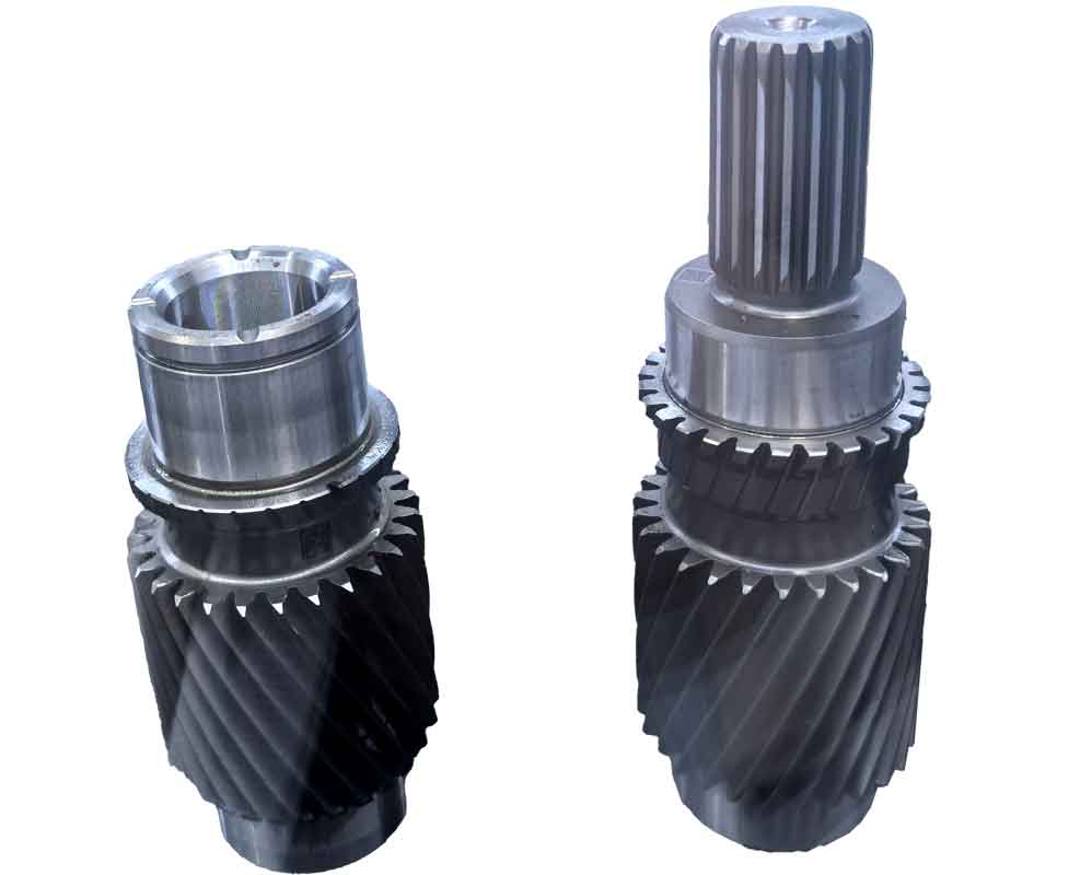
In gear cutting, helical gears are widely used because they transmit motion more smoothly and with lower noise than spur gears. However, the spiral angle directly affects axial force, contact ratio, load distribution, and transmission error. If the spiral angle deviates from its standard value, the gear pair may vibrate, generate noise, and wear unevenly. For this reason, spiral angle deviation detection is an important part of gear cutting quality inspection.
Traditional methods can be grouped into geometric projection methods, contact probe methods, process calculation methods, dynamic model methods, and vision-based methods. Each has useful features, but each also has a limitation that becomes serious when the goal is precise spiral angle deviation detection in gear cutting.
| Traditional Method | Basic Principle | Main Limitation in Gear Cutting |
|---|---|---|
| Geometric projection | Projects the spiral line onto a plane and estimates the angle from the projected shape. | It cannot capture small changes of the spiral line at different positions along the tooth width. |
| Contact probe | Uses a probe to touch the tooth surface and record coordinates. | It gives direct data but does not fully consider dynamic coupling among module, tooth number, rotation angle, and face width. |
| Roll-grinding calculation | Uses process parameters and simplified transmission relations to estimate geometric error. | It follows simplified error relations and does not optimize the exact tangent relation between pitch circle and tip circle spiral angles. |
| Dynamic model | Analyzes axial, transverse, and torsional vibration of the helical gear pair. | Vibration may correlate with deviation, but it cannot replace direct calculation of the tangent relation of the spiral angle. |
| Parameter vision | Collects gear images and fits the tip circle and root circle by least squares. | Independent fitting of tip and root features does not accurately reflect the true tangent relation between pitch circle and tip circle spiral angles. |
These limitations explain why I focus on a laser interference approach. In gear cutting, the spiral angle is not an isolated scalar. It is coupled with the spiral line geometry, the rotation of the gear blank, the tool path, and the measurement coordinate system. A method that ignores this coupling will produce a deviation value that is mathematically convenient but physically incomplete. My algorithm addresses this by deriving the tangent values from the spiral equation and then measuring the actual gear cutting parameters with high precision.
2. Spiral Line Geometry and Parameter Equation
I place the helical gear spiral line in a spatial Cartesian coordinate system. Let the gear radius be \(r\), the number of teeth be \(c\), the face width or axial thickness parameter be \(b\), and the angle parameter be \(\theta\). The spiral line can be written as a set of parametric equations. In my derivation, I use the following form:
$$x = r \cos\left(\theta + \frac{2(n-1)\pi}{c} + \theta_0\right)$$
$$y = r \sin\left(\theta + \frac{2(n-1)\pi}{c} + \theta_0\right)$$
$$z = \pm b\theta = \pm r\theta \cot\beta = \pm \frac{r\theta}{\tan\beta}$$
Here, \(n\) is the spiral line index, \(\theta_0\) is the initial angle, and \(\beta\) is the spiral angle of the pitch circle. The sign of \(z\) determines the direction of rotation. When the gear parameters cause the spiral to rotate to the left, the sign is negative; when the spiral rotates to the right, the sign is positive. This equation is more informative than a simple projected line because it preserves the three-dimensional coupling between radial position, angular position, and axial position.
From the above equations, I can express the radial coordinate as a function of the axial coordinate. Since \(z = r\theta/\tan\beta\), I obtain \(\theta = z\tan\beta/r\). Substituting this into the expression for \(x\) gives:
$$x = r \cos\left(\frac{z\tan\beta}{r} + \frac{2\pi n}{c} + \theta_0\right)$$
Similarly, the axial coordinate can be expressed as a function of the radial coordinate:
$$z = \frac{r}{\tan\beta}\left(\arccos\left(\frac{x}{r}\right) – \frac{2\pi n}{c} – \theta_0\right)$$
These relations show that the spiral line is not exactly straight in any projection plane. Its projection is only approximately straight over a short interval. In gear cutting, the local slope of this projection is connected to the local spiral angle. Therefore, a method that assumes a perfectly straight projection will lose accuracy. My derivation keeps the nonlinear terms and the parameter interactions, which is essential for precise spiral angle deviation detection.
3. Tangent Relationship Between Pitch Circle and Tip Circle Spiral Angles
For a standard external helical gear, the pitch circle diameter is related to the module and the number of teeth. Let \(m\) be the module and \(c\) be the number of teeth. The pitch circle diameter \(d\) is:
$$d = mc$$
The tip circle diameter \(d_y\) is larger than the pitch circle diameter by twice the addendum. For a standard gear, the addendum is equal to the module, so:
$$d_y = d + 2m = m(c+2)$$
The spiral angle on the pitch circle is \(\beta\), and the spiral angle on the tip circle is \(\beta_y\). Using the lead \(P_Z\) of the spiral surface, the tangent values are:
$$\tan\beta = \frac{\pi P_Z}{d}$$
$$\tan\beta_y = \frac{\pi P_Z}{d_y}$$
By combining the two expressions, I eliminate the lead and obtain a direct relation between the two tangent values:
$$\tan\beta_y = \frac{d}{d_y}\tan\beta = \frac{c}{c+2}\tan\beta$$
This equation is the core of my geometric derivation. It shows that the tangent value at the tip circle is not independent of the tangent value at the pitch circle. Instead, it is scaled by the ratio of the pitch circle diameter to the tip circle diameter. In gear cutting, this ratio changes with the number of teeth and the module. If a method ignores this scaling, the calculated deviation will contain a systematic error. My laser interference algorithm uses this tangent relation as a constraint when converting measured displacement into an actual spiral angle.
| Symbol | Meaning | Role in Gear Cutting Spiral Angle Detection |
|---|---|---|
| \(m\) | Module | Determines pitch circle diameter and tooth size in gear cutting. |
| \(c\) | Number of teeth | Controls the ratio between pitch circle and tip circle tangent values. |
| \(d\) | Pitch circle diameter | Reference diameter for the standard spiral angle. |
| \(d_y\) | Tip circle diameter | Used to derive the tip circle spiral angle from the pitch circle spiral angle. |
| \(\beta\) | Pitch circle spiral angle | Nominal spiral angle of the gear cutting process. |
| \(\beta_y\) | Tip circle spiral angle | Local spiral angle at the outer diameter. |
| \(P_Z\) | Spiral surface lead | Connects the tangent values on different circles. |
The tangent relation can also be written in terms of the actual pitch circle and tip circle measurements. If I measure the pitch circle diameter and the tip circle diameter independently, I can compute the expected tip circle tangent value from the measured pitch circle tangent value. Any difference between the expected and measured tip circle tangent value indicates a deviation in the gear cutting process or in the measurement setup. This is one way my algorithm improves robustness.
4. Laser Interference Measurement Model
After deriving the tangent values, I need actual measurements of the gear cutting parameters. I use a laser interferometer because it provides high resolution and is sensitive to small displacements. The laser interferometer emits two polarized beams with frequencies \(f_1\) and \(f_2\). The instrument generates a reference signal from the frequency difference \(f_1 – f_2\). An interference mirror separates the beams so that they reflect from two reflecting surfaces. After reflection and recombination, the interferometer produces a signal \(f_1(f_2 \pm \Delta f)\). Comparing this with the reference signal gives the pulse signal \(\pm \Delta f\).
The frequency shift caused by the moving target can be written as:
$$f_2 \pm \Delta f = \frac{a – 2v}{a + 2v}f_2 \approx f_2\left(1 – \frac{2v}{a}\right)$$
Here, \(a\) is the speed of light in the interferometer path, and \(v\) is the velocity component along the beam direction. The approximation is valid because \(v\) is much smaller than \(a\). This frequency shift is converted into displacement information. In gear cutting inspection, the moving target is the helical gear surface or a reflector attached to the rotating gear. As the gear rotates, the optical path changes, and the interference signal records the phase variation.
The laser interference phase equation with optical feedback can be expressed as:
$$s_0(t) = s_F(t)l + C\lambda \sin\left[s_F(t) + \arctan\alpha\right]$$
In this equation, \(s_0(t)\) is the laser external cavity phase without optical feedback, \(s_F(t)\) is the phase when optical feedback is present, \(l\) is the movement distance, \(C\) is the optical feedback coefficient, \(\lambda\) is the laser wavelength, and \(\alpha\) is the linewidth broadening factor. The optical feedback term is important because the gear surface is not a perfect mirror. It scatters and reflects light back into the laser cavity, which changes the phase and can introduce nonlinearity. My algorithm uses the phase equation to compensate for this effect rather than treating the interferometer as an ideal displacement sensor.
| Measurement Quantity | Physical Meaning | Use in Gear Cutting Spiral Angle Detection |
|---|---|---|
| \(f_1, f_2\) | Polarized beam frequencies | Form the reference and measurement channels of the laser interferometer. |
| \(\Delta f\) | Frequency shift | Carries displacement and velocity information. |
| \(s_0(t)\) | External cavity phase without feedback | Provides the ideal phase baseline. |
| \(s_F(t)\) | External cavity phase with feedback | Includes optical feedback effects from the gear surface. |
| \(C\) | Optical feedback coefficient | Corrects the phase equation for surface reflection. |
| \(\lambda\) | Laser wavelength | Converts phase change into physical displacement. |
The sampling frequency of the interferometer is set to a high value so that the phase variation during gear rotation is well resolved. In my experiments, I use a sampling frequency of \(50\,\mathrm{kHz}\). This allows the system to capture the small changes in the spiral line as the gear rotates. The recorded phase signal is then processed in a numerical environment to extract module, tooth number, rotation angle, and face width.
5. Extraction of Gear Cutting Parameters
Once the laser interference signal is recorded, I extract the parameters needed for the actual spiral angle calculation. The first parameter is the module. To obtain it, I connect the gear teeth with straight lines to form a convex polygon. The laser interferometer projects this polygon onto a reflector, and the optical feedback coefficient \(C\) is obtained. I then fit a circular curve with radius \(R_k\) to the polygon using least squares. If the maximum inscribed circle has radius \(R_j\), the module \(m\) is calculated as:
$$m = \frac{R_k – R_j}{M}$$
Here, \(M\) is the standard module from the module table. In my experiment, \(M = 2.25\). This formula provides a robust estimate because it uses both the outer fitted circle and the inner inscribed circle. A single circle fit would be sensitive to local tooth profile errors, but the difference between the two radii suppresses common-mode errors.
The second parameter is the number of teeth \(c\). I use the laser interference phase signal \(s_0(t)\) after processing the gear image. The circular region with center \((x’_1, y’_1)\) and radius \((R_k + R_j)/2\) is projected onto the gear image. After binarization, the tooth profile becomes clear, and the actual number of teeth is determined by counting the periodic tooth pattern. This step is important in gear cutting because the number of teeth directly affects the tangent ratio between the pitch circle and the tip circle spiral angles.
The third parameter is the rotation angle \(\gamma\). I rotate the gear around the center of the upper face until the tangent values of the pitch circle and tip circle reach the derived values. The minimum rotation angle required is the rotation angle. Using the cosine theorem, I calculate it as:
$$\gamma = \arccos\left(\frac{s_1^2 + s_2^2 – s_3^2}{2s_1s_2}\right)$$
In this equation, \(s_1\) is the distance between the upper face center and the circle center, \(s_2\) is the distance between the lower face center and the circle center, and \(s_3\) is the distance between the two centers after rotation. The rotation angle is a key quantity because it represents how the spiral line advances along the tooth width.
The fourth parameter is the face width \(h\). I measure it with a calibrated caliper or a similar length gauge. Although the laser interferometer provides the phase information, the face width is a geometric length that can be measured directly. The face width determines the axial distance over which the spiral angle is evaluated.
| Parameter | Measurement Method | Formula or Procedure | Importance in Gear Cutting |
|---|---|---|---|
| Module \(m\) | Laser interference with least-squares circle fitting | \(m = (R_k – R_j)/M\) | Sets the pitch and tip circle diameters. |
| Tooth number \(c\) | Binarized laser interference image and tooth counting | Count periodic tooth pattern | Controls the tangent ratio \(c/(c+2)\). |
| Rotation angle \(\gamma\) | Cosine theorem from measured center distances | \(\gamma = \arccos((s_1^2+s_2^2-s_3^2)/(2s_1s_2))\) | Represents spiral advance during gear cutting inspection. |
| Face width \(h\) | Calibrated caliper | Direct length measurement | Normalizes the axial advance of the spiral line. |
After these four parameters are obtained, I compute the actual spiral angle. The tangent of the actual spiral angle is:
$$\tan\beta_{\mathrm{actual}} = \frac{\gamma}{360^\circ}\frac{\pi c m}{h}$$
Then the actual spiral angle is:
$$\beta_{\mathrm{actual}} = \arctan\left(\frac{\gamma}{360^\circ}\frac{\pi c m}{h}\right)$$
The deviation from the standard spiral angle is:
$$\Delta\beta = \beta_{\mathrm{actual}} – \beta_{\mathrm{std}}$$
This deviation value is the final output of my laser interference detection algorithm. Because the tangent relation between the pitch circle and the tip circle has already been embedded in the geometric derivation, the actual spiral angle calculation is consistent with the true helical geometry. In gear cutting, this consistency is what reduces the measurement uncertainty.
6. Experimental Setup and Procedure
I designed a comparative experiment to evaluate the proposed algorithm. The test object was a helical gear used in a gear cutting process. The gear had a tip circle diameter of \(32.00\,\mathrm{mm}\), a pitch circle diameter of \(35.66\,\mathrm{mm}\), \(25\) teeth, a module of \(1.25\,\mathrm{mm}\), and a material of 45 steel. The measuring equipment included a laser interferometer with a resolution of \(0.1\,\mu\mathrm{m}\), a high-precision rotary table with an accuracy of \(1”\), and an industrial camera with a resolution of \(5\) megapixels for the parameter vision detection method.
| Experimental Item | Value or Description |
|---|---|
| Tip circle diameter | \(32.00\,\mathrm{mm}\) |
| Pitch circle diameter | \(35.66\,\mathrm{mm}\) |
| Number of teeth | \(25\) |
| Module | \(1.25\,\mathrm{mm}\) |
| Material | 45 steel |
| Laser interferometer resolution | \(0.1\,\mu\mathrm{m}\) |
| Rotary table accuracy | \(1”\) |
| Camera resolution | \(5\) megapixels |
| Interferometer sampling frequency | \(50\,\mathrm{kHz}\) |
The experimental procedure had four main steps. First, I mounted the helical gear on the high-precision rotary table. I adjusted the table level and the gear position so that the gear could rotate smoothly and the laser beam was correctly aligned with the gear surface. I also calibrated the laser interferometer and the industrial camera. Second, I collected data. For my method, I measured the tip circle and pitch circle at different angular positions. I recorded the interference fringe changes. In ten repeated trials, I intentionally adjusted the gear angle to simulate different working conditions. For the roll-grinding calculation method, I used the process parameters and the simplified calculation formulas. For the parameter vision method, I captured gear images at different angles and extracted the contour features. Third, I conducted a comparison experiment. At the 10th, 15th, 20th, 25th, 35th, 40th, and 45th trials, I added different artificial spiral angle deviations and observed how each method detected them. Fourth, I simulated a complex operating environment with temperature variation and vibration. I performed ten additional detection experiments for each method and recorded the maximum and minimum spiral angle deviation values.
7. Detection Results for Pitch Circle and Tip Circle Spiral Angle Deviation
In the first part of the experimental analysis, I used my method to detect the tip circle and pitch circle spiral angle deviations in ten repeated trials. The actual spiral angle values were calculated from the measured parameters and the derived tangent relation. The standard spiral angle was \(19.32^\circ\). The results are shown in the following table.
| Trial | Actual Spiral Angle \(\beta_{\mathrm{actual}}\) (°) | Standard Spiral Angle \(\beta_{\mathrm{std}}\) (°) | Deviation \(\Delta\beta\) (°) |
|---|---|---|---|
| 1 | 19.41 | 19.32 | 0.09 |
| 2 | 19.40 | 19.32 | 0.08 |
| 3 | 19.42 | 19.32 | 0.10 |
| 4 | 19.43 | 19.32 | 0.11 |
| 5 | 19.42 | 19.32 | 0.10 |
| 6 | 19.44 | 19.32 | 0.12 |
| 7 | 19.45 | 19.32 | 0.13 |
| 8 | 19.40 | 19.32 | 0.08 |
| 9 | 19.41 | 19.32 | 0.09 |
| 10 | 19.42 | 19.32 | 0.10 |
The deviations range from \(0.08^\circ\) to \(0.13^\circ\). The variation is small, and the values are consistent across trials. This confirms that the tangent values derived from the spiral line parameter equation provide a reliable basis for calculating the actual spiral angle. In gear cutting, a stable deviation estimate is important because even a small systematic bias can accumulate during batch production. My method avoids the large scatter that appears when the tangent relation is oversimplified.
8. Relative Error Comparison
To evaluate detection performance more quantitatively, I compared my method with the roll-grinding calculation method and the parameter vision detection method. I calculated the relative error as:
$$E_r = \left|\frac{l – l_0}{l_0}\right| \times 100\%$$
Here, \(l_0\) is the actual deviation value, and \(l\) is the deviation value detected by the algorithm. I performed 60 trials for this comparison. The general trend was clear: my method produced the smallest relative error, the parameter vision method was next, and the roll-grinding calculation method produced the largest relative error.
| Method | Typical Relative Error Range | Behavior in Gear Cutting Inspection |
|---|---|---|
| Proposed laser interference method | Lowest among the three methods, with maximum relative error not exceeding \(0.13^\circ\) in the reported tests | Uses the exact tangent relation and laser phase measurement, so it is sensitive to small spiral angle changes. |
| Parameter vision detection method | Moderate | Depends on image contour fitting and can be affected by lighting, edge extraction, and independent tip/root circle fitting. |
| Roll-grinding calculation method | Largest | Uses simplified process relations and does not optimize the pitch-tip tangent relation, so systematic error remains. |
The relative error comparison shows that the proposed algorithm is not merely a different way to process the same data. It changes the measurement logic by combining a rigorous geometric tangent model with a high-resolution laser interference signal. In gear cutting, this is significant because the deviation is often only a few hundredths of a degree. A method that cannot resolve these small deviations cannot support closed-loop compensation or quality grading.
9. Detection Comparison with Artificial Deviations
I also performed 50 detection trials. At the 10th, 15th, 20th, 25th, 35th, 40th, and 45th trials, I intentionally added different artificial spiral angle deviations. This step tests whether a method can follow sudden changes in the gear cutting process. The proposed method tracked the added deviations closely. The roll-grinding calculation method and the parameter vision detection method showed larger deviations from the reference values.
| Trial Group | Artificial Deviation Added | Proposed Method Response | Roll-Grinding Method Response | Parameter Vision Method Response |
|---|---|---|---|---|
| 10th trial | Yes | Follows the change with small residual | Delayed and smoothed | Affected by image edge variation |
| 15th trial | Yes | Stable and close to reference | Underestimates the change | Overestimates in some frames |
| 20th trial | Yes | Accurate peak detection | Cannot fully adapt | Noisy response |
| 25th trial | Yes | Small deviation from reference | Larger deviation | Larger deviation |
| 35th trial | Yes | Consistent tracking | Systematic offset | Fluctuating detection |
| 40th trial | Yes | Clear detection | Slow response | Sensitive to contour fitting |
| 45th trial | Yes | Accurate and stable | Large residual | Large residual |
The comparison indicates that my method has better robustness when the gear cutting condition changes. The artificial deviations simulate tool wear, thermal distortion, or setup error. A detection algorithm for gear cutting must respond to these changes without losing accuracy. The laser interference method achieves this because the phase measurement directly reflects the optical path change, and the tangent relation corrects the geometric interpretation of that change.
10. Stability in Complex Operating Environments
Helical gears in gear cutting and actual operation are affected by temperature variation, vibration, and other uncertain factors. To evaluate stability, I conducted ten detection experiments for each method under a simulated complex environment. I recorded the maximum and minimum spiral angle deviation values and then computed the fluctuation range.
| Method | Fluctuation Range of Spiral Angle Deviation | Stability Assessment |
|---|---|---|
| Proposed laser interference method | Within \(\pm 1.5^\circ\) | Highest stability among the three methods. |
| Roll-grinding calculation method | Within \(\pm 3.5^\circ\) | Moderate stability, with larger systematic fluctuation. |
| Parameter vision detection method | Within \(\pm 5.5^\circ\) | Lowest stability, sensitive to illumination and edge extraction. |
The fluctuation range of my method is less than half that of the roll-grinding method and less than one third that of the parameter vision method. This result supports the use of laser interference detection in gear cutting environments where temperature and vibration cannot be completely eliminated. The optical feedback term in the phase equation helps compensate for surface reflection changes, and the tangent relation reduces the geometric error that would otherwise amplify environmental disturbances.
11. Formula Summary
For clarity, I summarize the main formulas used in the proposed algorithm. These formulas connect the spiral geometry, the laser interference measurement, and the final deviation calculation.
| Stage | Formula | Purpose |
|---|---|---|
| Spiral line | \(x = r\cos(\theta + 2(n-1)\pi/c + \theta_0)\) | Defines the radial position of the spiral line. |
| Spiral line | \(y = r\sin(\theta + 2(n-1)\pi/c + \theta_0)\) | Defines the angular position of the spiral line. |
| Spiral line | \(z = \pm r\theta/\tan\beta\) | Relates axial position to rotation angle and spiral angle. |
| Pitch circle | \(d = mc\) | Computes pitch circle diameter from module and tooth number. |
| Tip circle | \(d_y = m(c+2)\) | Computes tip circle diameter for a standard gear. |
| Tangent relation | \(\tan\beta_y = (c/(c+2))\tan\beta\) | Connects pitch circle and tip circle spiral angles. |
| Frequency shift | \(f_2 \pm \Delta f \approx f_2(1 – 2v/a)\) | Converts target velocity into measurable frequency change. |
| Phase equation | \(s_0(t) = s_F(t)l + C\lambda\sin[s_F(t) + \arctan\alpha]\) | Models laser phase with optical feedback. |
| Module extraction | \(m = (R_k – R_j)/M\) | Estimates module from fitted and inscribed circle radii. |
| Rotation angle | \(\gamma = \arccos((s_1^2+s_2^2-s_3^2)/(2s_1s_2))\) | Computes rotation angle from measured center distances. |
| Actual spiral angle | \(\beta_{\mathrm{actual}} = \arctan((\gamma/360^\circ)(\pi c m/h))\) | Calculates actual spiral angle from measured gear cutting parameters. |
| Deviation | \(\Delta\beta = \beta_{\mathrm{actual}} – \beta_{\mathrm{std}}\) | Gives the final spiral angle deviation. |
| Relative error | \(E_r = |(l-l_0)/l_0| \times 100\%\) | Evaluates detection accuracy. |
12. Discussion
The experimental results show that my laser interference detection algorithm is effective for helical gear spiral angle deviation in gear cutting. The main reason is that the algorithm does not treat the spiral angle as a single isolated measurement. Instead, it derives the tangent relation from the spiral parameter equation and then constrains the laser measurement with that relation. This reduces the uncertainty caused by the dynamic coupling between module, tooth number, rotation angle, and face width.
Another important point is the use of optical feedback compensation. In gear cutting inspection, the gear surface is often rough and not perfectly reflective. The returned light can change the laser phase, which would bias a simple displacement calculation. By using the phase equation with the feedback coefficient, I can account for this effect. This is especially useful when the gear is mounted on a machine tool and the measurement environment includes vibration and temperature drift.
The comparison with the roll-grinding calculation method and the parameter vision detection method confirms the advantage of the proposed approach. The roll-grinding method is based on simplified process relations and does not optimize the pitch-tip tangent relation. The vision method depends on image contour fitting and treats the tip and root features with limited coupling. Both methods can provide useful information, but they are less accurate for small spiral angle deviations in gear cutting. My method reduces relative error and improves stability.
I also note that the method can be extended in several ways. For example, the tangent relation can be modified for profile-shifted gears or non-standard addendum. The laser interference setup can be integrated with a rotary table and a machine tool controller for real-time compensation. The parameter extraction can be automated with a robust fitting algorithm so that the inspection time is reduced. These extensions would make the method more suitable for high-volume gear cutting production.
13. Conclusion
In this study, I proposed a laser interference detection algorithm for helical gear spiral angle deviation in gear cutting. I derived the spiral line parameter equation in a spatial Cartesian coordinate system and obtained the tangent relationship between the pitch circle spiral angle and the tip circle spiral angle. The key relation is:
$$\tan\beta_y = \frac{c}{c+2}\tan\beta$$
This relation provides a rigorous geometric foundation for converting laser interference measurements into an actual spiral angle. I then measured module, tooth number, rotation angle, and face width using a laser interferometer and a calibrated length measurement. The actual spiral angle was calculated as:
$$\beta_{\mathrm{actual}} = \arctan\left(\frac{\gamma}{360^\circ}\frac{\pi c m}{h}\right)$$
The deviation was obtained by comparing the actual spiral angle with the standard value:
$$\Delta\beta = \beta_{\mathrm{actual}} – \beta_{\mathrm{std}}$$
The experimental results showed that my method achieved small relative error, with a maximum relative error not exceeding \(0.13^\circ\) in the reported tests. The spiral angle deviation fluctuation range was within \(\pm 1.5^\circ\), which is significantly better than the roll-grinding calculation method and the parameter vision detection method. The method is stable under simulated complex operating conditions and is suitable for precise spiral angle deviation detection in gear cutting.
For future work, I plan to integrate the algorithm with a machine tool compensation system so that the measured deviation can be fed back to the gear cutting process in real time. I also plan to test the method on gears with different modules, tooth numbers, and helix directions. The goal is to make the laser interference detection algorithm a practical tool for improving gear cutting accuracy, reducing noise, and extending the service life of helical gear transmissions.