
In my work, I analyze the dynamic behavior of a computer numerical control machine feed system driven by an alternating-current synchronous servo motor and a helical rack and pinion gear mechanism. The rack and pinion gear arrangement is especially important for large machine tools because it can provide long travel, high load capacity, and stable motion. I treat the feed system as an electromechanical coupling problem rather than as a purely mechanical or purely electrical problem. The dynamic transmission error of the rack and pinion gear feed system is one of the main factors that limit contour accuracy, especially when the machine operates under load and at non-constant speed. Therefore, I build a model that includes the motor control loops, the reducer, the helical rack and pinion gear pair, the support stiffness, the load, time-varying meshing stiffness, and meshing error. I then use simulation and experiment to identify the dominant error sources and frequency components.
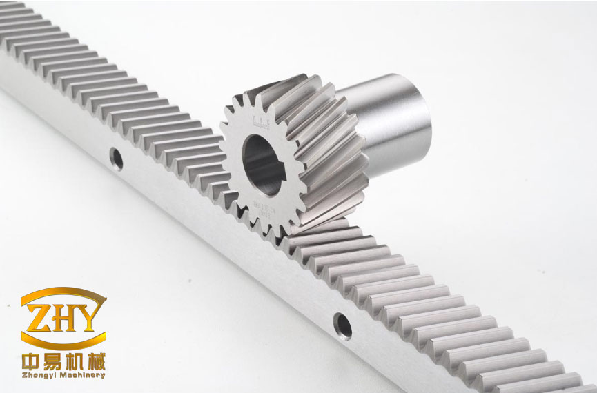
The rack and pinion gear mechanism in my study is part of a long-travel feed axis. A servo motor supplies torque through a reducer to a helical pinion. The pinion rotates and meshes with a fixed rack, so the pinion translates and drives the load. This configuration differs from ball-screw feed drives because the rack and pinion gear contact is distributed along the tooth width, and the helical angle introduces a gradual engagement and disengagement process. I therefore include the helical rack and pinion gear meshing characteristics directly in the dynamic model. The main parameters of the helical rack and pinion gear pair are listed in Table 1.
| Parameter | Symbol | Value |
|---|---|---|
| Normal module | \(m_n\) | 2 mm |
| Normal pressure angle | \(\alpha_n\) | 20° |
| Helix angle | \(\beta\) | 19.5283° |
| Number of teeth | \(N_1\) | 30 |
| Face width | \(B\) | 28 mm |
| Young’s modulus | \(E\) | \(2.06\times 10^{11}\) Pa |
| Poisson ratio | \(\nu\) | 0.25 |
| Pinion mass | \(m\) | 0.7 kg |
I use a lumped-parameter method to represent the rack and pinion gear feed system. The motor inertia, pinion inertia, pinion mass, and load mass are treated as separate degrees of freedom. The reducer is modeled as a torsional spring and damper, and the connection between the pinion and the load is modeled as a translational spring and damper. The dynamic equations of the mechanical subsystem are written as
$$
\begin{aligned}
J_{mx}\ddot{\theta}_{mx} &= T_{ex}-k_{rx}\left(\theta_{mx}-i_x\theta_{gx}\right)-c_{rx}\left(\dot{\theta}_{mx}-i_x\dot{\theta}_{gx}\right),\\
J_{gx}\ddot{\theta}_{gx} &= i_x\left[k_{rx}\left(\theta_{mx}-i_x\theta_{gx}\right)+c_{rx}\left(\dot{\theta}_{mx}-i_x\dot{\theta}_{gx}\right)\right]-f_{nx}r_{gx},\\
m_{gx}\ddot{x}_{gx} &= f_{nx}-k_{sx}\left(x_{gx}-x_{lx}\right)-c_{sx}\left(\dot{x}_{gx}-\dot{x}_{lx}\right),\\
m_{lx}\ddot{x}_{lx} &= k_{sx}\left(x_{gx}-x_{lx}\right)+c_{sx}\left(\dot{x}_{gx}-\dot{x}_{lx}\right)-f_{lx}.
\end{aligned}
$$
In these equations, \(T_{ex}\) is the driving torque supplied by the motor to the mechanical system, \(J_{mx}\) is the motor inertia, \(J_{gx}\) is the pinion inertia, \(\theta_{mx}\) is the motor angle, \(\theta_{gx}\) is the pinion angle, \(i_x\) is the reduction ratio, \(k_{rx}\) and \(c_{rx}\) are the torsional stiffness and damping of the reducer, \(m_{gx}\) is the pinion mass, \(x_{gx}\) is the pinion translation, \(m_{lx}\) is the load mass, \(x_{lx}\) is the load translation, \(k_{sx}\) and \(c_{sx}\) are the support stiffness and damping, \(f_{lx}\) is the load resistance, and \(f_{nx}\) is the dynamic meshing force of the helical rack and pinion gear pair. The dynamic meshing force is expressed as
$$
f_{nx}=k_{nx}\cos\alpha_n\left(r_{gx}\theta_{gx}-x_{gx}-e_{nx}\cos\alpha_n\right)
+c_{nx}\cos\alpha_n\left(r_{gx}\dot{\theta}_{gx}-\dot{x}_{gx}-\dot{e}_{nx}\cos\alpha_n\right),
$$
where \(k_{nx}\) is the normal time-varying meshing stiffness, \(c_{nx}\) is the normal meshing damping, \(r_{gx}\) is the pitch radius of the pinion, and \(e_{nx}\) is the meshing error of the helical rack and pinion gear pair. The mechanical parameters used in my model are summarized in Table 2.
| Parameter | Symbol | Value |
|---|---|---|
| Motor inertia | \(J_{mx}\) | \(1.7\times 10^{-5}\ \mathrm{kg\cdot m^2}\) |
| Pinion inertia | \(J_{gx}\) | \(3.7703\times 10^{-4}\ \mathrm{kg\cdot m^2}\) |
| Pinion mass | \(m_{gx}\) | 0.7 kg |
| Load mass | \(m_{lx}\) | 300 kg |
| Reducer torsional stiffness | \(k_{rx}\) | \(24064\ \mathrm{N\cdot m\cdot rad^{-1}}\) |
| Support stiffness | \(k_{sx}\) | \(4.843\times 10^9\ \mathrm{N\cdot m^{-1}}\) |
| Reducer torsional damping | \(c_{rx}\) | \(0.041\ \mathrm{N\cdot m\cdot s\cdot rad^{-1}}\) |
| Support damping | \(c_{sx}\) | \(3489.7\ \mathrm{N\cdot s\cdot m^{-1}}\) |
| Reduction ratio | \(i_x\) | 50 |
The time-varying meshing stiffness of the helical rack and pinion gear pair is obtained by a potential-energy method combined with a slicing-integrating method. Because the helical pinion engages gradually along the tooth width, I divide the contact line into a number of slices. For each slice, I calculate the bending compliance, shear compliance, axial compression compliance, Hertzian contact compliance, and fillet-foundation compliance. I then integrate the slice contributions along the contact line to obtain the total meshing stiffness. This procedure is necessary because a rack and pinion gear pair with helical teeth does not enter and leave contact instantaneously. The bending compliance term is written as
$$
\frac{1}{k_b}=\sum_{i=1}^{N}\int_{-\alpha’_1}^{\alpha_2}
\frac{3\cos\alpha\left(\alpha_2-\alpha\right)
\left[1+\cos\alpha’_1\left(\left(\alpha_2-\alpha\right)\sin\alpha-\cos\alpha\right)\right]^2}
{2E\Delta z\left[\sin\alpha+\left(\alpha_2-\alpha\right)\cos\alpha\right]^3}\,d\alpha .
$$
The shear compliance term is
$$
\frac{1}{k_s}=\sum_{i=1}^{N}\int_{-\alpha’_1}^{\alpha_2}
\frac{1.2\left(1+\nu\right)\left(\alpha_2-\alpha\right)\cos\alpha\cos^2\alpha’_1}
{E\Delta z\left[\sin\alpha+\left(\alpha_2-\alpha\right)\cos\alpha\right]}\,d\alpha .
$$
The axial compression compliance term is
$$
\frac{1}{k_a}=\sum_{i=1}^{N}\int_{-\alpha’_1}^{\alpha_2}
\frac{\left(\alpha_2-\alpha\right)\cos\alpha\sin^2\alpha’_1}
{2E\Delta z\left[\sin\alpha+\left(\alpha_2-\alpha\right)\cos\alpha\right]}\,d\alpha .
$$
The Hertzian contact stiffness is
$$
k_h=\frac{\pi E L_{ct}}{4\left(1-\nu^2\right)}.
$$
The fillet-foundation stiffness is
$$
k_f=\frac{E\Delta z}{\cos^2\alpha’_1}
\left[
L\left(\frac{\mu_f}{s_f}\right)^2
+M\left(\frac{\mu_f}{s_f}\right)
+P\left(1+Q\tan\alpha’_1\right)
\right]^{-1}.
$$
In the above expressions, \(N\) is the number of slices, \(\Delta z\) is the projected slice length along the face width, \(L_{ct}\) is the length of the contact line, \(\alpha’_1\) is the angle between the meshing force and the tangent direction of the pinion, \(\alpha_2\) is the half-tooth angle at the base circle, and \(\mu_f\), \(s_f\), \(L\), \(M\), \(P\), and \(Q\) are geometric parameters of the fillet foundation. For a single tooth pair, the total compliance is the sum of the individual compliances:
$$
\frac{1}{k_{\mathrm{pair}}}
=
\frac{1}{k_b}
+\frac{1}{k_s}
+\frac{1}{k_a}
+\frac{1}{k_h}
+\frac{1}{k_f}.
$$
The time-varying meshing stiffness of the helical rack and pinion gear pair is then obtained by combining the contributions of all tooth pairs that are simultaneously in contact. I verify the average meshing stiffness by comparing it with a standard value. The comparison is given in Table 3. The error is only 1.67 %, which supports the use of the potential-energy and slicing-integrating method for the helical rack and pinion gear pair.
| Quantity | Value |
|---|---|
| Standard average meshing stiffness | \(5.009\times 10^8\ \mathrm{N\cdot m^{-1}}\) |
| Potential-energy and slicing-integrating result | \(5.0925\times 10^8\ \mathrm{N\cdot m^{-1}}\) |
| Absolute difference | \(0.0835\times 10^8\ \mathrm{N\cdot m^{-1}}\) |
| Relative error | 1.67 % |
The meshing error of the rack and pinion gear pair is an internal excitation that cannot be neglected. I represent it as a superposition of sinusoidal components associated with the shaft frequency and the meshing frequency:
$$
e(t)=\frac{1}{2}F_p\sin\left(2\pi f_a t+\phi_a\right)
+\frac{1}{2}f’\sin\left(2\pi f_m t+\phi_m\right).
$$
Here, \(F_p\) is the total cumulative pitch deviation, \(f’\) is the single-tooth tangential composite deviation, \(f_a\) is the shaft frequency, \(f_m\) is the meshing frequency, and \(\phi_a\) and \(\phi_m\) are initial phases. For a six-grade accuracy helical rack and pinion gear pair, I use \(F_p=26\ \mu\mathrm{m}\) and \(f’=10.24\ \mu\mathrm{m}\). These values produce a periodic internal excitation that directly affects the dynamic transmission error of the feed system. The meshing error is therefore one of the central quantities in my analysis of the rack and pinion gear feed system.
I first simulate the mechanical subsystem alone to identify the effect of the internal excitation. The motor torque is set to a constant value of \(0.64\ \mathrm{N\cdot m}\), and the load resistance is set to balance the drive. The target load speed is \(50\ \mathrm{mm/s}\). The simulation is solved with an explicit ordinary-differential-equation solver. When the mechanical system reaches a steady state, the load displacement error is periodic with a magnitude on the order of micrometers. The spectral analysis of the load displacement shows that the dominant low-frequency components are the shaft frequency and the meshing frequency of the rack and pinion gear pair. This result confirms that the time-varying meshing stiffness and the meshing error of the rack and pinion gear pair are the main internal excitations in the mechanical subsystem.
The electrical subsystem is modeled as an alternating-current synchronous servo motor with vector control. I use a double closed-loop structure with an outer speed loop and inner current loops. The three-phase natural coordinate system is transformed into a two-phase stationary coordinate system by the Clark transformation, and then into a two-phase rotating coordinate system by the Park transformation. The Clark transformation matrix is
$$
T_{\mathrm{Clark}}=
\frac{2}{3}
\begin{bmatrix}
1 & -\frac{1}{2} & -\frac{1}{2}\\[4pt]
0 & \frac{\sqrt{3}}{2} & -\frac{\sqrt{3}}{2}\\[4pt]
\frac{\sqrt{2}}{2} & \frac{\sqrt{2}}{2} & \frac{\sqrt{2}}{2}
\end{bmatrix}.
$$
The Park transformation matrix is
$$
T_{\mathrm{Park}}=
\begin{bmatrix}
\cos\theta_e & \sin\theta_e\\
-\sin\theta_e & \cos\theta_e
\end{bmatrix},
$$
where \(\theta_e\) is the electrical angle of the motor rotor. The inverse transformations are used to convert the command voltages in the rotating coordinate system back to the three-phase natural coordinate system. The voltage equations of the permanent-magnet synchronous motor in the \(d\)-\(q\) rotating coordinate system are
$$
u_d=R i_d+L_d\frac{di_d}{dt}-p_n\omega_m L_q i_q,
$$
$$
u_q=R i_q+L_q\frac{di_q}{dt}+p_n\omega_m\left(L_d i_d+\psi_f\right),
$$
where \(u_d\) and \(u_q\) are the stator voltages, \(i_d\) and \(i_q\) are the stator currents, \(L_d\) and \(L_q\) are the inductances, \(R\) is the stator resistance, \(p_n\) is the number of pole pairs, \(\omega_m\) is the mechanical angular speed, and \(\psi_f\) is the permanent-magnet flux linkage. The electromagnetic torque is
$$
T_e=\frac{3}{2}p_n i_q\left[i_d\left(L_d-L_q\right)+\psi_f\right].
$$
The mechanical equation of the motor shaft is
$$
J_m\frac{d\omega_m}{dt}=T_e-T_L-B\omega_m,
$$
where \(J_m\) is the equivalent motor inertia, \(T_L\) is the load torque, and \(B\) is the viscous damping coefficient. The speed loop and current loops use proportional-integral controllers. The speed-loop command is
$$
i_q^*=K_{p\omega}\left(\omega^*-\omega_m\right)
+K_{i\omega}\int\left(\omega^*-\omega_m\right)dt,
$$
and the current-loop commands are
$$
u_q^*=K_{pi_q}\left(i_q^*-i_q\right)
+K_{ii_q}\int\left(i_q^*-i_q\right)dt,
$$
$$
u_d^*=K_{pi_d}\left(i_d^*-i_d\right)
+K_{ii_d}\int\left(i_d^*-i_d\right)dt.
$$
The motor parameters that I use in the simulation are given in Table 4. These parameters correspond to a servo motor suitable for a large rack and pinion gear feed axis. The magnetic saliency is small, so \(L_d\) and \(L_q\) are close to each other.
| Parameter | Symbol | Value |
|---|---|---|
| \(d\)-axis inductance | \(L_d\) | \(0.02682\ \mathrm{H}\) |
| \(q\)-axis inductance | \(L_q\) | \(0.02682\ \mathrm{H}\) |
| Stator resistance | \(R\) | \(18.7\ \Omega\) |
| Motor inertia | \(J_m\) | \(1.7\times 10^{-5}\ \mathrm{kg\cdot m^2}\) |
| Number of pole pairs | \(p_n\) | 2 |
| Permanent-magnet flux linkage | \(\psi_f\) | \(0.1717\ \mathrm{V\cdot s\cdot rad^{-1}}\) |
| Speed-loop proportional gain | \(P_\omega\) | 0.013 |
| \(q\)-axis current-loop proportional gain | \(P_{iq}\) | 200 |
| \(d\)-axis current-loop proportional gain | \(P_{id}\) | 200 |
| Speed-loop integral gain | \(I_\omega\) | 1.3 |
| \(d\)-axis current-loop integral gain | \(I_{id}\) | 10000 |
| \(q\)-axis current-loop integral gain | \(I_{iq}\) | 10000 |
I test the motor model by applying a speed step and a load step. The initial speed is \(500\ \mathrm{r/min}\) and the initial load is \(0.2\ \mathrm{N\cdot m}\). After a short time, the speed command changes to \(750.73\ \mathrm{r/min}\), and later the load changes to \(0.64\ \mathrm{N\cdot m}\). The motor reaches the commanded speed and torque within approximately \(0.05\ \mathrm{s}\). The maximum overshoot is about 2.6 %, the peak time is about \(1.3\ \mathrm{ms}\), and the rise time and settling time are about \(20\ \mathrm{ms}\). The speed spectrum contains a fundamental component at \(150\ \mathrm{Hz}\) and several harmonics. These electrical frequency components are later compared with the mechanical frequency components of the rack and pinion gear feed system.
After validating the mechanical and electrical models separately, I couple them into an electromechanical system. The motor speed is passed to the mechanical subsystem, and the load torque computed from the mechanical subsystem is fed back to the motor. This creates a closed-loop model in which the dynamics of the rack and pinion gear pair influence the motor current and speed, and the motor control dynamics influence the meshing force and transmission error. The coupled system is solved in a simulation environment with the same solver used for the individual models.
In the coupled simulation, the motor speed command is \(750.73\ \mathrm{r/min}\), which corresponds to an ideal load speed of \(50\ \mathrm{mm/s}\). The load resistance is \(313.6\ \mathrm{N}\). After \(10\ \mathrm{s}\), the ideal load displacement is \(500\ \mathrm{mm}\), and the simulated load displacement is very close to this value. However, because of electromechanical inertia, the simulated displacement lags the command displacement. The lag is on the order of \(10^{-5}\ \mathrm{m}\) when no meshing error is included. When the meshing error of the rack and pinion gear pair is included, the fluctuation amplitude of the displacement error becomes much larger. This shows that the meshing error of the rack and pinion gear pair is a leading contributor to the dynamic transmission error.
I analyze the load acceleration and load displacement spectra of the coupled system. The load acceleration spectrum contains the shaft frequency, the meshing frequency of the rack and pinion gear pair, the motor fundamental frequency, the motor harmonics, and modulation sidebands around the meshing frequency. This means that the rack and pinion gear feed system is simultaneously affected by mechanical and electrical excitations. In the load displacement spectrum, however, the shaft frequency and the meshing frequency have much larger amplitudes than the motor fundamental and its harmonics. The motor frequency at \(150\ \mathrm{Hz}\) is visible in the acceleration spectrum but is not a dominant component in the displacement spectrum. Therefore, for the displacement error of this rack and pinion gear feed system, the rack and pinion gear meshing behavior is more important than the high-frequency motor ripple.
To study the influence of operating speed, I repeat the electromechanical simulation at several load speeds. The meshing frequency of the rack and pinion gear pair scales with the pinion speed, and the shaft frequency scales in the same way. The motor fundamental frequency remains tied to the electrical speed. The simulation results show that the dominant displacement-error frequencies are the shaft frequency and the meshing frequency for all tested speeds. The modulation sidebands become more complex at higher speeds because the meshing frequency approaches the motor harmonic frequencies. This interaction is a characteristic feature of a motor-driven rack and pinion gear feed system.
I also perform experiments on a machine tool feed axis driven by a helical rack and pinion gear. The experimental system consists of the machine tool, the electrical control cabinet, and a host computer that sends motion commands. The host computer generates the position and speed commands, the controller performs motion planning and closed-loop control, and the drive signals are sent to the servo motor. The pinion then rotates along the fixed rack and moves the load. The tested axis is the \(x\)-axis of the machine, and the transmission is a helical rack and pinion gear pair.
During the experiments, I command the load to move at constant speeds of \(30\ \mathrm{mm/s}\), \(40\ \mathrm{mm/s}\), \(50\ \mathrm{mm/s}\), \(60\ \mathrm{mm/s}\), and \(70\ \mathrm{mm/s}\). For each speed, I record the load displacement and compare it with the ideal commanded displacement. At \(50\ \mathrm{mm/s}\), the initial coordinate is \(100\ \mathrm{mm}\) and the final coordinate is \(400\ \mathrm{mm}\). The experimental displacement lags the command displacement because of system inertia and control tracking error. After removing the steady offset, the displacement error fluctuates around a mean value of about \(4.04\times 10^{-4}\ \mathrm{m}\), and the fluctuation amplitude decreases as the motion becomes more stable.
I perform spectral analysis on the experimental displacement after removing the direct-current component. The low-frequency components include the shaft frequency \(f_a\), the meshing frequency \(f_m\), half of the meshing frequency, twice the meshing frequency, the motor rotational frequency \(f_r\), and twice the motor rotational frequency. The two largest peaks are the shaft frequency and the meshing frequency of the rack and pinion gear pair. This agrees with my simulation conclusion that the rack and pinion gear meshing error is the main error source in the feed system.
For the \(50\ \mathrm{mm/s}\) case, the theoretical meshing frequency is \(7.5\ \mathrm{Hz}\) and the theoretical shaft frequency is \(0.25\ \mathrm{Hz}\). For the other tested speeds, the frequencies scale proportionally. The measured dominant frequencies are listed in Table 5. In every case, the largest two frequencies correspond to the shaft frequency and the meshing frequency of the rack and pinion gear pair. This consistency across speeds strongly supports the conclusion that the rack and pinion gear meshing excitation dominates the dynamic transmission error.
| Load speed | Largest frequency | Second largest frequency |
|---|---|---|
| \(30\ \mathrm{mm/s}\) | \(4.471\ \mathrm{Hz}\) | \(0.149\ \mathrm{Hz}\) |
| \(40\ \mathrm{mm/s}\) | \(5.998\ \mathrm{Hz}\) | \(0.1996\ \mathrm{Hz}\) |
| \(50\ \mathrm{mm/s}\) | \(7.481\ \mathrm{Hz}\) | \(0.2494\ \mathrm{Hz}\) |
| \(60\ \mathrm{mm/s}\) | \(9.063\ \mathrm{Hz}\) | \(0.3021\ \mathrm{Hz}\) |
| \(70\ \mathrm{mm/s}\) | \(10.41\ \mathrm{Hz}\) | \(0.3717\ \mathrm{Hz}\) |
The experimental results also show that the amplitude ratio between the shaft frequency and the meshing frequency depends on the assumed meshing-error coefficients. In the initial model, I used the maximum cumulative pitch deviation directly. The experimental spectrum suggests that the effective shaft-frequency amplitude is smaller than the maximum value. When I scale the shaft-frequency coefficient to about one quarter of the maximum cumulative pitch deviation, the simulated amplitude ratio between the shaft frequency and the meshing frequency becomes closer to the measured ratio. This correction does not change the main conclusion; it only improves the quantitative agreement between the model and the experiment.
The dynamic error of the rack and pinion gear feed system can be summarized by the following relation:
$$
\varepsilon_{\mathrm{total}}
=
\varepsilon_{\mathrm{motor}}
+
\varepsilon_{\mathrm{control}}
+
\varepsilon_{\mathrm{structure}}
+
\varepsilon_{\mathrm{rack-pinion}},
$$
where \(\varepsilon_{\mathrm{motor}}\) is the error caused by motor torque ripple and electrical dynamics, \(\varepsilon_{\mathrm{control}}\) is the tracking error of the closed-loop controller, \(\varepsilon_{\mathrm{structure}}\) is the deformation of the support and reducer, and \(\varepsilon_{\mathrm{rack-pinion}}\) is the transmission error caused by the rack and pinion gear meshing stiffness and meshing error. My simulation and experiment indicate that \(\varepsilon_{\mathrm{rack-pinion}}\) is the largest term for the studied feed system. This is why I place so much emphasis on the rack and pinion gear model.
The time-varying meshing stiffness of the rack and pinion gear pair also influences the dynamic response. When the contact ratio changes, the number of teeth in contact changes, and the effective stiffness fluctuates. In a helical rack and pinion gear pair, the gradual engagement along the helix reduces the abruptness of the stiffness change, but it does not eliminate the fluctuation. The fluctuation produces a periodic meshing force that excites the load and support. The meshing damping also affects the amplitude of the dynamic force. In my model, the normal meshing damping is calculated from the meshing stiffness, equivalent mass, and a damping ratio. The dynamic meshing force then acts on the pinion and rack through the pressure angle.
I can express the equivalent transmission error of the rack and pinion gear pair as
$$
x_{\mathrm{te}}
=
r_{gx}\theta_{gx}-x_{gx}.
$$
The dynamic meshing force can then be rewritten in a compact form:
$$
f_{nx}
=
k_{nx}\cos\alpha_n\left(x_{\mathrm{te}}-e_{nx}\cos\alpha_n\right)
+
c_{nx}\cos\alpha_n\left(\dot{x}_{\mathrm{te}}-\dot{e}_{nx}\cos\alpha_n\right).
$$
This compact form shows that both the transmission error and the meshing error contribute to the dynamic force. The meshing error acts as an internal displacement excitation, while the transmission error acts as a dynamic response. The coupling between them creates the frequency components observed in the simulation and experiment. The shaft frequency appears because the meshing error repeats once per pinion revolution, and the meshing frequency appears because the tooth contact repeats once per tooth engagement.
The motor control loop also has an effect on the dynamic error. When the load torque changes because of the rack and pinion gear meshing force, the speed loop adjusts the \(q\)-axis current command. The current loop then changes the motor torque. This closed-loop action can reduce low-frequency speed error, but it can also introduce modulation sidebands. The sidebands appear around the meshing frequency and its harmonics, and they are separated from the meshing frequency by the motor electrical frequency. In my acceleration spectrum, these sidebands are visible, but their amplitudes are smaller than the main meshing component. For displacement error, the sidebands are even less significant.
The choice of helix angle in the rack and pinion gear pair is important. A larger helix angle increases the contact ratio and makes the load transfer smoother, but it also increases the axial force. The axial force must be supported by the bearing and guide system. If the axial stiffness is insufficient, the pinion may shift along the rack, which changes the contact pattern and increases the transmission error. In my model, the axial degree of freedom is not explicitly included, but the radial and tangential meshing force components are represented through the pressure angle and the helix angle. For a more detailed design, I would add the axial displacement of the pinion and the bearing stiffness in the axial direction.
The rack and pinion gear support stiffness also affects the dynamic response. The support stiffness between the pinion and the load is very high in my model, so the pinion and load move almost together at low frequencies. However, at higher frequencies, the support compliance can create relative motion and additional resonances. The reducer torsional stiffness is lower than the support stiffness, so the motor and pinion can oscillate relative to each other. The first torsional mode of the motor-reducer-pinion system may be excited by the meshing force if the meshing frequency or its harmonics coincide with that mode. In my simulations, the operating speed range does not place the meshing frequency exactly on the torsional resonance, but the sidebands can still approach it at higher speeds.
I also examine the effect of load mass. A larger load mass increases the inertia of the feed system and reduces the high-frequency response. It also increases the time constant of the speed loop. In the rack and pinion gear feed system, the load mass is much larger than the pinion mass, so the load dominates the translational dynamics. The pinion inertia is smaller but still significant because of the reducer ratio. The equivalent inertia referred to the motor shaft includes the motor inertia, the pinion inertia divided by the square of the reduction ratio, and the load mass divided by the square of the equivalent rack and pinion gear ratio. This equivalent inertia determines the motor torque required for a given acceleration.
The equivalent rack and pinion gear ratio from pinion rotation to load translation is
$$
r_{\mathrm{eq}}=r_{gx}.
$$
Therefore, the load force referred to the pinion torque is
$$
T_{\mathrm{load}}=f_{lx}r_{gx}.
$$
When this torque is referred to the motor shaft through the reducer, it becomes
$$
T_{\mathrm{load,motor}}=\frac{f_{lx}r_{gx}}{i_x}.
$$
These relations are used in the coupled simulation to feed the mechanical load torque back to the motor model. They also show that the reducer ratio strongly reduces the load torque seen by the motor, but it also reduces the load speed seen by the motor. The rack and pinion gear pair therefore operates at a relatively low speed and high torque compared with the motor shaft.
For design purposes, I summarize the main factors that influence the dynamic transmission error of the rack and pinion gear feed system in Table 6. The table lists the factor, its physical origin, and its expected effect. This summary is based on my simulation and experimental observations.
| Factor | Physical origin | Effect on dynamic error |
|---|---|---|
| Total cumulative pitch deviation | Manufacturing error of the rack and pinion gear | Produces shaft-frequency displacement error |
| Single-tooth tangential composite deviation | Tooth profile and spacing error | Produces meshing-frequency displacement error |
| Time-varying meshing stiffness | Changing number of teeth in contact | Modulates the meshing force and acceleration |
| Helix angle | Gradual contact along the tooth width | Smoothes load transfer but introduces axial force |
| Support stiffness | Bearing and guide compliance | Changes high-frequency response and resonance |
| Reducer torsional stiffness | Shaft and coupling compliance | Creates motor-pinion torsional oscillation |
| Motor current-loop bandwidth | Electrical control dynamics | Affects torque ripple and sidebands |
| Speed-loop bandwidth | Outer control loop | Affects tracking error and low-frequency stability |
| Load mass | Moving machine component | Changes inertia and settling time |
| Meshing damping | Lubrication and contact loss | Reduces amplitude of meshing oscillation |
My experimental results confirm that the rack and pinion gear meshing error is the main source of dynamic transmission error. The frequency-domain signature of the error contains the shaft frequency and the meshing frequency as the two largest components. The motor fundamental and its harmonics are present but weaker in the displacement spectrum. The modulation sidebands show that the motor and the rack and pinion gear interact, but the interaction does not change the main ranking of error sources. This finding is useful for the design of high-precision rack and pinion gear feed systems because it suggests that improving the manufacturing accuracy of the rack and pinion gear pair will produce a larger benefit than increasing the motor bandwidth alone.
I also note that the dynamic error of the rack and pinion gear feed system is not simply the sum of static errors. Static errors such as straightness, perpendicularity, and backlash affect the initial accuracy, but the dynamic error is produced by the interaction of inertia, stiffness, damping, control, and meshing excitation. A rack and pinion gear pair that is accurate in a static measurement can still produce a large dynamic error if its meshing stiffness varies strongly or if its meshing error contains a large component at the shaft frequency. Therefore, dynamic testing at several feed speeds is necessary. In my experiments, the dominant frequencies scale with speed, and the amplitude ratio between the shaft frequency and the meshing frequency remains similar. This behavior is consistent with a meshing-error-dominated mechanism.
For future improvement, I would consider several modifications. First, I would reduce the cumulative pitch deviation and the single-tooth tangential composite deviation of the rack and pinion gear pair through finer machining and grinding. Second, I would optimize the helix angle and contact ratio to reduce the fluctuation of the meshing stiffness. Third, I would increase the support stiffness and the reducer torsional stiffness to move the resonances away from the operating frequency range. Fourth, I would tune the speed loop and current loops to avoid creating sidebands near the meshing frequency. Fifth, I would add measured meshing error data instead of using a simple sinusoidal representation. These steps would improve the dynamic accuracy of the rack and pinion gear feed system.
The main conclusions of my study can be stated as follows. The rack and pinion gear meshing error is the dominant error source in the motor-driven feed system. The dynamic transmission error is a periodic function whose main frequency components are the shaft frequency and the meshing frequency of the rack and pinion gear pair. The motor fundamental frequency and its harmonics appear in the acceleration spectrum and produce modulation sidebands, but their influence on the displacement error is smaller than that of the rack and pinion gear meshing excitation. The time-varying meshing stiffness and meshing error must both be included to reproduce the measured dynamic behavior. The electromechanical coupling model that I developed is able to predict the main frequency components and the relative importance of the error sources.
In summary, I have presented a dynamic analysis of a motor-helical rack and pinion gear feed system for computer numerical control machines. I used a potential-energy method and a slicing-integrating method to obtain the time-varying meshing stiffness of the helical rack and pinion gear pair. I included the meshing error as an internal excitation. I built a vector-controlled alternating-current synchronous servo motor model with speed and current loops. I coupled the motor model with the rack and pinion gear dynamics and validated the coupled model through simulation and experiment. The results show that the rack and pinion gear error is the main error source and that the shaft frequency and meshing frequency are the most important frequency components. These findings provide a basis for designing high-dynamic-precision rack and pinion gear feed systems.