
In intersecting shaft transmission, spiral bevel gear has the advantages of large bearing capacity, low noise and stable transmission. With the rapid growth of machinery manufacturing industry and the increasingly fierce competition in the international market, China has higher and higher requirements for the accuracy, noise and strength of spiral bevel gears. Liu Guanglei used Matlab to calculate the coordinate set of tooth surface points, and then imported it into ANSYS to establish the spiral bevel gear model. Zhou kaihong et al. Directly obtained the curve in UG by establishing the equation, and then constructed the tooth surface from the curve. Tang Jinyuan and others simulated the machining process of spiral bevel gear in AutoCAD, enveloped the tooth surface of spiral bevel gear with discrete “cutter path”, and then obtained the spiral bevel gear model through array. Direct modeling requires derivation of curve formulas and calculation of transition surfaces, which is not flexible. CATIA is used to simulate the machining of spiral bevel gears. The accuracy of the model not only meets the design requirements, but also the simulation cutting is similar to the actual machining scene, and the process is more intuitive and vivid. The finite element analysis of spiral bevel gear model and the adjustment parameters of machine tool according to the contact area and transmission error curve can better guide the design and production of spiral bevel gear.
The process of virtual simulation machining of spiral bevel gear with CATIA is as follows: studying the machine tool model and motion mode, establishing the tool and gear blank model, secondary development and gear cutting program programming of CATIA with VB, adjusting the gear blank and tool in the initial position of cutting, and virtual machining of spiral bevel gear.
1. Analysis of traditional machine tool model

According to the machine tool setting relationship and processing principle of traditional mechanical machine tools, the machine tool processing coordinate system shown in Figure 1 is established, in which so (XO, yo, Zo) is the machine tool coordinate system, SC (XC, YC, ZC) is the shaking table coordinate system, St (XT, YT, ZT) is the cutter head coordinate system, SP (XP, YP, ZP) is the workpiece coordinate system, Se (Xe, ye, Ze) is the coordinate system of the workpiece box, and SA (XA, ya, ZA) It is a coordinate system fixedly connected with the bed saddle. Its origin OA is (0, – em, XB,) in so (XO, yo, Zo), SQ (XQ, YQ, ZQ) parallel to the se coordinate system is the auxiliary coordinate system, its origin is (XA, 0, 0,) in se, the rotation angle of SC around ZC is the adjustment angle Q of the shaking table, and the rotation angle of SE around Ye is the cone angle of the installation root γ m. SP has a corner around XP Φ p. I is the total tool inclination; J is the basic tool angle; EM is the vertical wheel position; SD is the radial tool position; Xa is the horizontal wheel position; XB is the bed. Through the analysis of traditional machine tools and the research on the motion relationship of machine tools, it provides help for us to establish the machine tool model in CATIA in the next step.
2. Spiral bevel gear processing
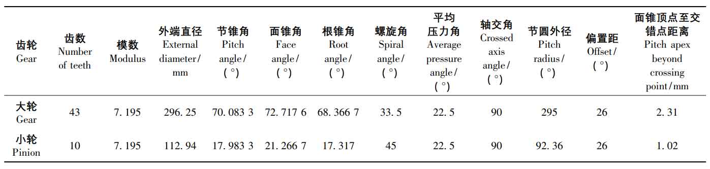
According to the position relationship of each part of the machine tool and the processing principle of spiral bevel gear, the large wheel is processed by forming method and the small wheel is processed by tool inclination method in CATIA. The blank parameters of spiral bevel gear are shown in Table 1, and the machine tool adjustment parameters of large wheel and small wheel are shown in Table 2 and table 3.

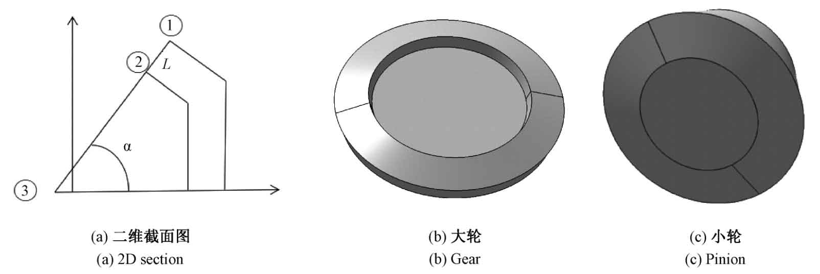
According to the basic parameters of spiral bevel gear in Table 1, the wheel blank is established in CATIA 3D software. The ordinate of point ① is the crown top distance, α Is the face cone angle, l is the tooth face width, and point ③ is the face cone point. Through these parameters, the two-dimensional cross-section of the wheel blank can be determined, and then the three-dimensional model of the wheel blank can be generated in CATIA, as shown in Figure 2. From left to right, there are large wheel blank and small wheel blank.
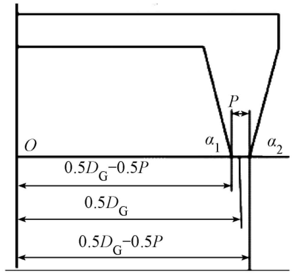
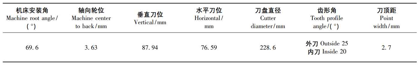
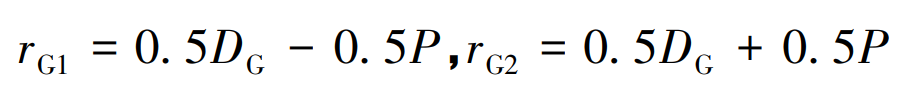
According to the cutter head parameters, the cutter model can be established in CATIA. The large wheel is processed by forming method, the cutter is double-sided cutter head, the small wheel is processed by cutter inclination method, the cutter is single-sided cutter head, and the concave convex surface of the small wheel is processed by external cutter and internal cutter respectively. The structure of double-sided cutter head is similar to that of single-sided cutter head. Only double-sided cutter head is introduced here. Determination of structural parameters of double-sided cutter head: as shown in Figure 3, α 1、 α 2 is the pressure angle of the inner knife and the outer knife respectively. The inner knife processes the convex surface of the big wheel and the outer knife processes the concave surface of the big wheel. Rg1 and Rg2 are the radius of inner and outer tool tips respectively, so it can be seen from the figure:
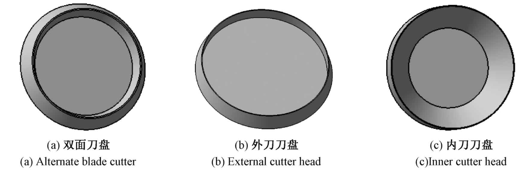
The tool model is established according to the above parameters, as shown in Figure 4, which are double-sided cutter head, outer cutter head and inner cutter head respectively.
According to the machine tool processing parameters and machine tool motion principle, the built wheel blank and tool model are placed in the correct position in CATIA. The position of large wheel and small wheel blank is determined according to the installation angle of machine tool, bed position, vertical wheel position, axial wheel position and other parameters. The principle and process of forming method are relatively simple. The principle and process of small wheel cutter tilting method are mainly introduced. According to Gleason No.116 gear milling machine, the small wheel cutter inclination cutting model is established. The installation position of the cutter is determined by the parameters such as total cutter inclination, basic cutter angle, radial cutter position and angular cutter position. As shown in Figure 5, the small wheel and the tool are at the initial position of cutting. The wheel blank and the tool move relative in CATIA according to the roll ratio of the machine tool. The two interfere. The process of cutting the gear blank by the tool is simulated by Boolean removal operation. In the CATIA gear cutting simulation process, the efficiency and convenience of gear cutting can be improved through macro recording operation and secondary development.
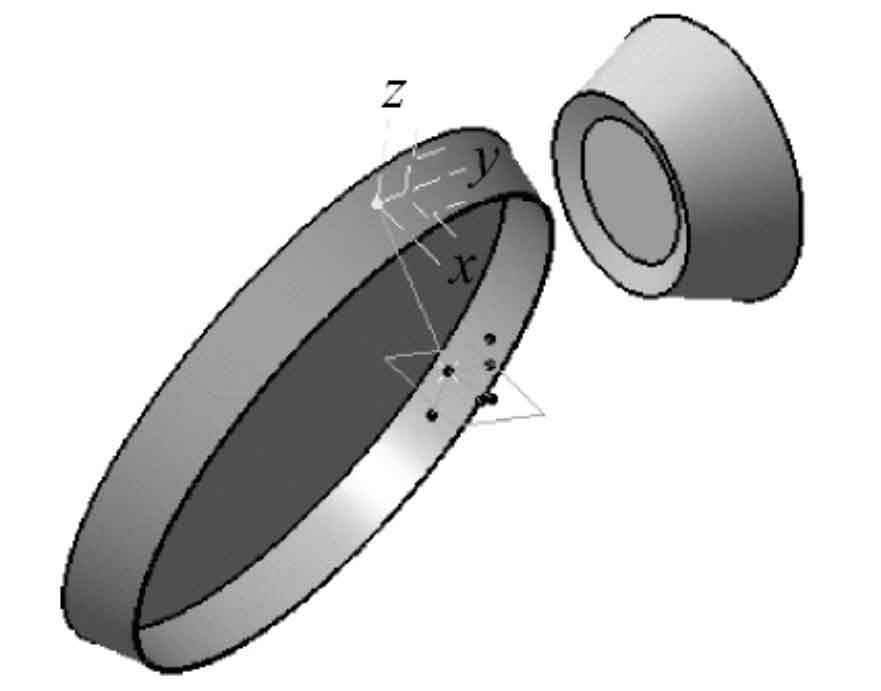
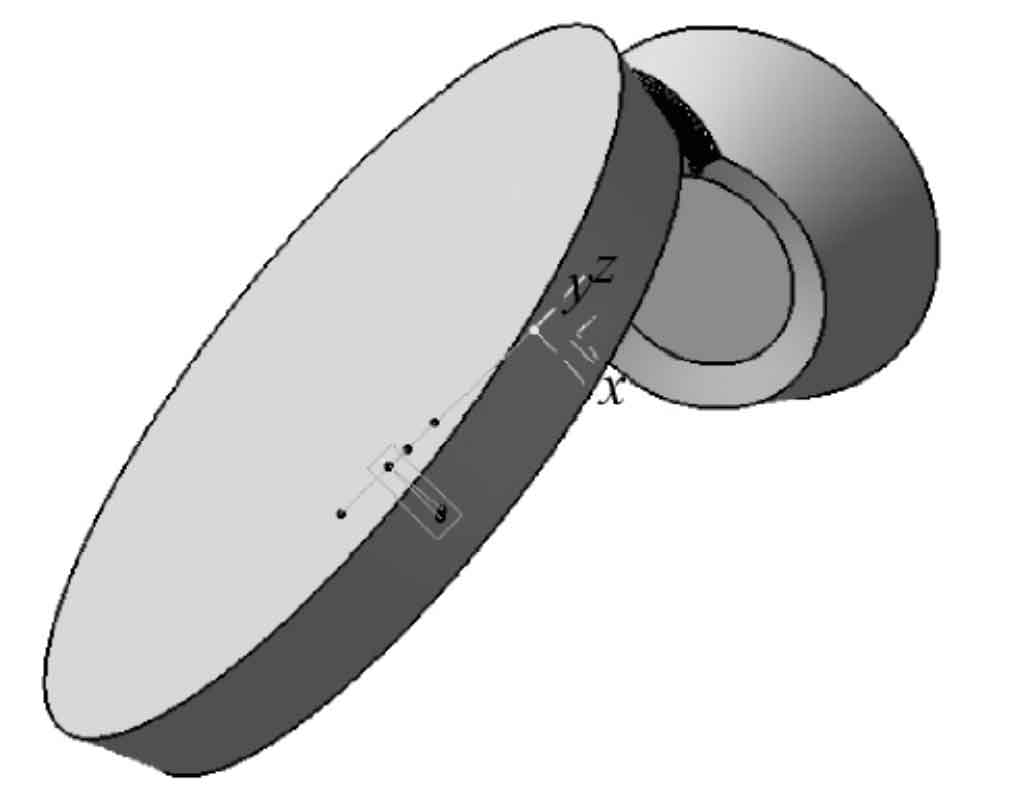
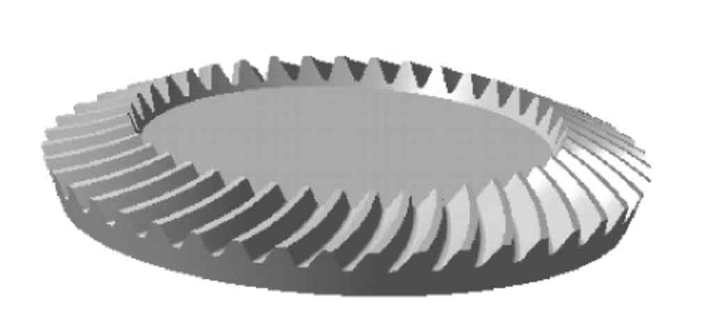
Fig. 6 shows the first tooth groove of the spiral bevel gear small wheel being cut by the tool inclination method. The small wheel and the large wheel after cutting are shown in Fig. 7 and Fig. 8 respectively.
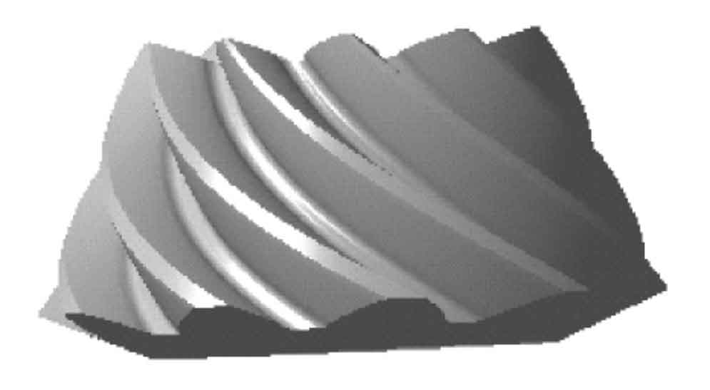
In order to verify the correctness of CATIA tooth cutting, the accuracy of tooth cutting needs to be verified. The theoretical point coordinates can be obtained by solving the nonlinear equations of the tooth surface, and then the theoretical point coordinates can be imported into CATIA. As shown in Fig. 9, the distance from the theoretical point to the spiral bevel gear tooth cutting surface is measured with the measuring tool in the software, It is found that the machining error of spiral bevel gear small wheel and large wheel is between -0.0002 mm and 0.0002 mm, which meets the accuracy requirements and proves the rationality of CATIA gear cutting. This way can be used to build the model of engineering analysis.