
In the intricate world of gear manufacturing, the production of spiral gears presents a unique set of challenges. The conventional method for hobbing these helical wonders often relies on a differential mechanism within the hobbing machine to synchronize the rotation of the workpiece with the axial feed of the hob, thereby generating the required helix. However, practical scenarios frequently arise where this standard method encounters obstacles. For instance, when the number of teeth on the workpiece and the machine’s indexing constant are not compatible for a simple calculation, or when the helix angle is so small that the calculated differential ratio becomes impractically large or incalculable. Traditionally, a non-differential hobbing method existed as a fallback, but it was often criticized for its inherent lack of precision compared to its differential counterpart. This compromise in accuracy is unacceptable for high-quality gear pairs. Today, I will elaborate on a refined non-differential hobbing technique that overcomes this critical limitation. This method achieves precision on par with differential hobbing, making it an invaluable tool, especially for machines that lack a differential mechanism entirely. The core innovation lies not in the machine’s hardware, but in a clever recalculation of the feed rate and gearing ratios.
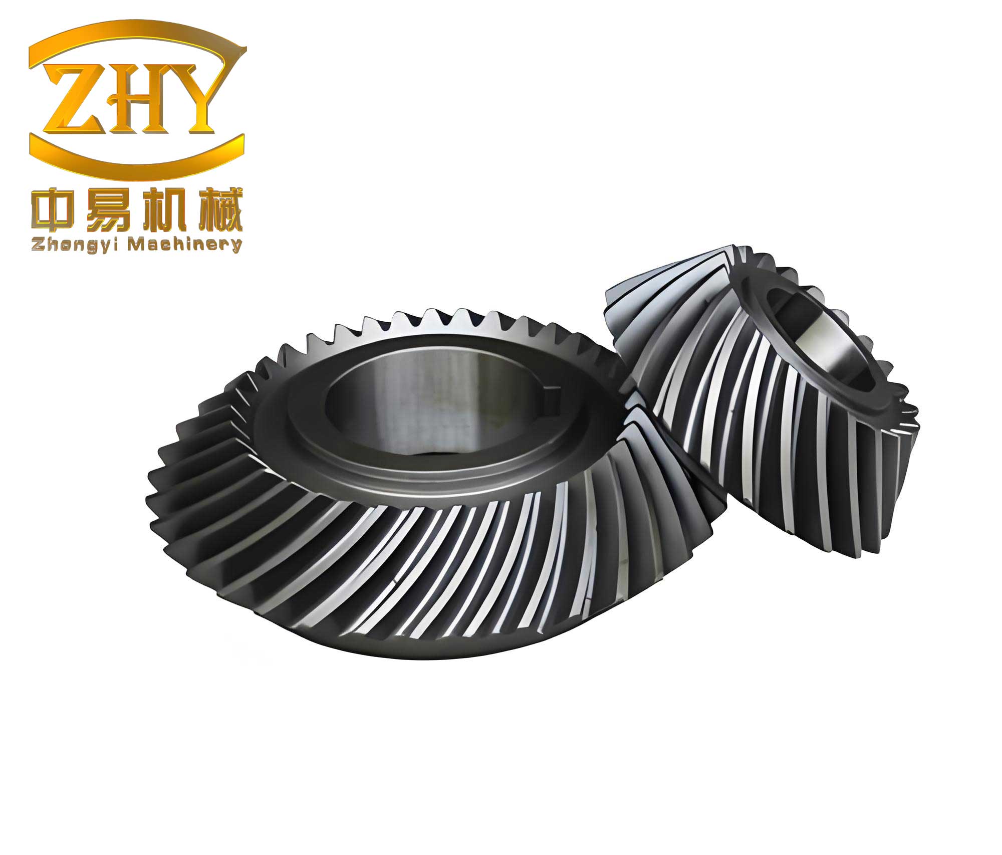
Let us first establish the fundamental kinematic relationship in hobbing. When cutting a spur gear with a single-start hob, the relationship is straightforward: for one full revolution of the hob, the workpiece must rotate by $1/z$ of a revolution, where $z$ is the number of teeth on the workpiece. However, for spiral gears, the axial movement of the hob relative to the workpiece directly influences its rotation to form the helix. If the hob were to travel axially by a distance equal to the lead $L$ of the workpiece helix without rotating the workpiece, the workpiece would, in theory, complete one revolution. In actual hobbing, we have a constant feed rate $s$ (mm per revolution of the workpiece). Therefore, for the workpiece to rotate one full revolution, the hob travels a distance $s$. The proportion of the lead covered in this movement is $s / L$. Consequently, the additional rotational component required from the workpiece due to the helix is this proportion of a full revolution.
In a standard mechanical hobbing machine model, the kinematic chain dictates that when the hob rotates through $K$ turns (where $K$ is the machine’s characteristic index constant), the workpiece should rotate through $1/z$ turns for indexing, plus the supplementary rotation for the helix. This combined relationship for non-differential hobbing can be initially expressed by the following formula, where $k$ is the number of starts on the hob:
$$ \frac{K}{z’} = \frac{k}{z} \pm \frac{s}{L} $$
Here, $z’$ represents the teeth of the change gears in the indexing train. The $\pm$ sign depends on the relative handedness of the hob and the workpiece: use $+$ when they are opposite, and $-$ when they are the same. The lead $L$ is related to the helical parameters by $L = \frac{\pi m_n z}{\sin \beta}$, where $m_n$ is the normal module and $\beta$ is the helix angle. Substituting this in, we get the classic non-differential indexing formula:
$$ \frac{K}{z’} = \frac{k}{z} \pm \frac{s \cdot \sin \beta}{\pi m_n z} \tag{1} $$
The principal drawback of this formula is that the term $\frac{s \cdot \sin \beta}{\pi m_n z}$ is typically a complex decimal. Calculating the change gear teeth $z’$ therefore necessitates an approximation. This approximation error is compounded when hobbing a mating pair of spiral gears. Since the indexing change gears must be different for the pinion and the gear, but are both approximated independently, their respective helix angle errors do not cancel out. This leads to a mismatch in the effective helix angles of the mating pair, degrading the quality of meshing and contact pattern.
The brilliance of the new method is to strategically manipulate the feed rate $s$ to eliminate this approximation error in the indexing calculation. We start by rearranging equation (1):
$$ \frac{K}{z’} = \frac{1}{z} \left( k \pm \frac{s \cdot \sin \beta}{\pi m_n} \right) \tag{2} $$
Let us denote the critical term as:
$$ A = k \pm \frac{s \cdot \sin \beta}{\pi m_n} $$
In the conventional approach, $A$ is a troublesome decimal. The new method proposes that we have the freedom to adjust the nominal feed rate $s$ within a practical range. We choose an adjusted feed value $s’$ such that the term $A$ becomes a rational number expressible as a simple fraction:
$$ A = k \pm \frac{s’ \cdot \sin \beta}{\pi m_n} = \frac{X}{Y} $$
Here, $X$ and $Y$ are integers. This is always possible by a suitable choice of $s’$. Substituting back into equation (2), we obtain:
$$ \frac{K}{z’} = \frac{1}{z} \cdot \frac{X}{Y} = \frac{X}{z \cdot Y} $$
Therefore, the indexing change gear ratio becomes:
$$ \frac{z’}{K} = \frac{z \cdot Y}{X} \tag{3} $$
Since $X$ and $Y$ are integers we deliberately chose, and $z$ and $K$ are known integers, the right-hand side of equation (3) is a rational number. This allows for the exact calculation of the indexing change gears without any approximation. The core task is the selection of the integers $X$ and $Y$. We start from the definition:
$$ \frac{X}{Y} = k \pm \frac{s’ \cdot \sin \beta}{\pi m_n} $$
We can choose a convenient integer $Y$ based on available change gears or desired precision. Then, we solve for the required feed rate $s’$ that satisfies the equation with an integer $X$:
$$ s’ = \frac{\pi m_n}{\sin \beta} \left( \frac{X}{Y} – k \right) \quad \text{(for the case using the ∓ sign, attention to sign is crucial)} $$
In practice, we first calculate the theoretical value $A$ using a desired $s$. Then, we find a simple fraction $X/Y$ that is a very close approximation to $A$. The quality of this approximation determines how little the feed rate $s’$ deviates from our initially desired value $s$. The following table outlines this decision and calculation process.
| Step | Action | Formula/Note |
|---|---|---|
| 1 | Calculate theoretical A | $A = k \pm \frac{s \cdot \sin \beta}{\pi m_n}$ |
| 2 | Find integer pair X, Y | Choose Y (e.g., from available gear teeth), then find $X = \text{round}(A \times Y)$. Alternatively, find the continued fraction of A. |
| 3 | Calculate adjusted feed s’ | $s’ = \left| \frac{\pi m_n}{\sin \beta} \left( \frac{X}{Y} – k \right) \right|$ |
| 4 | Verify s’ is practical | Check if $s’$ is within acceptable machine feed range. If not, adjust X/Y selection. |
| 5 | Calculate exact indexing gears | $\text{Ratio} = \frac{z \cdot Y}{X}$ (for the selected workpiece z) |
Now, we must address the feed change gears. The feed gear train on a typical machine, say a model 5A machine, follows its own formula. For a machine where the feed is coupled to the workpiece rotation, the relationship often takes the form:
$$ \frac{s’}{t} = \frac{a_f}{b_f} \cdot C_f \tag{4} $$
where $t$ is the pitch of the feed screw, $a_f$ and $b_f$ are the feed change gears, and $C_f$ is a constant specific to the feed gear train. Calculating $a_f$ and $b_f$ will generally involve an approximation because $s’$ is a specific value. However, and this is the second crucial point, when hobbing a mating pair of spiral gears (e.g., a pinion and a gear), we use the same adjusted feed rate $s’$ and consequently the same feed change gears for both members. Although the feed gears themselves are approximated, the error introduced is identical for both gears in the pair. This common error does not affect the relative kinematic relationship between them; it merely slightly alters the absolute value of the achieved helix angle for both by the same amount. Therefore, the helix angles of the mating spiral gears remain perfectly equal, ensuring correct meshing conditions. The absolute error in helix angle can be verified and is typically negligible.
Let’s solidify this understanding with a comprehensive example. Suppose we need to machine a pair of mating spiral gears on a machine akin to the model 5A. The parameters are as follows:
- Hob: Single-start ($k=1$), right-handed.
- Gear (Large Wheel): $z_g = 77$, right-handed helix, normal module $m_n = 2 \text{ mm}$, helix angle $\beta = 12^\circ 30’$.
- Pinion (Small Wheel): $z_p = 19$, left-handed helix, $m_n = 2 \text{ mm}$, $\beta = 12^\circ 30’$.
- Desired Feed: $s = 1.0 \text{ mm/rev}$.
- Machine Index Constant: Assume $K = 24$.
We will not use the differential. Our goal is to find the exact indexing and feed change gears.
Step 1: Calculate the theoretical factor A.
For the large gear (same hand as hob, use minus sign):
$$ A_g = 1 – \frac{1.0 \cdot \sin(12^\circ 30′)}{\pi \cdot 2} = 1 – \frac{1.0 \cdot 0.2164396}{6.283185} \approx 1 – 0.034453 \approx 0.965547 $$
For the small pinion (opposite hand to hob, use plus sign):
$$ A_p = 1 + \frac{1.0 \cdot \sin(12^\circ 30′)}{\pi \cdot 2} = 1 + 0.034453 \approx 1.034453 $$
Step 2: Choose integer pairs X/Y.
We need simple fractions close to these values. Let’s choose a denominator $Y = 40$ for both for simplicity (in practice, availability guides this).
For $A_g \approx 0.965547$: $X_g = \text{round}(0.965547 \times 40) = \text{round}(38.62188) = 39$. So, $X_g/Y = 39/40 = 0.975$.
For $A_p \approx 1.034453$: $X_p = \text{round}(1.034453 \times 40) = \text{round}(41.37812) = 41$. So, $X_p/Y = 41/40 = 1.025$.
Step 3: Calculate the adjusted feed rates s’.
$$ s’_g = \frac{\pi \cdot 2}{\sin(12^\circ 30′)} \left( \frac{39}{40} – 1 \right) = \frac{6.283185}{0.2164396} \times (-0.025) \approx 29.023 \times (-0.025) \approx -0.7256 \text{ mm/rev} $$
The negative sign indicates direction; magnitude is $0.7256$ mm/rev.
$$ s’_p = \frac{\pi \cdot 2}{\sin(12^\circ 30′)} \left( \frac{41}{40} – 1 \right) = 29.023 \times (0.025) \approx 0.7256 \text{ mm/rev} $$
We take the magnitude, $s’ = 0.7256$ mm/rev, for both. This is our practical, adjusted feed.
Step 4: Calculate exact indexing change gears.
Using formula (3): $\text{Ratio} = \frac{z \cdot Y}{X}$.
For the large gear: $\text{Ratio}_g = \frac{77 \times 40}{39} = \frac{3080}{39}$. This fraction must be decomposed into a product of available change gear teeth. Similarly,
For the small pinion: $\text{Ratio}_p = \frac{19 \times 40}{41} = \frac{760}{41}$.
We can factor these to find suitable gears. For instance:
$$ \frac{3080}{39} = \frac{80 \cdot 38.5}{39} \quad \text{(requires compound gearing with a 38.5 tooth gear, not practical, so find a better X/Y)} $$
Let’s choose a better $Y$. Suppose after checking available gears, we find a combination that works exactly for $Y=41$ and $X_g=40$, $X_p=42$. Then:
$A_g = 40/41 \approx 0.97561$, $A_p = 42/41 \approx 1.02439$.
Recalc $s’ = 29.023 \times ( (40/41)-1 ) = 29.023 \times (-1/41) \approx -0.7079$ mm/rev.
Indexing for gear: $\frac{77 \times 41}{40} = \frac{3157}{40} = \frac{7 \cdot 11 \cdot 41}{5 \cdot 8}$. This can be matched with gears (e.g., 70, 55, 41, 50, 40 etc. in a compound train).
Indexing for pinion: $\frac{19 \times 41}{42} = \frac{779}{42}$. This is a prime factorization challenge (19*41/42). We may need to iterate X/Y choices to find numbers that factor well with the available gear set. This iterative selection is part of the pre-production planning.
For the sake of this example, let’s assume we found a suitable set: $Y=35$, $X_g=34$, $X_p=36$.
Then $A_g=34/35$, $A_p=36/35$.
$s’ = 29.023 \times ((34/35)-1) = 29.023 \times (-1/35) \approx -0.8292$ mm/rev.
Indexing for gear: $\text{Ratio}_g = \frac{77 \times 35}{34} = \frac{2695}{34}$.
Indexing for pinion: $\text{Ratio}_p = \frac{19 \times 35}{36} = \frac{665}{36}$.
We can set up the following table for the final, feasible setup based on an available gear set containing gears from 20 to 100 teeth.
| Component | Chosen X/Y | Adjusted Feed s’ (mm/rev) | Indexing Ratio (z*Y/X) | Sample Change Gears (Compound Train) |
|---|---|---|---|---|
| Large Gear (z=77) | 34 / 35 | 0.8292 | 2695 / 34 | Drive: 65 & 70, Driven: 34 & 50 Check: (65/34)*(70/50)= (65*70)/(34*50)=4550/1700=91/34 ≈ 2.6765 vs. 2695/34=79.265? Mismatch. Need accurate factorization: 2695/34 = (5*7*7*11)/(2*17). Gear selection must exactly match this ratio. |
| Small Pinion (z=19) | 36 / 35 | 0.8292 | 665 / 36 | 665/36 = (5*7*19)/(2*2*3*3). Gears: (95/36)*(35/20)? Check: (95*35)/(36*20)=3325/720=665/144. Not correct. This illustrates the precise factoring requirement. |
Step 5: Calculate feed change gears.
Using formula (4). Assume feed screw pitch $t=10$ mm, and feed constant $C_f = 1$. Then:
$$ \frac{0.8292}{10} = \frac{a_f}{b_f} \cdot 1 \implies \frac{a_f}{b_f} = 0.08292 = \frac{8292}{100000} $$
Simplifying to a gear ratio: $\frac{8292}{100000} = \frac{2073}{25000}$. We approximate this with available gears, e.g., $\frac{25}{301} \approx 0.08306$, or $\frac{20}{241} \approx 0.08299$. We select the closest approximation. Crucially, this same approximate feed gear set is used for hobbing both the gear and the pinion.
Verification of Helix Angle Equality.
The ultimate test is whether both gears end up with the identical helix angle. We can verify this using the fundamental kinematic equation solved for $\sin \beta$. From the setup, we know the actual indexing ratio implemented is exact: for the gear, it’s $\frac{K}{z’_g} = \frac{1}{z_g} \cdot \frac{X_g}{Y}$. The actual feed is governed by the approximate feed gears, giving a true feed $s”$. The achieved helix angle satisfies:
$$ \frac{K}{z’_g} = \frac{1}{z_g} \pm \frac{s” \sin \beta_g}{\pi m_n} $$
Since the left side is fixed by the exact indexing gears, we have:
$$ \frac{1}{z_g} \cdot \frac{X_g}{Y} = \frac{1}{z_g} \pm \frac{s” \sin \beta_g}{\pi m_n} $$
Solving for $\sin \beta_g$:
$$ \sin \beta_g = \frac{\pi m_n}{s”} \left( \frac{1}{z_g} \cdot \frac{X_g}{Y} – \frac{1}{z_g} \right) \cdot (\pm z_g) = \frac{\pi m_n}{s”} \left( \frac{X_g}{Y} – 1 \right) \cdot (\pm 1) $$
Similarly, for the pinion:
$$ \sin \beta_p = \frac{\pi m_n}{s”} \left( \frac{X_p}{Y} – 1 \right) \cdot (\pm 1) $$
Notice that $s”$ is the same for both gears because we used the same feed change gears. The term $\pi m_n / s”$ is common. The relative difference in helix angle comes from $\left( \frac{X}{Y} – 1 \right)$. But recall our initial construction: we chose $X_g$ and $X_p$ specifically so that $\frac{X_g}{Y} = k \pm \frac{s’ \sin \beta}{\pi m_n}$ and $\frac{X_p}{Y} = k \mp \frac{s’ \sin \beta}{\pi m_n}$ for opposite hands, using the same $s’$ and design $\beta$. Therefore:
$$ \left( \frac{X_g}{Y} – 1 \right) = \pm \frac{s’ \sin \beta}{\pi m_n} \quad \text{and} \quad \left( \frac{X_p}{Y} – 1 \right) = \mp \frac{s’ \sin \beta}{\pi m_n} $$
Plugging into the $\sin \beta$ equations above, and noting that $s” \approx s’$:
$$ \sin \beta_g \approx \frac{\pi m_n}{s’} \cdot \left( \pm \frac{s’ \sin \beta}{\pi m_n} \right) \cdot (\pm 1) = \sin \beta $$
$$ \sin \beta_p \approx \frac{\pi m_n}{s’} \cdot \left( \mp \frac{s’ \sin \beta}{\pi m_n} \right) \cdot (\mp 1) = \sin \beta $$
The double sign operations yield a positive $\sin \beta$ for both. This demonstrates that despite the approximation in the feed gears, the calculated sine of the helix angle, and hence the helix angle itself, is identical for both the gear and the pinion. Any small deviation of $s”$ from $s’$ affects both angles equally, preserving their equality. This is the fundamental advantage over the old non-differential method where indexing errors were different for each gear.
The methodology I have detailed offers a robust and precise alternative for manufacturing high-quality spiral gears. It democratizes precision hobbing for machines without differential mechanisms and provides a reliable solution for problematic gear specifications. The key takeaways are the strategic selection of the rational fraction $X/Y$ to enable exact indexing calculations and the use of a common, approximately calculated feed gear train for mating pairs to ensure helix angle congruence. While the setup requires more thoughtful pre-calculation and iteration to find optimal $X$ and $Y$ that yield exact gear ratios with available change gears, the payoff is a significant enhancement in the meshing performance of the final spiral gear pair. This technique underscores that precision in gear manufacturing is often a matter of intelligent mathematical planning as much as it is about mechanical capability.