
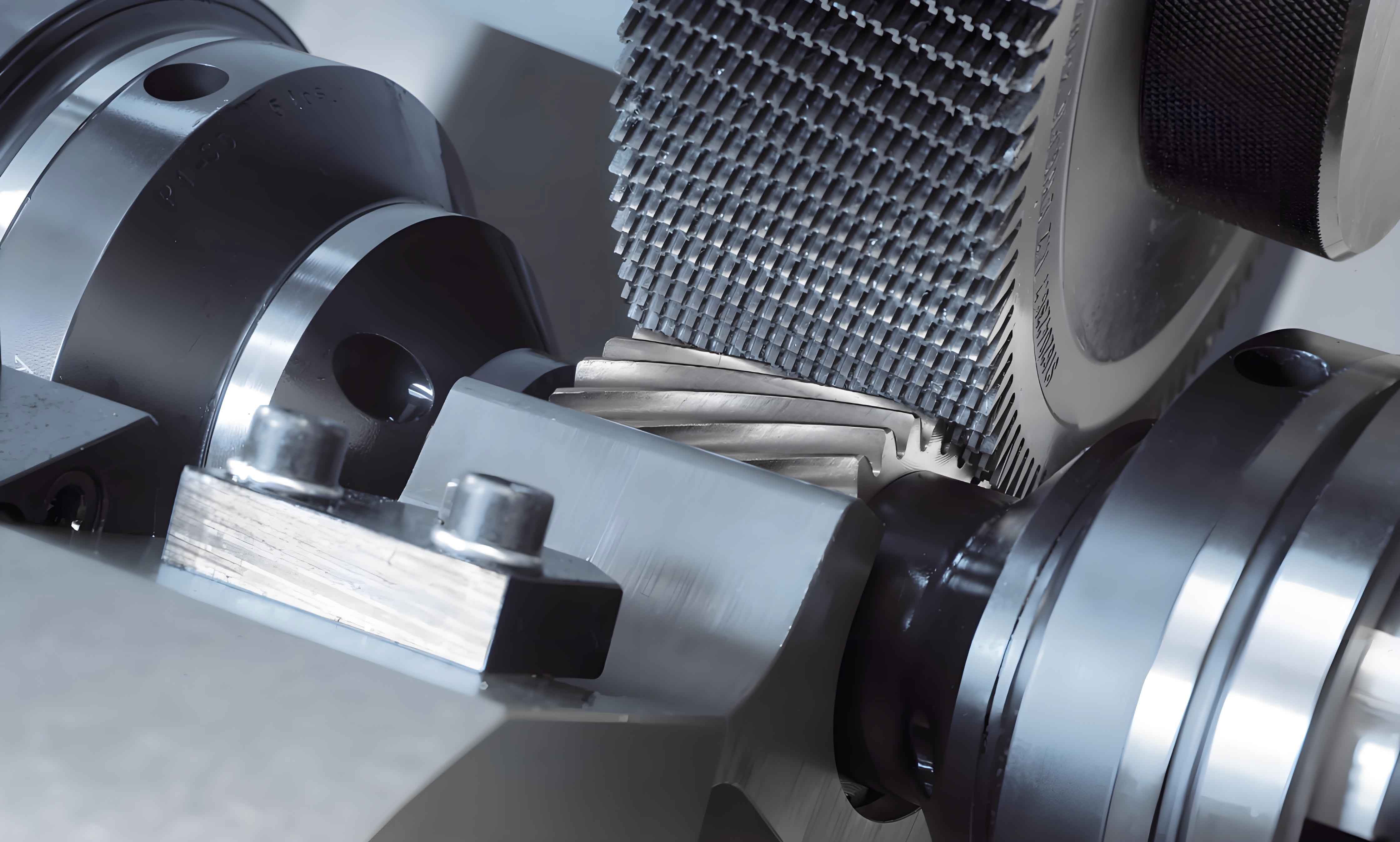
Gear shaving is a critical finishing process for enhancing the accuracy and surface quality of gears. However, the persistent issue of concave errors (mid-profile depression) near the pitch circle detrimentally impacts transmission performance, inducing vibration, noise, and reduced service life. This phenomenon remains a significant global challenge in gear manufacturing. We explore the influence of meshing contact characteristics on concave-error formation during gear shaving, leveraging elastoplastic theory and Loaded Tooth Contact Analysis (LTCA). A comprehensive mechanical model is developed to analyze contact stress, deformation distribution, and plastic accumulation under varying loads. Finite Element Method (FEM) simulations and experimental validations corroborate the theoretical framework, revealing the nonlinear relationship between load, plastic zones, and error manifestation.
1. Mathematical Modeling of Gear Shaving Meshing
Gear shaving involves discontinuous spatial meshing between crossed axes. We simplify it as an equivalent helical-spur gear pair meshing under crossed axes. Key parameters for the shaving cutter and workpiece gear are:
| Parameter | Shaving Cutter | Work Gear |
|---|---|---|
| Number of Teeth | 43 | 12 |
| Module (mm) | 5.35 | 5.35 |
| Pressure Angle | 20° | 20° |
| Helix Angle | 11° | – |
| Material | W18Cr4V | 20CrMnTi |
| Young’s Modulus (MPa) | 218,000 | 206,000 |
| Poisson’s Ratio | 0.3 | 0.25 |
| Yield Strength (MPa) | – | ≥ 835 |
Establish coordinate systems: Fixed frame \( S(O-xyz) \), cutter frame \( S_1(O_1-x_1y_1z_1) \), and gear frame \( S_2(O_2-x_2y_2z_2) \). The meshing equation governing the contact point trajectory is derived from spatial gearing theory:
$$ \omega_2 \cos \phi_1 \left[ -(z_1 + l_1) \sin \Sigma n_{x_1}^{(1)} – \left( a \cos \Sigma + \frac{v_{02}}{\omega_2} \sin \Sigma \right) n_{y_1}^{(1)} + x_1 n_{z_1}^{(1)} \sin \Sigma \right] + \omega_1 \sin \phi_1 \left[ -(z_1 + l_1) n_{y_1}^{(1)} \sin \Sigma – \left( a \cos \Sigma + \frac{v_{02}}{\omega_2} \sin \Sigma \right) n_{y_1}^{(1)} + y_1 n_{z_1}^{(1)} \sin \Sigma \right] + (\omega_1 – \omega_2 \cos \Sigma)( -x_1 n_{y_1}^{(1)} + y_1 n_{x_1}^{(1)} ) – (a \omega_2 \sin \Sigma + v_{01} – v_{02} \cos \Sigma) n_{z_1}^{(1)} = 0 $$
where \( \phi_1 \) is cutter rotation angle, \( \Sigma \) is shaft angle, \( a \) is center distance, \( \omega_1, v_{01}, \omega_2, v_{02} \) are angular and axial velocities, \( n^{(1)} \) is the normal vector component in \( S_1 \). This equation contains two independent parameters (\( \omega_1, v_{02} \)), implying discrete contact points. Transition to line contact requires satisfying the degeneration condition:
$$ \frac{i_{21}}{i”} = \frac{p_1}{\cos \Sigma} $$
where \( i_{21} = z_1 / z_2 \) is gear ratio, \( i” \) is differential ratio, \( p_1 \) is cutter spiral parameter. This ensures force equilibrium and smoother transmission during gear shaving.
2. Loaded Tooth Contact Analysis (LTCA) and Contact Characteristics
Gear shaving is an elastic-plastic extrusion-cutting process under radial force \( F_r \). We analyze the right flank of the work gear. LTCA identifies meshing states (2-, 3-, or 4-point contact) and calculates normal force \( F_n \), contact stress \( \sigma_H \), and elastic deformation \( \delta_e \) per meshing phase. Force equilibrium equations and compatibility conditions (e.g., for 4-point contact) are solved:
$$ \frac{F_1}{b_1} + \frac{F_2}{b_2} = \frac{F_3}{b_3} + \frac{F_4}{b_4} $$
Elastic deformation \( \delta_e \) and Hertzian contact stress \( \sigma_H \) are:
$$ \delta_e = \frac{4(1 – \nu^2)P}{\pi E} \left( \ln 2 + \ln \frac{L}{b} \right) $$
$$ \sigma_H = Z_H Z_E Z_\epsilon Z_\beta \sqrt{ \frac{F_n \cos \alpha_t \cos \beta}{d_1 b} \cdot \frac{u + 1}{u} } K_H $$
where \( Z_H, Z_E, Z_\epsilon, Z_\beta \) are AGMA factors, \( K_H = K_A K_V K_{H\alpha} K_{H\beta} \) is load factor, \( b \) is semi-major axis of contact ellipse. Contact characteristics under radial forces (700 N, 1100 N, 1500 N, 2000 N) are calculated:
| Radial Force \( F_r \) (N) | Max Contact Stress \( \sigma_{H_{max}} \) (MPa) | Max Elastic Deformation \( \delta_{e_{max}} \) (μm) | Critical Meshing Zone |
|---|---|---|---|
| 700 | 760 | 8.2 | DE (3-point) |
| 1100 | 980 | 12.1 | CD (2-point), DE (3-point) |
| 1500 | 1180 | 16.7 | CD, DE, EF (4-point) |
| 2000 | 1420 | 22.5 | CD, DE, EF, FG (3-point) |
Key observations from LTCA:
- Stress/deformation increase nonlinearly with \( F_r \).
- Dedendum experiences higher stress/deformation than addendum (\( \sigma_{root} / \sigma_{tip} \approx 1.4 \)).
- Peak stress occurs in the pitch-circle (PC) adjacent DE zone (3-point contact) and CD zone (2-point contact).
- DE zone exhibits force imbalance due to asymmetric meshing, making it prone to plastic flow.
3. Elastoplastic Deformation and Concave-Error Mechanism
Plastic deformation initiates when contact stress exceeds the material yield strength (\( \sigma_H \geq \sigma_s = 835 \) MPa). Using contact stress as the demarcation criterion, we partition the tooth profile into zones:
$$ \begin{cases}
\text{Elastic Zone:} & \sigma_H < \sigma_s \\
\text{Elastoplastic Zone:} & \sigma_s \leq \sigma_H < 1.5\sigma_s \\
\text{Plastic Zone:} & \sigma_H \geq 1.5\sigma_s
\end{cases} $$
The evolution of plastic zones under increasing \( F_r \) is summarized below:
| Radial Force \( F_r \) (N) | Plastic Zone (\( \sigma_H \geq 1252.5 \) MPa) | Elastoplastic Zone (\( 835 \leq \sigma_H < 1252.5 \) MPa) |
|---|---|---|
| 700 | None | Localized at DE |
| 1100 | DE (partial) | CD, DE, EF |
| 1500 | CD, DE | CD, DE, EF, FG |
| 2000 | CD, DE, EF | AB, CD, DE, EF, FG |
The concave-error formation mechanism is:
- Stress Concentration: Peak stresses occur at PC-adjacent DE (3-point) and CD (2-point) zones during gear shaving.
- Plastic Accumulation: Low-cycle fatigue in gear shaving causes irreversible plastic strain accumulation in these zones.
- Error Replication: Plastic deformation replicates as geometric error on successive work gear teeth.
- Mid-Profile Depression: Cumulative plastic flow manifests as concave error (0.01–0.03 mm) near the pitch circle.
4. Finite Element Validation
A 3D FEM model with five teeth per gear avoids edge effects. Simulations under identical \( F_r \) values yield contact stress distributions and plastic zones. Comparisons with LTCA:
| Radial Force \( F_r \) (N) | Max \( \sigma_H \) LTCA (MPa) | Max \( \sigma_H \) FEM (MPa) | Error (%) | Plastic Zone Discrepancy |
|---|---|---|---|---|
| 700 | 760 | 698 | 9.77 | FEM > LTCA at DE |
| 1100 | 980 | 856 | 12.63 | FEM extends to EF |
| 1500 | 1180 | 1002 | 15.05 | FEM: Larger CD, DE zones |
| 2000 | 1420 | 1147 | 19.18 | FEM: Includes AB, FG |
FEM confirms:
- Nonlinear plastic zone expansion with \( F_r \).
- Stress peaks near the pitch circle during gear shaving.
- Larger plastic zones in FEM due to dynamic effects and transient meshing transitions.
- Consistent plastic accumulation in DE/CD zones validates the concave-error mechanism.
5. Experimental Verification
Gear shaving tests on a YW4232 machine used radial feeds correlating to \( F_r \). Post-shaving profile errors were measured using a GM3040a gear tester:
| Radial Force \( F_r \) (N) | Concave Error Depth (mm) | Location | Profile Irregularities |
|---|---|---|---|
| 700 | 0.012 | PC ± 5° | Minor fluctuations |
| 1100 | 0.021 | PC ± 8° | Distinct depression |
| 1500 | 0.028 | PC ± 10° | Pronounced concave |
| 2000 | 0.025 | PC ± 12° | Oscillation, over-cutting |
Results confirm:
- Concave errors appear near the pitch circle across all loads in gear shaving.
- Error depth increases with \( F_r \) (700 N → 1500 N), validating nonlinear plastic accumulation.
- Optimal \( F_r \) exists (e.g., 1500 N); excessive force (2000 N) causes instability and over-cutting.
- Experimental profiles align with LTCA/FEM stress/deformation trends, corroborating the plastic-flow-driven mechanism.
6. Conclusion
We establish a mechanistic model for concave-error formation in gear shaving via LTCA, elastoplastic theory, FEM, and experimentation. Key findings are:
- Meshing degeneracy \( \frac{i_{21}}{i”} = \frac{p_1}{\cos \Sigma} \) enables line contact, improving force distribution.
- Peak contact stresses occur in pitch-circle-adjacent 3-point (DE) and 2-point (CD) zones, with dedendum regions experiencing 40% higher stress.
- Plastic zones expand nonlinearly with radial force:
- \( F_r = 700 \text{N} \): Elastoplastic zone at DE.
- \( F_r = 1500 \text{N} \): Plastic zones dominate CD/DE/EF.
- Concave errors arise from low-cycle accumulation of plastic strain in high-stress zones during gear shaving, replicated as mid-profile depression.
- FEM/experimental validation confirms:
- FEM shows larger plastic zones (dynamic effects), with max error < 20%.
- Optimal \( F_r \) minimizes concave error; excessive force induces instability.
This work elucidates the role of contact mechanics and plastic flow in gear shaving defects, providing a foundation for process optimization to suppress concave errors.