
In the field of mechanical engineering, the finite element method is a widely used simulation technique for analyzing the dynamic performance of gear systems. For high-speed spur gears, particularly those employed in aerospace applications such as aero-engines, the accurate discretization of the tooth surface mesh is critical. These spur gears operate under extreme conditions—high rotational speeds, heavy loads, and minimal weight—leading to highly nonlinear and transient behaviors during service. Traditional finite element mesh generation methods often fail to account for the effects of high tangential velocities and varying curvature radii on the tooth surface, resulting in simulation inaccuracies. In this paper, I propose a novel method for determining the optimal finite element mesh size for the tooth surface of high-speed spur gears. This method adapts to changes in rolling-sliding velocities and curvature radii during gear meshing, ensuring simulation errors remain below 10%. The approach is based on simplifying the tooth contact to a cylindrical roller model and analyzing slip energy losses under different conditions. By establishing a relationship between mesh size, curvature radius, and tangential velocity, I provide a practical guideline for mesh discretization that enhances the reliability of finite element simulations for spur gears.
The importance of spur gears in power transmission cannot be overstated, especially in high-speed applications like aircraft engines. These spur gears are subject to severe mechanical stresses and thermal effects, making their design and analysis paramount. Finite element analysis (FEA) has become a cornerstone for studying gear dynamics, but the accuracy of FEA results heavily depends on the mesh quality. The tooth surface of spur gears is a complex curved geometry, and its discretization into finite elements must capture the nuances of contact mechanics. However, existing mesh generation techniques often overlook the influence of high linear speeds, which induce centrifugal forces in the mesh elements, leading to artificial vibrations and errors in contact simulation. This paper addresses this gap by introducing a method that correlates mesh size with operational parameters such as tangential velocity and curvature radius. The goal is to achieve a balance between computational efficiency and simulation precision, enabling more accurate predictions of contact stresses and wear in spur gears.
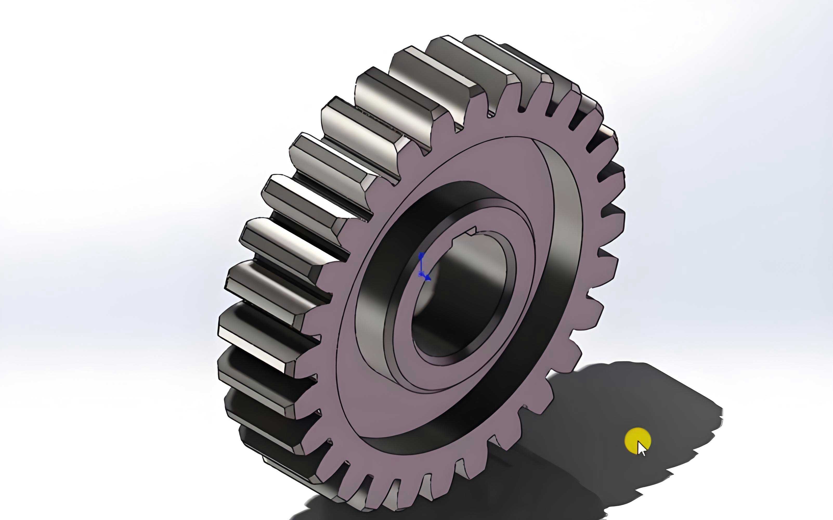
The fundamental challenge in meshing spur gears lies in the nature of their tooth profiles. Spur gears feature involute teeth, which are essentially smooth curves composed of arcs with varying curvature radii. During meshing, the contact between two spur gear teeth can be approximated as the contact between two cylindrical surfaces. This simplification is supported by experimental studies, such as those by Weck et al., which show that under similar working conditions, gear tooth contact can be modeled as line contact between rollers. In this context, the radii of the rollers correspond to the curvature radii of the spur gear teeth at the contact point, the rotational speeds reflect the tangential velocities, and the applied load represents the normal force between the teeth. By using this cylindrical roller model, I can systematically investigate the effects of mesh size on simulation accuracy, focusing on slip energy loss as a metric. Slip energy loss occurs due to friction between sliding surfaces and is given by the theoretical formula: $$E = f \times F \times V_t \times t$$ where \(f\) is the friction coefficient, \(F\) is the normal load, \(V_t\) is the relative sliding velocity, and \(t\) is time. For spur gears, this energy loss is a key indicator of contact conditions and can be used to validate finite element models.
To apply the cylindrical roller model effectively, it is essential to derive the geometric and kinematic parameters of spur gear meshing. Consider a pair of spur gears in mesh, where the driving gear rotates and drives the driven gear. The involute profile of spur gears ensures that the line of action is straight, and the contact point moves along this line during meshing. The curvature radius at any point on the tooth surface of spur gears is equal to the length of the generatrix of the involute. For the driving gear, the curvature radius \(\rho_1\) at a contact point is given by: $$\rho_1 = \sqrt{r_k^2 – r_{b1}^2}$$ where \(r_k\) is the radius to the contact point on the driving gear, and \(r_{b1}\) is the base circle radius of the driving gear. Similarly, for the driven gear in spur gears, the curvature radius \(\rho_2\) is: $$\rho_2 = (r_1 + r_2) \sin \alpha – \sqrt{r_k^2 – r_{b1}^2}$$ where \(r_1\) and \(r_2\) are the pitch circle radii of the driving and driven spur gears, respectively, and \(\alpha\) is the pressure angle. These equations allow me to calculate the range of curvature radii encountered during meshing of spur gears, which is crucial for setting up the roller model.
The tangential velocity on the tooth surface of spur gears is another vital parameter. For the driving gear, the tangential velocity \(V_{1t}\) at a contact point is derived from the rotational speed and curvature radius: $$V_{1t} = \frac{2\pi n_1 \rho_1}{60 \times 1000}$$ where \(n_1\) is the rotational speed in rpm, and \(\rho_1\) is in mm. For the driven gear in spur gears, the tangential velocity \(V_{2t}\) is: $$V_{2t} = \frac{2\pi n_2 \rho_2}{60 \times 1000}$$ where \(n_2\) is the driven gear speed. The relative sliding velocity \(V_t\) between the tooth surfaces of spur gears is then: $$V_t = V_{1t} – V_{2t}$$ This relative velocity varies along the line of action, reaching zero at the pitch point and maximum at the start or end of engagement. Understanding this variation is key to simulating the contact conditions in spur gears accurately.
Additionally, the normal load on the tooth surface of spur gears must be determined. For spur gears, the force analysis involves decomposing the normal force into tangential and radial components. The nominal normal force \(F_n\) can be expressed as: $$F_n = \frac{9550 P}{n_2 r_{b2}}$$ where \(P\) is the power transmitted in kW, \(n_2\) is the driven gear speed, and \(r_{b2}\) is the base circle radius of the driven gear. This load, along with the curvature radii and velocities, forms the basis for the boundary conditions in the cylindrical roller model. In high-speed spur gears, these parameters can span wide ranges, as seen in aero-engine applications. For instance, based on calculations for a typical aero-engine gearbox, the curvature radii for spur gears might range from 15 mm to 37.6 mm, tangential velocities from 6.7 m/s to 71.8 m/s, relative sliding velocities up to 28.6 m/s, and loads from 1902 N to 4739 N. These ranges inform the selection of parameters for the finite element simulations.
With these theoretical foundations, I proceed to the mesh discretization method. The core idea is to use a cylindrical roller contact finite element model to emulate the tooth contact of spur gears. By varying the mesh size on the contact surface and analyzing the slip energy loss under different tangential velocities, I can establish a correlation between mesh size and curvature radius that minimizes simulation error. The cylindrical roller model consists of two rollers with radii corresponding to the curvature radii of spur gear teeth. The rollers are assigned rotational speeds to match the tangential velocities, and a normal load is applied to represent the gear force. The contact between the rollers is defined with a friction coefficient, typically 0.01 to 0.02 for well-lubricated spur gears. I then simulate the contact over a short duration, such as 0.001 seconds, which approximates the meshing time for high-speed spur gears. The slip energy loss from the simulation is compared to the theoretical value calculated using the formula above. The error percentage is used as a metric to assess the accuracy of the mesh discretization for spur gears.
To cover the operational range of high-speed spur gears, I set up multiple finite element models with different parameters. The table below summarizes the models used in this study, focusing on variations in tangential velocity and mesh size relative to curvature radius.
| Model ID | Normal Load (N) | Roller Length (mm) | Roller Radii (mm) | Tangential Velocities (m/s) | Mesh Size 1 | Mesh Size 2 | Mesh Size 3 | Mesh Size 4 |
|---|---|---|---|---|---|---|---|---|
| 1 | 3000 | 15 | 15, 20 | 25, 5 | R/20 | R/30 | R/40 | R/50 |
| 2 | 3000 | 15 | 15, 20 | 40, 20 | R/50 | R/60 | R/70 | R/80 |
| 3 | 3000 | 15 | 15, 20 | 55, 35 | R/90 | R/100 | R/110 | R/120 |
| 4 | 3000 | 15 | 15, 20 | 70, 50 | R/110 | R/120 | R/130 | R/140 |
In this table, R denotes the curvature radius of the rollers, which corresponds to the tooth surface curvature of spur gears. The mesh size is expressed as a fraction of R, such as R/20, meaning the element size on the contact surface is one-twentieth of the curvature radius. For each model, I keep the relative sliding velocity constant at 20 m/s to isolate the effect of tangential velocity. The friction coefficient is fixed at 0.01, representative of spur gears under ideal lubrication. The finite element simulations are performed using ANSYS with the LS-DYNA solver, and the slip energy loss is extracted over time intervals up to 0.001 seconds. The error between simulated and theoretical slip energy is calculated, and a threshold of less than 10% error is set for acceptable accuracy in spur gear simulations.
The results from these simulations reveal important trends. As the mesh is refined (i.e., smaller element sizes), the percentage error in slip energy decreases. However, the error also depends on the maximum tangential velocity on the contact surface. For a given mesh refinement level, higher tangential velocities lead to larger errors. This is due to the increased centrifugal effects and numerical instabilities in the finite element model at high speeds. For example, in Model 1 with a maximum tangential velocity of 25 m/s, mesh sizes of R/40 to R/50 yield errors below 10%. In Model 2 with 40 m/s, mesh sizes of R/70 to R/80 are required. For Model 3 at 55 m/s, mesh refinement must reach at least R/110, and for Model 4 at 70 m/s, R/140 is necessary. These findings are synthesized into a practical guideline for mesh discretization of spur gears, as shown in the following table.
| Maximum Tooth Surface Tangential Velocity (m/s) | Tooth Surface Mesh Refinement |
|---|---|
| 0–25 | r/40 |
| 25–40 | r/70 |
| 40–55 | r/110 |
| 55–70 | r/140 |
Here, r represents the minimum curvature radius on the tooth surface of spur gears, typically at the root of the tooth. This table provides a straightforward rule for selecting mesh sizes based on operational speed, ensuring that finite element simulations for spur gears remain accurate within the desired error margin. It balances computational cost (since finer meshes increase simulation time) and precision, which is crucial for engineering applications involving spur gears.
To validate this method, I apply it to a real-world case study: a pair of spur gears from an aero-engine gearbox. The spur gears have the following parameters: driving gear with 57 teeth, driven gear with 43 teeth, module of 2.5 mm, face width of 12 mm, and pressure angle of 25°. Using the derived formulas, I calculate the minimum curvature radii as 24.7 mm for the driving gear and 17.2 mm for the driven gear. For four different operating conditions with varying speeds and powers, I determine the maximum tangential velocities and corresponding mesh sizes based on the guideline table. The details are summarized below.
| Operating Condition | Output Power (kW) | Driving Gear Speed (rpm) | Driven Gear Speed (rpm) | Max Tangential Velocity (m/s) | Mesh Refinement | Driving Gear Mesh Size (mm) | Driven Gear Mesh Size (mm) |
|---|---|---|---|---|---|---|---|
| 1 | 145 | 14970 | 19844 | 58.4 | r/140 | 0.176 | 0.123 |
| 2 | 145 | 11392 | 15101 | 44.5 | r/110 | 0.225 | 0.156 |
| 3 | 145 | 7773 | 10304 | 30.3 | r/70 | 0.353 | 0.246 |
| 4 | 145 | 5093 | 6751 | 19.9 | r/40 | 0.618 | 0.430 |
For each condition, I create a finite element model of the spur gear pair using hexahedral elements on the tooth surfaces, with node spacing equal to the calculated mesh sizes. The models include rotational speeds, torques, and contact definitions, and are solved in LS-DYNA. I extract the contact stresses at the pitch point during stable meshing. The results show elliptical stress distributions typical of spur gear contact, with maximum contact stresses ranging from 545.2 MPa to 666.5 MPa across conditions. Comparing these simulation values to theoretical Hertzian contact stresses (calculated with appropriate dynamic factors per ISO standards), the errors are all below 10%: 9.1% for Condition 1, 8.7% for Condition 2, 9.9% for Condition 3, and 5.6% for Condition 4. This demonstrates the effectiveness of the proposed mesh discretization method for spur gears.
To further illustrate the importance of mesh size selection, I conduct a sensitivity analysis for Condition 1. Using a coarser mesh (0.35 mm element size) and a finer mesh (0.095 mm) than recommended, I simulate the same spur gear pair. The coarse mesh yields a maximum contact stress of 340.5 MPa, with a 39% error relative to theory, indicating poor accuracy. The fine mesh gives 541.3 MPa, with a 3% error, showing improved precision but at a significantly higher computational cost. The recommended mesh size (0.176 mm for the driving gear) strikes a balance, achieving a 9.1% error with reasonable simulation time. This underscores that arbitrary mesh refinement is not optimal; instead, a tailored approach based on tangential velocity and curvature radius is essential for spur gears.
The proposed method has several advantages for the analysis of spur gears. First, it provides a systematic way to determine mesh size that adapts to the dynamic conditions of high-speed operation. Second, it leverages a simplified cylindrical roller model to reduce computational complexity while maintaining accuracy. Third, the guideline table allows engineers to quickly select appropriate mesh parameters for spur gears without extensive trial-and-error. This is particularly valuable in industries like aerospace, where spur gears are critical components and simulation reliability is paramount. Moreover, the method can be extended to other gear types, such as helical or bevel gears, by adapting the curvature and velocity calculations. However, for spur gears, the involute profile and straight-line contact simplify the analysis, making this approach directly applicable.
In conclusion, I have developed a precise finite element mesh discretization method for the tooth surface of high-speed spur gears. By analyzing the relationship between mesh size, curvature radius, and tangential velocity through cylindrical roller simulations, I established a practical criterion: for maximum tangential velocities of 0–25 m/s, mesh size should be r/40; for 25–40 m/s, r/70; for 40–55 m/s, r/110; and for 55–70 m/s, r/140, where r is the minimum curvature radius on the tooth surface of spur gears. Validation with aero-engine spur gears confirms that this method keeps simulation errors below 10%, ensuring accurate predictions of contact stresses and performance. Future work could explore the effects of temperature, lubrication variations, and surface roughness on mesh discretization for spur gears. Additionally, integrating this method into automated finite element preprocessing tools would streamline the design process for spur gears in high-speed applications. Ultimately, this contribution enhances the reliability of finite element analysis for spur gears, supporting the development of more efficient and durable transmission systems.
The implications of this research are significant for the design and optimization of spur gears in demanding environments. As industries push for higher speeds and lighter weights, the need for accurate simulation tools grows. The method presented here addresses a key challenge in finite element modeling of spur gears, paving the way for more robust analyses. By adhering to the mesh refinement guidelines, engineers can confidently simulate spur gear behavior, reduce prototyping costs, and improve product reliability. In summary, this paper offers a novel, evidence-based approach to mesh discretization that advances the state-of-the-art in gear dynamics for spur gears.