Taking the modeling process of small wheel as an example, this paper introduces the modeling process of hypoid gear with small number of teeth and large reduction ratio in UG. The modeling process of large wheel is similar to that of small wheel.
After obtaining the three-dimensional tooth surface points of hypoid gear pair with small number of teeth and large reduction ratio, save the obtained three-dimensional coordinate points as dat format that can be recognized by UG, then import the obtained tooth surface points into UG, and establish the three-dimensional solid model of hypoid gear with small number of teeth and large reduction ratio through commands such as ruled, stitching, transformation and trimming.
Taking the hypoid gear with small number of teeth and large reduction ratio of 4:41 teeth as an example, in order to avoid undercutting of the gear or sharpening of the tooth top, the midpoint helix angle of the small wheel is taken as a larger value of 58.358 °. At the same time, in order to balance the strength of the large and small wheel, the height and tangential displacement are comprehensively considered. 4: The modeling process of large and small wheels with 41 tooth ratio is described as follows. This paper mainly studies the three-dimensional modeling and machining of the small wheel of hypoid gear with small number of teeth. In order to ensure the integrity of the graphics and the clarity of the observation of the tooth profile of the small wheel, different proportions are adopted for the screenshots of the large and small wheel.
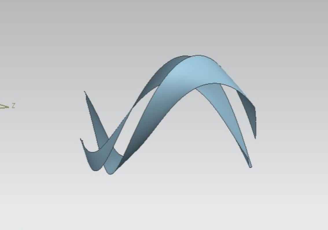
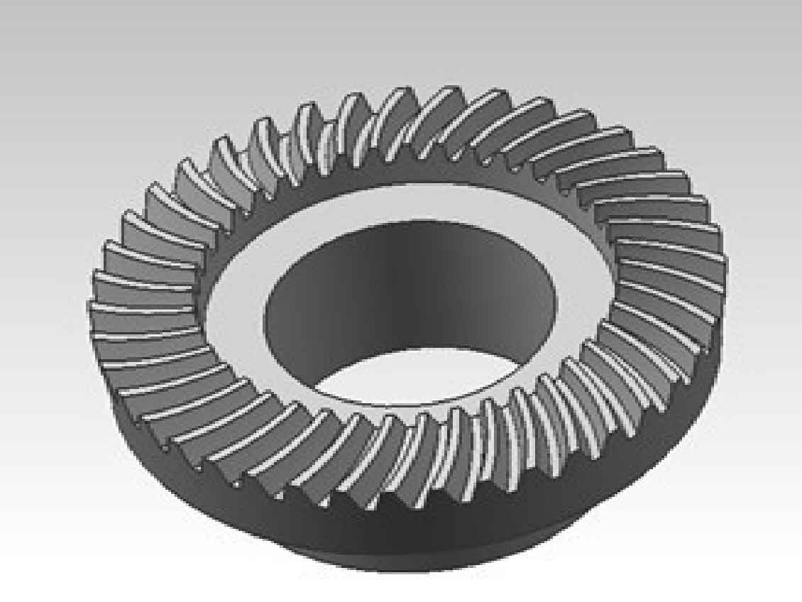
Modeling process of hypoid gear with small number of teeth and large reduction ratio: firstly, draw the plan of small wheel blank in UG software according to the calculated geometric parameters of small wheel, and use the rotation command in UG to establish the three-dimensional graphics of small wheel blank. Import the calculated three-dimensional data points of the pinion tooth surface into the UG three-dimensional software to generate the convex and concave surfaces of the pinion tooth surface respectively, as shown in Fig. 1 and Fig. 2. Establish the tooth root surface of the small wheel by using the ruled grain command, and sew the edges on the tooth surface of the hypoid gear pinion after appropriate tangent extension. According to the tooth height of the big end and the tooth height of the small end of the large hypoid gear, intersect the sewn tooth groove sheet with the wheel blank, and adjust the position between the tooth groove and the wheel blank, Using the trim body command in UG software, a tooth groove of the small wheel can be cut on the wheel blank, and the cut tooth groove can be patterned in a circular array to obtain the three-dimensional model of the small wheel. The modeling process is shown in Figure 1-3.
After importing the surface points of hypoid gear large teeth calculated by Mtalab software into UG, the process of establishing the three-dimensional model of hypoid gear wheel is the same, and the three-dimensional model of large wheel can be obtained, as shown in Figure 4-6.
It can be seen from the figure that the large and small tooth shapes of 4:41 hypoid gear are intact, the tooth roots are continuous and there is no undercutting; The thickness distribution of tooth tip is appropriate without sharpening.


