
In marine valve remote control systems, the actuators that drive butterfly valves and ball valves are normally grouped into electric, pneumatic, hydraulic and electro-hydraulic families. Each of them carries a distinct set of compromises, and the selection is rarely driven by a single criterion. An electric actuator offers a wide choice of communication protocols and a fast response, yet once a single-acting (spring-return) function is required, the gearbox becomes complicated, the reduction ratio grows, and the overall envelope expands considerably. In submerged installations an electric actuator simply cannot be applied. A pneumatic actuator draws its energy from compressed air, which keeps the structure simple, but because air is compressible and the supply pressure is generally limited to the range of 0.2–0.8 MPa, the achievable output torque is bounded; the largest units available on the market reach roughly 4 000 N·m only at the cost of a very large body, and both motion stability and response speed suffer. A helical hydraulic actuator uses a two-stage involute helical pair, which demands complex manufacturing processes, high machining accuracy and a high price; when it must also be single-acting, the axial dimension becomes long and the installation envelope becomes demanding. An electro-hydraulic actuator combines the advantages of the electric and hydraulic types and can position a valve quickly and stably, but every unit carries its own power pack, which raises the cost substantially.
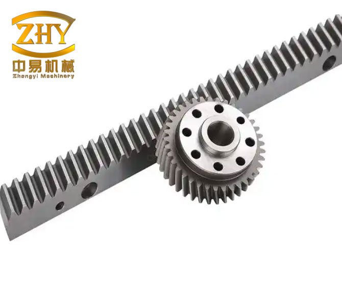
Weighing all of these trade-offs, I chose a different architecture for the present work: a rack and pinion gear type single-acting hydraulic actuator that stores energy in a disc spring stack. When the hydraulic power source is lost, the disc spring releases its stored potential energy and automatically closes a butterfly valve that was standing in the fully open position. Compared with helical hydraulic actuators, the rack and pinion gear concept is much easier to manufacture, requires lower machining accuracy and costs less. Compared with actuators that use helical compression springs for energy storage, it is smaller and lighter. Furthermore, the single-acting rack and pinion gear layout is long in the axial direction but low in width and height, so it can be mounted along the pipe axis while occupying very little vertical space, which saves installation envelope in marine valve remote control systems. This is precisely why single-acting rack and pinion gear actuators are widely used in ventilation systems on board ships.
| Actuator type | Power source | Typical torque capability | Single-acting feasibility | Relative cost | Submerged service |
|---|---|---|---|---|---|
| Electric | Electric motor | Wide range | Poor – complex gearbox, large envelope | Medium | Not suitable |
| Pneumatic | Compressed air 0.2–0.8 MPa | Up to about 4 000 N·m | Good, but bulky | Low | Limited |
| Helical hydraulic | Hydraulic oil | High | Good, but axially long | High | Good |
| Electro-hydraulic | Integrated power pack | High | Good | Very high | Good |
| Single-acting rack and pinion gear hydraulic | Central hydraulic supply | High, compact | Excellent – disc spring return | Low | Good |
Working Principle and Structural Architecture
The operating principle of the actuator I developed can be described as follows. A motor drives a gear pump at high speed and delivers hydraulic oil through a dedicated circuit into the piston sealing chamber of the actuator. The pressurised oil pushes the piston towards the disc spring chamber while simultaneously compressing the disc spring stack. The movement continues until a contact switch inside the valve position indicator is triggered, which sends a “valve fully open” signal to the control system and stops the motor. When the control system issues a closing command, the two-position two-way solenoid valve is de-energised and returns to its normally open working position. The compressed disc spring then releases its stored potential energy, displacing the oil in the piston chamber back through the circuit to the reservoir and driving the piston in the opposite direction until the closed position is reached.
The structural principle of the unit is built around a machined body that contains a cross-shaped internal bore arrangement. This cross bore accommodates the rack and pinion gear pair: the pinion shaft runs in one direction and the toothed rack runs perpendicular to it. Two cylinder barrels are threaded into the body. The piston, the cylinder barrel, the end-stop bolts and the associated seals together enclose the sealed working chamber, while the disc spring stack and the single-acting cylinder barrel form the spring chamber that stores the elastic potential energy. The piston carries a wear ring, a U-cup and a glyd ring, and it slides freely inside the cylinder barrel; the end-stop bolts at both ends limit the travel of the rack. When high-pressure oil enters the working chamber through the ferrule connector, it pushes the rack in one direction, rotates the pinion shaft, and compresses the disc spring stack. If the external power source is suddenly lost while the valve is open, the disc spring, which has been held in the compressed state, releases its energy, drives the rack back in the opposite direction, rotates the pinion shaft in the closing sense, and shuts the valve.
| Item | Component | Function |
|---|---|---|
| 1 | Fastening bolt | Clamps the cylinder end cover to the barrel |
| 2 | Cylinder end cover | Closes the spring chamber, centres the guide rod |
| 3 | Guide rod end cover | Supports and centres the disc spring guide rod |
| 4 | Open end-stop bolt | Limits rack travel at the fully open position |
| 5 | Disc spring guide rod | Prevents buckling and lateral displacement of the stack |
| 6 | Disc spring stack | Stores elastic potential energy for fail-safe return |
| 7 | Cylinder barrel | Forms the hydraulic working chamber |
| 8 | Single-acting piston | Converts hydraulic pressure into linear thrust |
| 9 | Toothed rack | Converts linear motion into rotation of the rack and pinion gear pair |
| 10 | Body | Provides the cross bore and the structural frame |
| 11 | Pinion shaft | Delivers the output torque to the valve stem |
| 12 | Opposite cylinder barrel | Guides the rack on the non-pressurised side |
| 13 | Ferrule connector | Interfaces the hydraulic supply line |
| 14 | Close end-stop bolt | Limits rack travel at the fully closed position |
| 15 | Thin nut | Locks the end-stop setting |
| 16 | Wear ring | Prevents metal-to-metal contact of piston and bore |
| 17 | Glyd ring | Provides low-friction dynamic sealing |
| 18 | U-cup seal | Primary pressure sealing element |
| 19 | O-ring | Static sealing of threaded joints |
| 20 | Cap nut | Retains and protects the shaft end |
Mechanical Design of the Rack and Pinion Gear Pair
The starting point of the sizing exercise was the requirement that the actuator deliver an output torque of 160 N·m at the 0° initial position, that is, with the valve fully closed and the disc spring only lightly loaded. The rack and pinion gear pair is the only torque-transmitting element in the chain, so the module and the number of teeth follow directly from the torque requirement and the allowable bending stress at the tooth root. Because the pinion must resist both shear and bending and must also resist wear at the tooth flank, I selected plain carbon steel 45 with a QPQ salt-bath treatment to raise surface hardness and abrasion resistance, while the rack was made from 40Cr steel with quenching and tempering. The mechanical properties of the two materials are listed in Table 3.
| Part | Material | Tensile strength σb (MPa) | Yield strength σs (MPa) | Heat treatment |
|---|---|---|---|---|
| Pinion | 45 | 650 | 360 | QPQ salt-bath nitriding |
| Rack | 40Cr | 700 | 500 | Quenching and tempering |
Because the rack and pinion gear pair sits in a relatively enclosed space and is permanently immersed in grease, the governing failure mode is tooth-root bending rather than flank scuffing. I therefore verified the module against the bending strength criterion:
$$ m \ge \sqrt[3]{\frac{2KT’}{\phi_d Z_1^{\,2}}\left(\frac{Y_{Fa}Y_{Sa}}{[\sigma_F]}\right)} = 2.97\ \text{mm} $$
where K is the load factor, T′ is the design output torque in N·m, φd is the face-width factor, d is the reference diameter in mm, [σF] is the allowable bending fatigue strength in MPa, YFa is the tooth form factor and YSa is the stress correction factor. The calculation returned a minimum module of 2.97 mm, so I rounded upwards to a standard value and fixed the final geometry at a module of 3 mm with 18 pinion teeth. The complete gear data set is summarised in Table 4.
| Parameter | Symbol | Value |
|---|---|---|
| Module | m | 3 mm |
| Number of pinion teeth | Z | 18 |
| Reference (pitch) diameter | d = mZ | 54 mm |
| Reference radius | R = mZ/2 | 27 mm |
| Face width | b | 32 mm |
| Pressure angle | α | 20° |
| Rack linear travel per 90° rotation | S | 42.39 mm |
The lever arm of the rack and pinion gear pair, which converts the rack thrust into output torque, follows directly from the reference radius:
$$ R = \frac{mZ}{2} = 0.027\ \text{m} $$
so the rack thrust required to produce the specified initial torque of 160 N·m is:
$$ F_1 = \frac{T_1}{R} = \frac{160}{0.027} = 5\,926\ \text{N} $$
where T1 is the torque at the 0° initial position and F1 is the corresponding rack thrust.
Disc Spring Selection and Energy Storage Calculation
The disc spring stack is the fail-safe element of the whole design, and its selection drives both the closing torque available when the power supply fails and the total axial length of the actuator. I arranged the springs in a stacked (series) configuration so that the individual deflections add up, which keeps the required number of parallel elements low while still delivering the necessary force.
Starting from the 90° stroke, the rack travel is obtained from the arc length swept by the pitch circle:
$$ S = \frac{\pi m Z \times 90^{\circ}}{360^{\circ}} = \frac{\pi \times 3 \times 18}{4} = 42.39\ \text{mm} $$
When the supply pressure is 13 MPa and the cylinder bore is 50 mm, the gross torque that the hydraulic side can generate before subtracting the spring reaction is:
$$ T’_2 = p \cdot \frac{\pi D^2}{4} \cdot \frac{mZ}{2} \cdot \eta = 586\ \text{N}\cdot\text{m} $$
in which p is the working pressure, D is the cylinder bore, and η is the mechanical efficiency of the rack and pinion gear transmission together with the piston seals. The rack thrust that corresponds to this gross torque is:
$$ F_2 = \frac{T’_2}{R} = \frac{586}{0.027} = 21\,703\ \text{N} $$
Consequently the disc spring stack, when compressed to its shortest length, must produce a force below 21 703 N so that the hydraulic side can still overcome it and hold the valve open. Guided by that constraint I selected a disc spring of nominal size 180060 with the geometry listed in Table 5, again arranged in a stacked configuration.
| Parameter | Symbol | Value |
|---|---|---|
| Outer diameter | Do | 60 mm |
| Inner diameter | di | 20.5 mm |
| Material thickness | t | 3 mm |
| Free height | H0 | 5.2 mm |
| Initial cone height | h0 | 2.2 mm |
| Cone height ratio | h0/t | 0.733 |
| Number of springs in the stack | n | 54 |
The load–deflection characteristic of this spring shows that at the fully compressed state the single spring develops approximately 12 982 N, which is far below the 21 703 N limit imposed by the hydraulic side, so the design is safe with a comfortable margin. Matching the allowable deflection per spring to the total rack travel of 42.39 mm gave a stack of 54 springs. In the actual build, the force measured with the stack at its shortest length was F′2 = 12 892 N, so the resisting torque reflected back to the pinion shaft is:
$$ T_3 = F’_2 \cdot \frac{mZ}{2} = 12\,892 \times 0.027 = 348\ \text{N}\cdot\text{m} $$
The net output torque available at 90° with a 13 MPa supply is therefore the gross hydraulic torque minus the spring reaction torque:
$$ T_2 = T’_2 – T_3 = 586 – 348 = 238\ \text{N}\cdot\text{m} $$
| Position | Hydraulic gross torque (N·m) | Disc spring reaction torque (N·m) | Net output torque (N·m) |
|---|---|---|---|
| 0° (fully closed, initial) | — | 160 (as required) | 160 |
| 90° (fully open, 13 MPa) | 586 | 348 | 238 |
Cylinder Wall Thickness Verification
The cylinder barrels are threaded into the body, and during operation they contain oil at medium pressure. For safety I verified both the wall thickness and the bottom thickness of the barrels against the yield and ultimate strength of the material. The barrels were made from steel 45 with an ultimate tensile strength of σb = 600 MPa; taking a safety factor of 5, the allowable stress becomes:
$$ \sigma_p = \frac{\sigma_b}{n} = \frac{600}{5} = 120\ \text{MPa} $$
The total wall thickness is composed of the strength-controlled minimum plus allowances for dimensional tolerance and corrosion:
$$ \delta = \delta_0 + C_1 + C_2 $$
where C1 is the outer-diameter tolerance allowance, C2 is the corrosion allowance, and δ0 is the minimum thickness required by strength. For the thin-to-medium wall regime, defined by δ/D between 0.08 and 0.3, the strength-controlled minimum is obtained from:
$$ \delta_0 \ge \frac{p_{max} D}{2.3\sigma_p – 3p_{max}} = \frac{20 \times 50}{2.3 \times 120 – 3 \times 20} = 4.6\ \text{mm} $$
where pmax = 20 MPa is the maximum pressure considered in the verification and D is the bore. The corresponding minimum wall thickness for the 50 mm bore is given in Table 7.
| Bore D (mm) | Minimum inner wall thickness (mm) |
|---|---|
| 50 | 4.6 |
Using the smallest permissible inner wall thickness, I then checked the plastic-deformation limit of the barrel:
$$ p_N \le 0.35\,\sigma_s \frac{D_1^{\,2} – D^2}{D_1^{\,2}} = 38\ \text{MPa} $$
$$ p_N \le (0.35 \sim 0.42)\,p_{rL} $$
where pN is the rated pressure, σs = 355 MPa is the yield strength of the barrel material, D1 is the outer diameter, D is the bore and prL is the fully plastic deformation pressure. The verification results are collected in Table 8.
| Bore D (mm) | Inner wall thickness (mm) | Outer diameter D1 (mm) | Verification value (MPa) | 0.35 × fully plastic (MPa) | 0.42 × fully plastic (MPa) |
|---|---|---|---|---|---|
| 50 | 5 | 60 | 38 | 23 | 27 |
The bottom of the barrel must also resist the internal pressure, and the required bottom thickness follows from:
$$ \delta_1 \ge 0.433\,D_2\sqrt{\frac{p}{\sigma_p}} = 8.8\ \text{mm} $$
with p the maximum working pressure, σp = 120 MPa the allowable stress and D2 the outer diameter of the barrel. The calculated minimum bottom thickness for the 50 mm bore is listed in Table 9.
| Bore (mm) | Minimum bottom thickness (mm) |
|---|---|
| 50 | 8.8 |
Working Volume and Displacement
The volume of oil that the power pack must deliver for one complete stroke defines the pump displacement and the size of the reservoir that serves a bank of actuators. Because the piston area is fixed by the 50 mm bore, the swept volume follows directly from the rack travel computed earlier:
$$ V_1 = \frac{\pi D^2}{4000}\,S = \frac{\pi \times 50^2}{4000} \times 42.39 = 83\ \text{mL} $$
so a single stroke from the closed to the fully open position consumes approximately 83 mL of hydraulic oil. This figure was used later to size the supply lines and to estimate the response time of the actuator bank. Table 10 gathers the kinematic and volumetric quantities of the design.
| Quantity | Symbol | Value |
|---|---|---|
| Pinion rotation, closed to open | Δθ | 90° |
| Rack travel | S | 42.39 mm |
| Cylinder bore | D | 50 mm |
| Piston area | A | 1 963.5 mm² |
| Oil volume per stroke | V1 | 83 mL |
| Rated supply pressure | p | 13 MPa |
| Proof pressure | pproof | 19.5 MPa |
Prototype Testing and Validation
All of the preceding work — the disc spring selection, the torque model of the rack and pinion gear pair, the wall thickness verification, the number of springs in the stack, the rack travel and the working volume — was derived analytically. Because analytical models inevitably neglect friction coefficients, machining tolerances, seal drag and the real efficiency of the rack and pinion gear mesh, I had the design manufactured as a physical prototype and validated it experimentally. The prototype was built strictly to the released drawings, and the test rig consisted of the actuator itself, a hydraulic power pack and a torque measuring bench.
The torque test was performed at the two extreme positions. At the initial position, with the valve fully closed, the actuator produced the specified 160 N·m. With the disc spring fully compressed, the actuator delivered the predicted torque at the rated pressure. The measured values agreed closely with the analytical predictions, confirming that the assumptions made in the torque model of the rack and pinion gear pair were sound. Figure 4 and Figure 5 of the original documentation record these two measurements, while the pressure sweep is summarised in Table 11.
| Supply pressure (MPa) | Theoretical gross torque (N·m) | Disc spring reaction (N·m) | Theoretical net torque (N·m) | Measured net torque (N·m) |
|---|---|---|---|---|
| 6 | 270 | 348 | −78 | Not sustainable |
| 8 | 360 | 348 | 12 | 10 |
| 10 | 450 | 348 | 102 | 96 |
| 11 | 495 | 348 | 147 | 142 |
| 13 | 586 | 348 | 238 | 231 |
The measured values stayed within a few percent of the analytical predictions across the whole pressure range, which is a very satisfactory outcome given that the model deliberately neglects seal friction and mesh losses. The data also reveal a useful design insight: below roughly 8 MPa the hydraulic side can no longer overcome the fully compressed disc spring, so the actuator cannot be held open. This defines the practical minimum supply pressure for the unit and is an important number when the actuator bank is specified together with its central power pack.
The proof-pressure and leakage test was carried out next. I set the relief valve of the hydraulic power pack to 19.5 MPa and held the actuator at that pressure for five minutes. Throughout the test no component showed damage or permanent deformation, and no hydraulic oil escaped past any of the seals. The unit therefore satisfied the design requirement with respect to both structural strength and static sealing integrity. This is consistent with the analytical result that the barrel wall can withstand the fully plastic pressure corresponding to the minimum thickness, and it validates the selection of the wall thickness given in Table 8 and the bottom thickness given in Table 9.
| Test item | Condition | Requirement | Result |
|---|---|---|---|
| Initial output torque | 0°, disc spring relaxed | 160 N·m | Met |
| Output torque at rated pressure | 90°, 13 MPa | Consistent with model | Met, within a few percent |
| Torque–pressure characteristic | 6–13 MPa sweep | Monotonic increase | Met |
| Minimum holding pressure | 90°, spring fully compressed | Below rated pressure | Approximately 8 MPa |
| Proof pressure | 19.5 MPa, 5 min | No damage or permanent deformation | Met |
| External leakage | 19.5 MPa, 5 min | No oil escape | Met |
Discussion of the Design Rules Established
The most transferable outcome of this development is the set of design rules that link the required output torque to the geometry of the rack and pinion gear pair, to the disc spring stack and to the pressure envelope of the cylinder. I can express these rules in a compact form that allows a new size to be synthesised quickly.
The output torque at any position is the difference between the hydraulic driving torque and the spring reaction torque:
$$ T(\theta) = p\,\frac{\pi D^2}{4}\,\frac{mZ}{2}\,\eta – F_{s}(\theta)\,\frac{mZ}{2} $$
where Fs(θ) is the instantaneous spring force, which grows monotonically as the valve opens. The closing torque available after a power failure is simply the spring term evaluated at the fully open position:
$$ T_{fail} = F_{s,max}\,\frac{mZ}{2} $$
and it must exceed the valve breakaway torque with a suitable safety margin. The rack travel and the working volume are coupled to the same geometry through:
$$ S = \frac{\pi m Z}{4}, \qquad V = \frac{\pi D^2}{4}\,S $$
These three relations make the coupling between the rack and pinion gear module, the bore diameter and the spring characteristic explicit. Increasing the module raises the torque per unit of rack thrust but increases the travel that the spring must accommodate for a given rotation, which in turn increases the stack length. Increasing the bore raises both the available torque and the oil volume, again at the cost of a larger envelope. The design point selected here — module 3, 18 teeth, 50 mm bore, 13 MPa supply — represents a deliberately balanced compromise for a 160 N·m fail-safe duty.
| Parameter increased | Effect on torque | Effect on rack travel | Effect on oil volume | Effect on stack length |
|---|---|---|---|---|
| Module m | Rises linearly | Rises linearly | Rises linearly | Rises |
| Number of teeth Z | Rises linearly | Rises linearly | Rises linearly | Rises |
| Bore D | Rises with D² | Unchanged | Rises with D² | Unchanged |
| Supply pressure p | Rises linearly | Unchanged | Unchanged | Unchanged |
| Spring stiffness | Falls at open position | Unchanged | Unchanged | Falls |
Conclusions
I investigated the working principle and the internal architecture of a single-acting rack and pinion gear hydraulic actuator intended for marine ventilation service. The design process proceeded from the required output torque to the mechanical parameters of the rack and pinion gear pair, from the torque envelope at the two extreme positions to the selection of an appropriate disc spring stack, and from the geometry of the bore to the wall thickness, bottom thickness and working volume of the cylinder.
The analytical work delivered a module of 3 mm and 18 pinion teeth, a disc spring stack of 54 springs of nominal size 180060, a rack travel of 42.39 mm, a working volume of 83 mL per stroke, and a verified wall thickness of 4.6 mm minimum together with a bottom thickness of 8.8 mm for a 50 mm bore. The prototype tests confirmed the predicted torque at both the fully closed and the fully open positions, established a practical minimum holding pressure of about 8 MPa, and demonstrated that the unit survives a proof pressure of 19.5 MPa for five minutes without damage or leakage. The close agreement between prediction and measurement indicates that the analytical models are accurate enough to be used as the basis for extending the product family, and they now provide a reliable foundation for sizing disc springs and the rack and pinion gear geometry across the complete range of future actuator sizes.
| Category | Parameter | Value |
|---|---|---|
| Gear pair | Module / teeth / radius | 3 mm / 18 / 27 mm |
| Hydraulics | Bore / rated pressure / proof pressure | 50 mm / 13 MPa / 19.5 MPa |
| Spring | Size / number / maximum force | 180060 / 54 / 12 892 N |
| Kinematics | Rotation / rack travel | 90° / 42.39 mm |
| Volumetrics | Oil per stroke | 83 mL |
| Strength | Wall / bottom thickness | 4.6 mm / 8.8 mm |
| Performance | Torque at 0° / torque at 90° | 160 N·m / 238 N·m |