
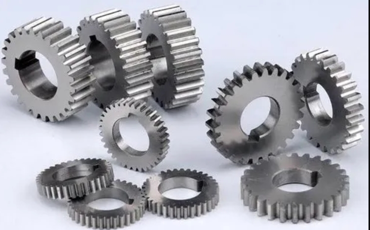
Spur gears are fundamental and critical components in a vast array of mechanical transmission systems. Their operational reliability directly impacts the performance and longevity of machinery. During service, spur gear teeth are subjected to complex, multiaxial cyclic loading conditions arising from the meshing action, compounded by the tribological environment at the contact interface. Predicting the fatigue life of spur gears is therefore a challenging but essential task for design and maintenance. Traditional models often simplify the contact to dry or perfectly lubricated Hertzian conditions and rely on uniaxial stress assumptions, which may not capture the true failure mechanisms. This study presents a comprehensive, physics-based model for predicting the fatigue life distribution of involute spur gears, explicitly integrating transient elastohydrodynamic lubrication (EHL) analysis with a multiaxial fatigue criterion that accounts for material properties and the complete stress history experienced by subsurface material points.
The core innovation of this approach lies in its sequential integration of three sophisticated modeling stages: a finite line-contact EHL model to determine the interfacial pressures and shear stresses, a subsurface stress calculation based on these surface tractions, and a multiaxial fatigue analysis utilizing the complete stress history of fixed material points within the gear tooth. This methodology moves beyond calculating a single bulk life value for the gear, enabling the prediction of a detailed fatigue life contour map throughout the entire tooth volume and across the complete meshing cycle. A key focus is investigating the significant influence of surface roughness, a ubiquitous manufacturing feature, on the resulting contact pressure, stress field, and ultimately, the predicted fatigue life of the spur gear.
Geometric and Kinematic Analysis of Spur Gear Meshing
The contact between two spur gear teeth at any instant can be analyzed as the equivalent contact between two cylindrical rollers with time-varying radii. The geometry of an involute spur gear pair in mesh is fundamental to defining the input parameters for the EHL model. Consider a pair in mesh at a generic point \(K\) along the line of action. The following parameters govern the instantaneous contact condition:
Let \(Z_1\), \(Z_2\) be the number of teeth on the pinion and gear, respectively; \(m\) be the module; \(\alpha\) be the standard pressure angle; and \(\omega_1\) be the angular velocity of the pinion. The base circle radius for the pinion is \(r_{b1} = (m Z_1 \cos\alpha)/2\). At the meshing point \(K\), the pressure angle is \(\alpha_{K1}\). The radius of curvature for the pinion tooth profile at \(K\) is given by:
$$R_{K1} = r_{b1} \cdot \tan\alpha_{K1}$$
Similarly, for the driven gear with base radius \(r_{b2}\), the radius of curvature is:
$$R_{K2} = r_{b2} \cdot \tan\alpha_{K2}$$
The equivalent radius of curvature \(R_K\), a critical parameter for contact mechanics, is:
$$R_K = \frac{R_{K1} \cdot R_{K2}}{R_{K1} + R_{K2}}$$
The surface velocities in the tangential direction at point \(K\) for the two gears are \(V_{K1} = \omega_1 R_{K1}\) and \(V_{K2} = \omega_2 R_{K2} = \omega_1 (Z_1/Z_2) R_{K2}\). The entrainment velocity \(U_K\), which drives lubricant into the contact, and the slide-to-roll ratio \(SRR_K\), which governs sliding friction, are defined as:
$$U_K = \frac{V_{K1} + V_{K2}}{2}$$
$$SRR_K = \frac{V_{K1} – V_{K2}}{U_K}$$
The normal load per unit width \(w(t)\) varies along the line of action according to the gear loading and the number of tooth pairs in contact. These parameters—\(R_K\), \(U_K\), \(SRR_K\), and \(w(t)\)—are continuously updated throughout the meshing cycle to feed the transient EHL model for the spur gear contact.
| Parameter | Pinion (Driver) | Gear (Driven) |
|---|---|---|
| Number of Teeth, \(Z\) | 39 | 18 |
| Module, \(m\) (mm) | 7 | |
| Pressure Angle, \(\alpha\) (°) | 20 | |
| Face Width, \(B\) (mm) | 32 | |
| Power, \(P\) (kW) | 1000 | |
| Rotational Speed, \(n\) (rpm) | 8000 | – |
| Torque, \(T\) (Nm) | 1193.6 | – |
Finite Line-Contact Elastohydrodynamic Lubrication Model
The lubricated contact between spur gear teeth is modeled as a finite line-contact EHL problem. The governing equations are solved for each instantaneous contact position corresponding to a specific point \(K\) along the path of contact. The model is based on the unified Reynolds equation approach, which robustly handles both full-film and mixed lubrication regimes.
1. Reynolds Equation:
The pressure distribution \(p(x,y,t)\) within the lubricant film is governed by the transient Reynolds equation:
$$
\frac{\partial}{\partial x}\left( \frac{\rho h^3}{\eta} \frac{\partial p}{\partial x} \right) + \frac{\partial}{\partial y}\left( \frac{\rho h^3}{\eta} \frac{\partial p}{\partial y} \right) = 12 \frac{\partial}{\partial x}(\rho U h) + 12 \frac{\partial}{\partial t}(\rho h)
$$
where \(h\) is the film thickness, \(\eta\) is the lubricant viscosity, \(\rho\) is the lubricant density, and \(U\) is the entrainment velocity.
2. Film Thickness Equation:
The film thickness \(h(x,y,t)\) accounts for the geometry of the contacting cylinders, the elastic deformation of the tooth surfaces \(v(x,y,t)\), and the surface roughness \(s_a(x,y)\):
$$
h(x,y,t) = h_0(t) + \frac{x^2}{2R_K(t)} + v(x,y,t) + s_a(x,y)
$$
The elastic deformation \(v\) is calculated from the pressure distribution using the Boussinesq integral, efficiently evaluated via the Discrete Convolution and Fast Fourier Transform (DC-FFT) method:
$$
v(x,y,t) = \frac{2}{\pi E’} \iint_{\Omega} \frac{p(\xi, \lambda, t)}{\sqrt{(x-\xi)^2 + (y-\lambda)^2}} d\xi d\lambda
$$
where \(E’\) is the equivalent elastic modulus \(\left( \frac{1}{E’} = \frac{1-\nu_1^2}{E_1} + \frac{1-\nu_2^2}{E_2} \right)\).
3. Load Balance Equation:
The integrated pressure must support the applied normal load per unit width \(w(t)\):
$$
w(t) = \iint_{\Omega} p(x,y,t) \, dx \, dy
$$
4. Lubricant Properties:
The pressure-dependence of lubricant density and viscosity is modeled using the Dowson-Higginson and the Barus (or Roelands) equations, respectively:
$$
\rho(p) = \rho_0 \left( 1 + \frac{0.6 \times 10^{-9} p}{1 + 1.7 \times 10^{-9} p} \right)
$$
$$
\eta(p) = \eta_0 \exp\left\{ (\ln \eta_0 + 9.67) \left[ (1 + 5.1 \times 10^{-9} p)^{z} – 1 \right] \right\}, \quad z = \frac{\alpha}{5.1 \times 10^{-9}(\ln \eta_0 + 9.67)}
$$
where \(\rho_0\) and \(\eta_0\) are ambient density and viscosity, and \(\alpha\) is the pressure-viscosity coefficient.
The system of equations is solved numerically using a line-relaxation iterative scheme coupled with the DC-FFT technique for deformation. This model provides the complete time-varying pressure \(p(x,y,t)\) and shear stress \(\tau(x,y,t)\) distributions at the interface of the spur gear teeth contact, which serve as the primary loading input for the subsequent fatigue analysis.
Subsurface Stress Field and Stress History Acquisition
The pressure and shear stress distributions obtained from the EHL model act as surface tractions on the semi-infinite elastic body representing the gear tooth. The resulting three-dimensional subsurface stress field \(\sigma_{ij}(x,y,z,t)\) is calculated using the convolution integral method with the corresponding Green’s functions \(G_{ij}^{N}\) and \(G_{ij}^{S}\) for normal and shear loading, respectively:
$$
\sigma_{qr}(x,y,z,t) = \iint_{\Omega} \left[ p(\xi,\eta,t) G_{qr}^{N}(x-\xi, y-\eta, z) + \tau(\xi,\eta,t) G_{qr}^{S}(x-\xi, y-\eta, z) \right] d\xi d\eta
$$
where \(q, r = x, y, z\). This computation is also accelerated using the DC-FFT algorithm.
A critical aspect for fatigue life calculation is obtaining the complete stress history \(\sigma_{ij}(t)\) for a fixed material point \(A\) located at coordinates \((X_A, Y_A)\) beneath the tooth surface. As the spur gear meshes, the computational domain (the contact patch) moves along the tooth flank. Therefore, the stress experienced by point \(A\) at time \(t+\Delta t\) corresponds to the stress calculated at a different spatial location within the computational domain at time \(t\). The relationship is governed by the rolling/sliding kinematics:
$$
x'(t+\Delta t) = x(t) + V_{roll}(t) \cdot \Delta t
$$
$$
y’ = y
$$
where \(V_{roll}\) is effectively the velocity of the contact patch along the tooth profile relative to the material. Thus, the stress history for point \(A\) with initial coordinate \(x_0\) at \(t=0\) is:
$$
\sigma_{ij}^{A}(t) = \sigma_{ij} \left( x_0 + \int_{0}^{t} V_{roll}(\zeta) d\zeta, \, Y_A, \, z_A, \, t \right)
$$
By tracking numerous fixed points within a volume of interest beneath the tooth surface, the complete multiaxial stress histories for all potential fatigue initiation sites are assembled.
Multiaxial Fatigue Life Prediction Model
To predict fatigue life under the complex, non-proportional multiaxial stress histories experienced by a spur gear tooth, a critical plane-based model known as the Characteristic Plane approach is employed. This model considers material properties and distinguishes between the fatigue crack initiation plane and a derived “characteristic plane” on which life calculations are performed.
The model is based on a fatigue damage parameter \(\beta\) defined on the characteristic plane:
$$
\beta = \sqrt{ \left( \frac{\sigma_{a}^{c}}{f_{-1}} \right)^2 + \left( \frac{\tau_{a}^{c}}{t_{-1}} \right)^2 + k \left( \frac{\sigma_{H,a}^{c}}{f_{-1}} \right)^2 }
$$
where:
- \(\sigma_{a}^{c}\), \(\tau_{a}^{c}\), and \(\sigma_{H,a}^{c}\) are the alternating normal stress, alternating shear stress, and alternating hydrostatic stress amplitudes on the characteristic plane, respectively.
- \(f_{-1}\) and \(t_{-1}\) are the fully reversed bending and torsional fatigue limits of the material.
- \(k\) is a material parameter.
The characteristic plane is defined as the plane where the mean hydrostatic stress over a cycle is zero. It is oriented at an angle \(\theta\) from the hypothesized physical crack initiation plane (assumed to be the plane of maximum normal stress amplitude). The angle \(\theta\) and the parameter \(\beta\) are derived from pure bending and pure torsion fatigue limits via the material constant \(e = t_{-1}/f_{-1}\):
$$
\cos(2\theta) = \frac{-2 + \sqrt{4 – 4(1/e^2 – 3)(5 – 1/e^2 – 4e^2)}}{2(5 – 1/e^2 – 4e^2)}
$$
$$
\beta = \left[ \cos^2(2\theta) s^2 + \sin^2(2\theta) \right]^{1/2}
$$
where \(s\) is a model parameter related to \(e\).
To incorporate mean stress effects and link to the material S-N curve, the damage parameter is reformulated into an equivalent stress amplitude \(\sigma_{eq,a}\):
$$
\sigma_{eq,a} = \beta^{-1} \sqrt{ \left[ \sigma_{a}^{c} \left( 1 + \eta \frac{\sigma_{m}^{c}}{f_{N_f}} \right) \right]^2 + \left( \frac{f_{N_f}}{t_{N_f}} \right)^2 (\tau_{a}^{c})^2 + k (\sigma_{H,a}^{c})^2 }
$$
where:
- \(\sigma_{m}^{c}\) is the mean normal stress on the characteristic plane.
- \(\eta\) is a material coefficient for mean stress sensitivity.
- \(f_{N_f}\) and \(t_{N_f}\) are the bending and torsion fatigue strengths at the desired life \(N_f\) (obtained from the material S-N curves: \(f_{N_f} \cdot N_f^b = C_1\), \(t_{N_f} \cdot N_f^b = C_2\)).
The life \(N_f\) is found by iteratively solving the equation \(\sigma_{eq,a} = f_{N_f}\). The shear stress amplitude \(\tau_{a}^{c}\) on the characteristic plane is determined from the stress history using the Minimum Circumscribed Circle method applied to the shear stress vector trajectory.
Results and Analysis: Influence of Surface Roughness
The integrated model is applied to analyze the spur gear pair described in Table 1. The numerical domain for the EHL solution is \(\{-4.5 \leq x/a \leq 2.5, -1 \leq y/(B/2) \leq 1, 0 \leq z/a \leq 1\}\), where \(a\) is the Hertzian half-width at the pitch point. The subsurface stress and fatigue analysis focuses on a volume extending to a depth of \(1a\). Artificially generated rough surfaces with different root-mean-square (RMS) amplitudes are superimposed on the ideal tooth profile to study the effect of roughness on spur gear fatigue life.
EHL Pressure and Stress at the Pitch Point:
The EHL solutions at the pitch point for smooth and rough surfaces reveal dramatic differences. For a smooth spur gear tooth contact, the pressure distribution is a smooth, elongated Hertz-like profile with a maximum pressure of approximately 1.6 GPa. Introducing surface roughness with an RMS amplitude of 0.2 µm causes severe pressure fluctuations, with local asperity pressures spiking to over 5.1 GPa. Consequently, the subsurface stress field \(\sigma_{zz}\) beneath these micro-contacts shows significant local concentrations and gradients, unlike the smooth, gradually varying stress field of the smooth contact case.
Stress History of a Subsurface Point:
The multiaxial stress history for a fixed material point located at a depth of \(0.16a\) below the pitch point surface was extracted. For the smooth spur gear contact, the stress components follow a parabolic-like curve as the contact zone passes over the point. In the rough contact case, the stress history becomes highly oscillatory, with much larger amplitude variations in the normal stress components due to the passing of individual asperity pressure spikes. This irregular, high-amplitude loading history is a key driver for reduced fatigue life.
Fatigue Life Distribution in the Spur Gear Tooth:
The model’s primary output is the predicted fatigue life (\(N_f\)) distribution within the tooth volume over a complete meshing cycle. The analysis yields contour maps of life as a function of position along the path of contact (from root to tip) and depth below the surface.
- Smooth & Low Roughness (Ra ≈ 0.05 µm): The minimum fatigue life occurs in the subsurface region at a depth of approximately \(0.2a\) to \(0.3a\) (about 0.056 mm) below the surface, near the pitch line. This aligns well with classical observations of subsurface-originated pitting failure in spur gears. The low-life region is confined subsurface.
- Moderate Roughness (Ra = 0.2 µm): The region of shortest life expands and shifts closer to the surface. The stress concentrations from roughness begin to dominate, making near-surface material more susceptible to fatigue crack initiation.
- High Roughness (Ra = 0.4 µm): The effect is profound. The zone of minimum fatigue life reaches the very surface of the spur gear tooth. Furthermore, this critically short-life region extends from the pitch line across nearly the entire single-tooth contact zone (the region between the start and end of single pair tooth contact). This predicts a high probability of surface-originated pitting or spalling over a large portion of the tooth flank.
The trend is clearly visualized in life-versus-depth plots at the pitch point. For roughness amplitudes below about 0.1 µm, the life curve closely follows the smooth case. As roughness increases to 0.4 µm, the life curve drops significantly at all depths, and its minimum point shifts sharply towards the surface. This highlights a critical finding: reducing spur gear surface roughness dramatically improves fatigue life, but there is a diminishing return. Polishing the surface beyond a certain smoothness threshold yields minimal additional life benefit, which is valuable for setting cost-effective manufacturing specifications for spur gears.
Conclusion
This study has established a comprehensive framework for predicting the multiaxial fatigue life of spur gears operating under realistic elastohydrodynamic lubrication conditions. The model successfully integrates transient finite-line contact EHL analysis, detailed subsurface stress calculation via convolution, and an advanced stress-history-based multiaxial fatigue criterion. Its key advantage is the ability to generate a spatial distribution of fatigue life within the spur gear tooth, offering far greater insight than a single life-value estimate.
The investigation into surface roughness effects provides critical practical insights for spur gear design and manufacturing. The results demonstrate that surface roughness is a dominant factor influencing contact fatigue performance of spur gears. Increased roughness amplitude leads to elevated and fluctuating contact pressures, which shift the maximum subsurface stresses towards the surface. This, in turn, causes the region of shortest predicted fatigue life to migrate from the traditional subsurface zone to the surface itself and to expand across the active tooth flank. Consequently, spur gears with poor surface finish are prone to widespread surface-initiated pitting. Conversely, achieving a high-quality surface finish significantly enhances spur gear durability, although the benefits plateau beyond a certain smoothness level. This model provides a quantitative tool to optimize this balance between spur gear performance and manufacturing cost.
Future extensions of this model could incorporate the effects of plastic deformation at asperity contacts under very high loads, the influence of non-metallic inclusions in the material, and the impact of lubricant additives and tribofilms on surface traction and fatigue mechanisms, further refining the life prediction accuracy for spur gears in demanding applications.