
In my extensive experience within the gear manufacturing industry, particularly in the production of high-precision gear components for heavy machinery, I have frequently encountered a persistent challenge in the gear cutting process: interference marks on the flank of conical gear shafts. These shafts, often integral to reducer units, are manufactured using the advanced Klingelnberg gear system. After processes like carburizing, quenching, and subsequent hard finishing, the tooth flank surface roughness can achieve values below Ra 0.8 μm. However, a significant portion of these conical gear shafts exhibited a troubling dark patch, or “black skin,” at the minor end of the tooth after hard skiving. This area remained uncut by the hard finishing tool, and attempts to adjust hard cutting parameters consistently failed to eliminate it. From a quality perspective, under operational loading conditions, the contact pattern extends, and this uncut region can severely compromise contact precision, leading to increased noise levels in the reducer. Aesthetically, it is akin to a flaw on an otherwise pristine surface, potentially tarnishing the product’s reputation. This issue prompted a deep dive into the intricacies of the gear cutting process to identify root causes and implement effective solutions.
The Klingelnberg gear system, introduced internationally in the 1980s, represents a sophisticated standard. While technical barriers have lessened over time, a complete mastery and digestion of its nuances within domestic manufacturing contexts has sometimes lagged, leading to phenomena like the interference described. Our company undertook substantial experimental research, drawing from limited available documentation, to analyze design parameter calculations, gear cutting adjustment parameters, and tooling. This journey has yielded valuable insights into mitigating interference, thereby enhancing product quality. The core of the problem lies in the fundamental interaction between the gear geometry, the machining strategy, and the gear cutting parameters.
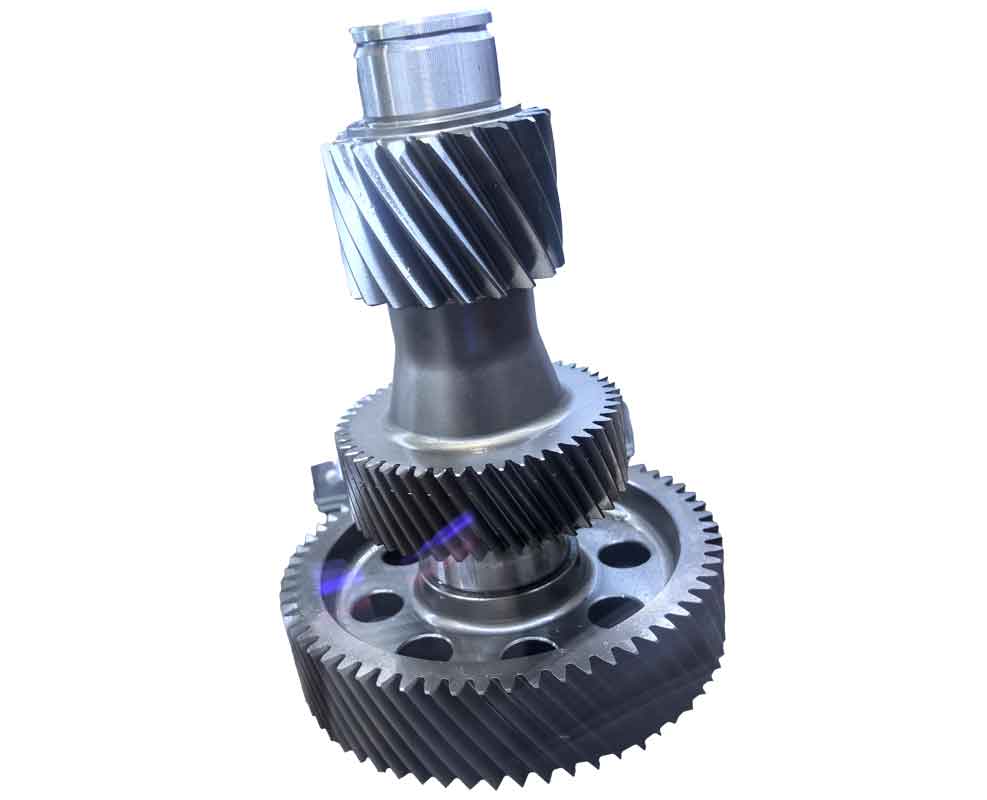
The genesis of this gear cutting interference is deeply rooted in the geometrical design of the conical gear shaft. According to Klingelnberg gear theory, to ensure an effective tooth face width, a specific triangular area at the junction of the shaft body and the minor end of the gear should ideally be removed. This area is essentially superfluous to the functional tooth flank. However, most conical gear shaft designs retain this extra material, as illustrated in the common structural configuration. This practice is adopted primarily to enhance the shaft’s structural strength, improve visual appeal, and reduce machining costs. Our experiments revealed that under identical design and initial gear cutting parameters, shafts with this retained triangular area frequently showed interference, whereas those machined to the theoretical ideal profile rarely did.
The interference mark corresponds precisely to this retained triangular zone. The analysis indicates that interference occurs because the cutting process parameters are calculated based on the ideal tooth flank geometry without this extra material. When the cutter path is programmed, it theoretically completes its work before engaging this region, leading to the observed uncut “black skin.” The fact that international manufacturers successfully produce shafts with this design without interference signifies that parameter adjustments can eliminate the issue. It highlights a gap in our full assimilation of contact pattern adjustment techniques within the Klingelnberg system. Crucially, our investigation pinpointed that the interference originates during the soft cutting or pre-hardening roughing phase of the gear cutting operation, specifically in the generating motion. Therefore, corrective actions must focus on this stage.
Furthermore, from a design calculation standpoint, gears whose parameters do not satisfy the Klingelnberg standard condition exhibit a higher probability of interference. This condition relates to the relationship between the mean cone distance, spiral angle, and tip radius. A detailed mathematical exploration is necessary here. The geometry of a conical gear is defined by several key parameters. The mean spiral angle $\beta_m$, the outer spiral angle $\beta_e$, the mean cone distance $R_m$, the outer cone distance $R_e$, and the cutter point radius $r$ are critical. The standard stipulates that for proper generation and avoidance of undercutting or interference, the following must hold:
$$ R_m \sin\beta_m < r < R_e \sin\beta_e $$
When $r$ falls outside this range, the kinematic conditions during gear cutting become suboptimal, increasing the risk of the tool failing to fully profile the tooth root at the minor end. The effective tooth depth $h_e$ and the theoretical clearance required at the minor end $c_{min}$ can be derived from these base parameters. The condition for interference-free generation can be expressed as a function of the tool geometry and workpiece setting. Let the tool tip circle radius be $r_{a0}$ and the workpiece root cone angle be $\delta_f$. The limit for interference at the minor end is reached when the tool path relative to the workpiece does not provide sufficient travel to cover the entire active profile. This can be modeled by examining the trajectory equation of the cutter blade during the generating roll. The coordinate of a point on the cutter edge in the machine coordinate system $(X_c, Y_c, Z_c)$ is transformed into the workpiece system $(X_w, Y_w, Z_w)$ through a series of rotations and translations dependent on the machine settings: eccentricity $E$, axial setting $X$, and the basic machine angle. The interference occurs if, for all points on the desired tooth flank at the minor end, there exists no parameter in the generating motion that brings the cutter edge into contact. Mathematically, for a point $P_w$ on the workpiece flank, we need to find a machine roll angle $\phi$ and cutter rotation angle $\theta$ such that:
$$ \min_{\phi, \theta} || T(\phi, \theta) \cdot P_c – P_w || = 0 $$
where $T$ is the transformation matrix encapsulating the gear cutting machine kinematics. If the solution set is empty for points in the triangular region, interference is inevitable. This is more likely when the tool radius $r$ is too large relative to the local curvature at the minor end, violating the inequality above.
To systematically address this, we developed and tested several improvement methods focused on modifying the soft cutting parameters. The primary adjustable parameters in the Klingelnberg gear cutting process that influence the root geometry and contact pattern are the crowning amount $C_b$, the eccentricity $E_{EXZ}$, and the resulting radius difference $EXB$. Through numerous trials, we established that carefully adjusting these parameters can significantly alleviate, if not completely eliminate, the hard skiving interference.
The crowning $C_b$ introduces a controlled modification to the tooth flank along its length. Increasing $C_b$ alters the depth of cut distribution, potentially allowing the cutter to engage slightly deeper into the critical minor end region during soft cutting. The eccentricity $E_{EXZ}$ directly changes the relative position between the cutter head and the workpiece axis, affecting the generating motion and the effective tool radius. Adjusting $E_{EXZ}$ modifies the $EXB$ value, which is the difference between the tool’s nominal radius and its effective cutting radius at the generation point. By increasing $EXB$ (often by increasing $E_{EXZ}$), we effectively provide the tool with a more favorable path to remove material from the troublesome triangular zone. However, these adjustments do not come without consequences. Changing $C_b$ and $EXB$ invariably shifts the contact pattern on the tooth flank, particularly in the spiral angle direction. Therefore, a compensatory adjustment is required. This is typically achieved by increasing the outer blade radius $r_{a0}$ and fine-tuning the mounting distance $A$ of the cutter head. This restores the contact pattern to its desired location and shape while preserving the interference correction.
The following table summarizes the key gear cutting parameters, their standard functions, and the adjustment strategy for interference mitigation:
| Parameter | Standard Role in Gear Cutting | Effect on Interference | Recommended Adjustment Direction to Reduce Interference |
|---|---|---|---|
| Crowning Amount ($C_b$) | Controls longitudinal tooth flank modification for load distribution. | Alters cut depth profile; can expose minor end to more material removal. | Increase moderately (e.g., +10% to +20% from nominal). |
| Eccentricity ($E_{EXZ}$) | Sets offset between cutter and workpiece axes; influences generation kinematics. | Directly changes effective tool path and $EXB$ value. | Increase to raise $EXB$ value. |
| Radius Difference ($EXB$) | Derived parameter affecting the effective cutting radius. | Higher $EXB$ allows tool to reach further into minor end root. | Increase via $E_{EXZ}$ adjustment. |
| Outer Blade Radius ($r_{a0}$) | Defines the tip circle of the cutting blades. | Compensates for spiral angle contact shift after $C_b$/$EXB$ changes. | Increase slightly to correct contact pattern. |
| Mounting Distance ($A$) | Axial distance setting for cutter head. | Fine-tunes contact pattern position. | Adjust empirically based on contact check. |
Another critical consideration in the broader gear cutting process is tool geometry selection, especially during the roughing or “blank cutting” phase. The tip width of the cutter $w_{a0}$ must be strictly less than the root chordal width of the tooth space $s_f$ at the minor end. If this condition is violated, $w_{a0} \ge s_f$, interference will occur during the rough cutting stage itself, leaving excessive material that subsequent finishing cannot rectify. The root space width can be calculated from the basic gear data: $s_f = p – e$, where $p$ is the circular pitch and $e$ is the tooth thickness at the root. In terms of module $m_n$ and number of teeth $z$, and accounting for helix angle $\beta$, a simplified check is:
$$ w_{a0} < \frac{\pi m_n}{\cos\beta} – s_f $$
Ensuring this inequality holds is a fundamental prerequisite for interference-free gear cutting from the outset.
The integration of advanced cutting tools for secondary operations is also paramount in achieving overall quality and efficiency in gear manufacturing. In our production lines, addressing burrs and edge preparation is equally critical. The presence of burrs and sharp edges after gear cutting or other machining operations can be detrimental. They are potential initiation sites for stress concentration and fatigue cracks. Loose burrs can contaminate working surfaces, affecting performance and assembly. Furthermore, improper chamfering or misaligned counterbores can induce bending moments in fastened joints. Traditionally, deburring and chamfering both sides of a through-hole required flipping the part and re-fixturing, which is time-consuming and introduces positional errors, especially for large or asymmetrical components.
To streamline this, we have adopted highly efficient and precise combined cutting tools that can perform multiple operations in a single pass. For instance, tools designed for simultaneous deburring and chamfering of both entry and exit sides of a hole in one stroke eliminate the need for part reorientation. The working principle often involves spring-loaded or mechanically guided cutting elements that deploy sequentially or simultaneously. The cutting force and feed motion activate these elements. For a through-hole of diameter $D$, a tool with a pilot section and opposing cutters can produce a chamfer of angle $\alpha$ and depth $d$ on both sides. The relationship between feed force $F_f$, cutter geometry, and material properties determines the quality. The chamfer width $C_w$ is related to the depth $d$ and angle $\alpha$ by:
$$ C_w = \frac{d}{\tan(\alpha/2)} $$
These tools significantly reduce non-productive time and improve consistency, which complements the precision achieved in the primary gear cutting process. They are essential for finishing the auxiliary features on gear housings, bearing seats, and bolt holes associated with gear assemblies.
To further elaborate on the gear cutting interference solution, let’s consider a quantitative example. Suppose a conical gear shaft has the following nominal design parameters: Mean cone distance $R_m = 150\,mm$, Outer cone distance $R_e = 180\,mm$, Mean spiral angle $\beta_m = 25^\circ$, Outer spiral angle $\beta_e = 30^\circ$, and the cutter point radius initially set at $r = 70\,mm$. First, we check the Klingelnberg condition:
$$ R_m \sin\beta_m = 150 \times \sin(25^\circ) \approx 63.4\,mm $$
$$ R_e \sin\beta_e = 180 \times \sin(30^\circ) = 90\,mm $$
Since $63.4 < 70 < 90$, the condition is satisfied, yet interference might still occur due to the retained triangle. Now, we adjust the soft cutting parameters. The initial crowning $C_{b0}$ was 0.015 mm, eccentricity $E_{EXZ0}$ was 45 mm, giving $EXB_0 \approx 0.12\,mm$. After observation of interference, we increase $C_b$ to 0.018 mm and $E_{EXZ}$ to 47 mm, which raises $EXB$ to approximately 0.15 mm. This adjustment is applied during the soft gear cutting cycle. Post-adjustment, the hard skiving operation shows a marked reduction in the minor end black patch. A subsequent contact pattern check on a testing machine might show a slight shift toward the toe. To correct this, we increase the outer blade radius from its nominal $r_{a0}=105\,mm$ to $106\,mm$ and adjust the mounting distance $A$ by +0.1 mm. The final result is a gear tooth free of interference and with a correctly centered contact pattern.
The interplay between parameters can be complex. The table below illustrates a more detailed experimental matrix from our trials, showing the effect of combined parameter changes on interference severity and contact pattern location. Interference severity is rated on a scale from 0 (none) to 5 (severe uncut area). Contact pattern shift is noted as toward Heel (H), Toe (T), or Central (C).
| Trial # | $C_b$ (mm) | $E_{EXZ}$ (mm) | $EXB$ (mm) | Interference Severity (0-5) | Contact Pattern Shift | Corrective Action on $r_{a0}$ & $A$ |
|---|---|---|---|---|---|---|
| 1 (Baseline) | 0.015 | 45.0 | 0.120 | 4 | C | N/A |
| 2 | 0.018 | 45.0 | 0.125 | 3 | Slight to T | Minor increase in $A$ |
| 3 | 0.018 | 46.5 | 0.145 | 2 | Moderate to T | Increase $r_{a0}$ by 0.5 mm |
| 4 | 0.020 | 47.0 | 0.150 | 1 | Significant to T | Increase $r_{a0}$ by 1.0 mm, adjust $A$ +0.15mm |
| 5 | 0.022 | 47.5 | 0.155 | 0 | To T, then corrected | Increase $r_{a0}$ by 1.2 mm, $A$ +0.2mm (Final) |
From this data, a trend is clear: increasing both $C_b$ and $E_{EXZ}$ (and thus $EXB$) reduces interference severity but drives the contact pattern toward the toe. The corrective increases in outer blade radius and mounting distance successfully pull the pattern back toward the center. This iterative, empirical approach is often necessary because the exact mathematical modeling of the contact shift is highly nonlinear and depends on the specific machine tool and cutter head design.
Beyond parameter adjustment, the gear cutting process itself must be viewed holistically. The stability of the machining system, including the rigidity of the workpiece fixture, the condition of the cutter blades, and the cutting fluid application, all contribute to the final outcome. For instance, tool wear on the soft cutting blades can mimic the effects of improper parameter settings, leading to insufficient stock removal at the minor end. Regular tool inspection and maintenance are vital. The cutting forces involved in gear cutting can be significant. A simplified model for the tangential cutting force $F_t$ during hobbing or skiving can be expressed as:
$$ F_t = k_c \cdot a_p \cdot f_z \cdot z_c $$
where $k_c$ is the specific cutting force of the material, $a_p$ is the depth of cut, $f_z$ is the feed per tooth, and $z_c$ is the number of cutter blades engaged. Excessive force can cause deflection, altering the effective tool path. Ensuring parameters are within machine and tool limits is crucial.
The journey to master the Klingelnberg gear cutting process and eliminate interference has been one of meticulous experimentation and analysis. It underscores the importance of not just importing advanced technology but fully understanding its underlying principles. The interference issue in conical gear shafts is predominantly influenced by design parameters that include the retained material at the minor end. However, through strategic modification of the soft gear cutting parameters—specifically the crowning amount $C_b$ and the eccentricity $E_{EXZ$ to alter the radius difference $EXB$—significant improvement can be achieved. The consequent shifts in the contact pattern must then be managed by adjusting the outer blade radius and mounting distance. Additionally, vigilant attention must be paid during the initial gear cutting planning stages to ensure the cutter tip width is less than the root space width, preventing interference in the roughing phase.
This knowledge has been instrumental in elevating our product quality. The integration of such precise gear cutting techniques with complementary high-efficiency finishing tools for deburring and chamfering creates a robust manufacturing ecosystem. It ensures that every component, from the intricate gear teeth to the simplest bolt hole, meets the highest standards of precision and reliability. The continuous refinement of these processes remains a key focus, driving innovation and excellence in gear manufacturing. The experience gained reaffirms that challenges in gear cutting are often solvable through a combination of theoretical analysis, empirical adjustment, and a willingness to delve deep into the mechanics of the machining process.