
In the field of mechanical power transmission, screw gear drives, commonly realized as worm and gear sets, are prized for their high reduction ratios, compactness, and self-locking potential. However, their performance and longevity are critically dependent on precise conjugate action between the worm and the gear. A significant challenge arises in non-conjugate or “mismatched” pairings, where the gear is not generated by a hob identical to the worm. This report details a first-person investigation into a severe failure encountered in an industrial mismatched screw gear drive. Utilizing advanced modeling and simulation techniques, I aimed to uncover the root cause by analyzing the contact stress distribution across various meshing positions.
The problematic assembly consisted of a triple-start conical enveloping worm paired with a gear cut by a single-start normal straight-sided hob. This inherent mismatch means the theoretical line contact of a conjugate pair degenerates into a precarious point contact, leading to significantly elevated contact stresses. The primary objective of this study was to construct accurate digital models of this specific mismatched screw gear set and perform a static structural finite element analysis (FEA) to map the equivalent (von-Mises) stress field at different stages of the meshing cycle.
1. Parametric Foundation and 3D Modeling
The first and most crucial step was creating geometrically accurate 3D models. The parameters for the gear blank, the generating hob, and the worm are summarized in the table below. These dimensions form the bedrock of all subsequent modeling and analysis.
| Component | Parameter | Value | Unit |
|---|---|---|---|
| Gear Blank | Throat Diameter | 47.5 | mm |
| Tip Diameter | 49.0 | mm | |
| Pitch Diameter | 45.0 | mm | |
| Hob & Setup | Shaft Angle (Blank to Hob) | 77.93° | deg |
| Center Distance | 32.5 | mm | |
| Worm | Number of Starts | 3 | – |
Modeling the triple-start conical enveloping worm is a complex, procedural task. I followed a methodical approach involving the creation of the worm’s axial profile and its subsequent sweeping along a helical path with a defined lead, $L$, related to the pitch diameter $d$ and the lead angle $\lambda$ by:
$$ \lambda = \arctan\left(\frac{L}{\pi d}\right) $$
This ensures the worm model accurately represents the conical grinding wheel envelope process.
The gear model presented a greater challenge. Its tooth surface is a complex, non-standard geometry resulting from the machining (hobbing) process with the single-start hob. Direct geometric modeling is virtually impossible. Therefore, I employed a virtual manufacturing technique within SolidWorks. This method simulates the physical hobbing process:
- Assembly: The hob model and gear blank model were assembled with the precise shaft angle (77.93°) and center distance (32.5 mm).
- Boolean Subtraction: The hob was used as a cutting tool to perform a Boolean subtraction from the gear blank, simulating the cut for one angular position.
- Indexing Simulation: The hob was rotated by a discrete angular step (18°), and the gear blank was rotated correspondingly by a calculated smaller angle (0.5°, based on the ratio of 36 gear teeth). The Boolean operation was repeated.
- Iteration: This indexed cutting process was iterated until a complete, multi-tooth gear segment was generated. For the purpose of contact analysis, a segment containing four full teeth was deemed sufficient.
This virtual machining is computationally intensive but yields a highly accurate representation of the actual gear tooth form, crucial for a meaningful contact analysis of this mismatched screw gear system.
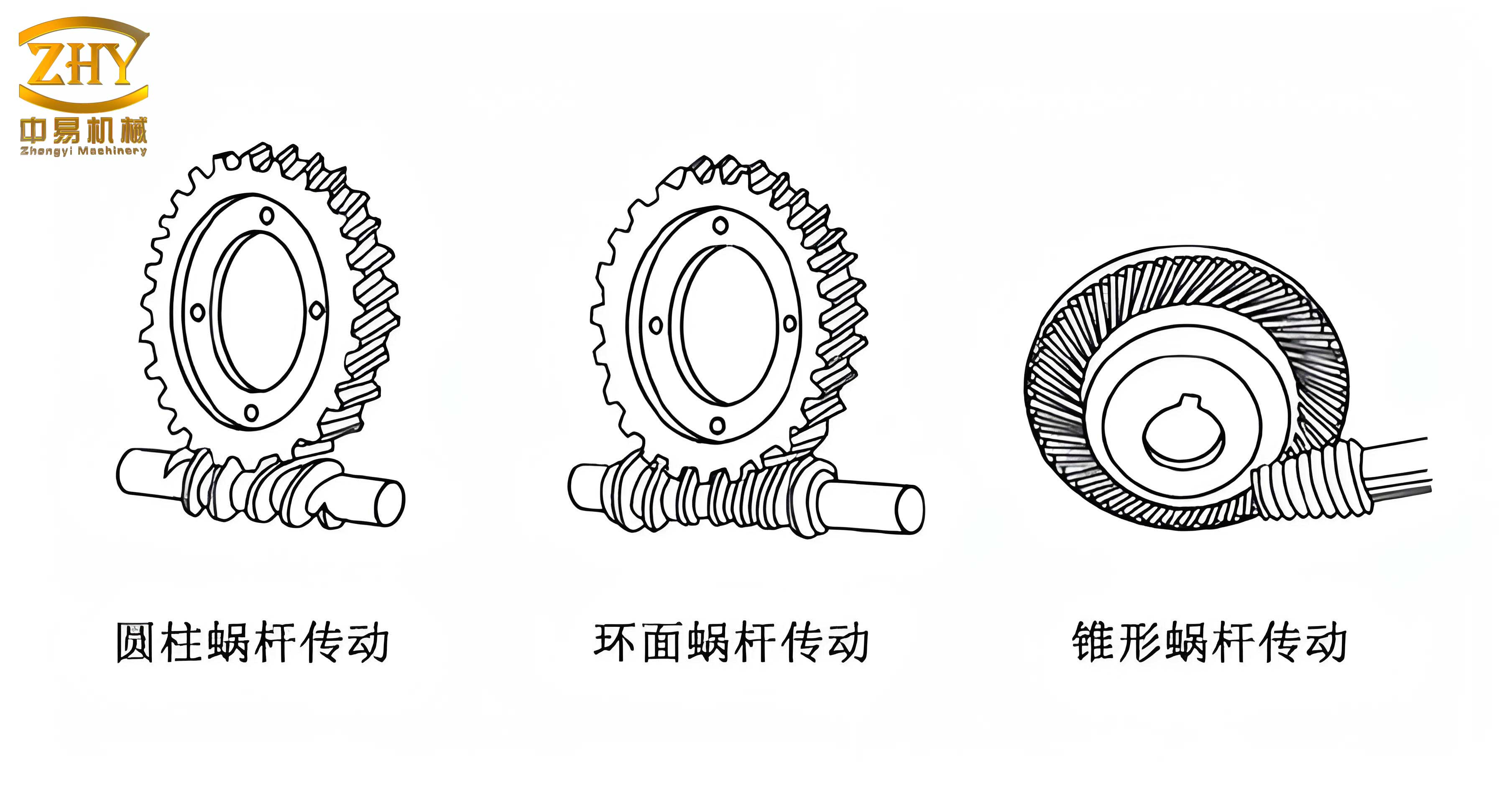
2. Finite Element Analysis Setup
The assembled screw gear model was imported into ANSYS Workbench, which excels at handling complex, dirty CAD geometry often resulting from Boolean operations. The analysis was set up as a static structural simulation.
2.1 Material Properties and Meshing
Accurate material definitions are essential for reliable FEA results. The chosen materials and their key properties are listed below.
| Component | Material | Young’s Modulus, $E$ | Poisson’s Ratio, $\nu$ | Yield Strength, $\sigma_y$ |
|---|---|---|---|---|
| Worm | 40Cr (Quenched & Tempered) | 206 GPa | 0.28 | ≥ 785 MPa |
| Gear | ZCuAl8Mn13Fe3Ni2 | 124.1 GPa | 0.34 | 310 – 370 MPa |
The contact region between the worm and gear was automatically detected. A frictional contact formulation was applied to the interacting tooth surfaces. A curvature-relevant, fine mesh was generated, with refinements in the expected contact zones to capture the high stress gradients accurately. The resulting finite element model consisted of a high number of tetrahedral and hexahedral elements.
2.2 Boundary Conditions and Loading
The operating conditions were derived from the application: an input power of 72 W at a worm rotational speed of 3300 rpm. This translates to an input torque, $T_{worm}$:
$$ T_{worm} = \frac{P}{\omega} = \frac{72 \text{ W}}{2\pi \times 3300 / 60 \text{ rad/s}} \approx 0.208 \text{ Nm} = 208 \text{ Nmm} $$
The boundary conditions were applied as follows:
- Gear: A “Fixed Support” was applied to the inner surface of the gear’s hub bore, preventing all translational and rotational degrees of freedom.
- Worm: A “Cylindrical Support” was applied to the worm shaft, allowing only rotation about its axis. One end face of the worm shaft was also fixed to prevent axial movement.
- Load: The calculated torque of 208 Nmm was applied to the worm shaft.
This setup simulates the gear as the fixed, driven member and the worm as the powered input member.
3. Stress Analysis at Discrete Meshing Positions
The meshing action of a screw gear is a continuous process. To understand how the stress state evolves, I analyzed five distinct, representative meshing positions. This involved rotating both the worm and the gear models from a defined starting assembly by calculated angular increments to simulate different phases of engagement for a single tooth pair.
For each position, a nonlinear static FEA was solved. The primary output was the contour plot of equivalent (von-Mises) stress, $\sigma_{eq}$, calculated at every node in the model. The von-Mises stress is an effective measure for predicting yielding in ductile metals and is given by:
$$ \sigma_{eq} = \sqrt{\frac{1}{2}[(\sigma_1 – \sigma_2)^2 + (\sigma_2 – \sigma_3)^2 + (\sigma_3 – \sigma_1)^2]} $$
where $\sigma_1$, $\sigma_2$, and $\sigma_3$ are the principal stresses.
The maximum equivalent stress values on both the gear and the worm for all five positions were extracted and are compiled in the table below. Position 3 represents the initial assembly configuration.
| Meshing Position | Description of Engagement Phase | Max $\sigma_{eq}$ on Gear (MPa) | Max $\sigma_{eq}$ on Worm (MPa) |
|---|---|---|---|
| Position 1 | Initial contact near the gear tooth root / worm tooth tip. | 352.4 | 721.8 |
| Position 2 | Early engagement, load zone shifting. | 361.7 | 698.5 |
| Position 3 | Mid-range engagement, contact near gear tooth center. | 346.2 | 635.4 |
| Position 4 | Late engagement, load moving towards gear tooth root. | 368.9 | 744.1 |
| Position 5 | Final contact near gear tooth root / worm tooth tip. | 355.6 | 765.3 |
4. Discussion of Results and Failure Mechanism
The FEA results provide a clear and quantitative explanation for the observed catastrophic failure of the mismatched screw gear drive. The analysis reveals several critical insights:
1. Chronically High Gear Stresses: Across all five meshing positions, the maximum equivalent stress on the gear tooth consistently exceeds the yield strength of the bronze material (310-370 MPa). Position 4 shows a peak of 368.9 MPa, which is at the very upper limit or above the material’s capacity. This indicates that plastic deformation and progressive yielding of the gear teeth are inevitable during operation, leading to rapid wear, pitting, and ultimately, tooth fracture. The contact stress, $\sigma_H$, in gear teeth is classically related to load and geometry by a formula akin to:
$$ \sigma_H = Z_E \sqrt{\frac{F_t K_A K_V K_{H\beta}}{d_1 b} \cdot \frac{u+1}{u}} $$
where $Z_E$ is the elasticity factor, $F_t$ is the tangential load, and the $K$ factors account for application, dynamic, and load distribution effects. In this mismatched screw gear, the poor load distribution factor $K_{H\beta}$ due to point contact is likely the dominant reason for the excessive $\sigma_H$, which correlates with the high $\sigma_{eq}$ we observed.
2. Severe Stress Concentration on the Worm: More alarmingly, the stress on the hardened steel worm is exceedingly high, reaching between 635 MPa and 765 MPa. While the worm material has a higher yield strength (≥785 MPa), these stress levels are dangerously close to its limit, especially considering potential stress concentrations from manufacturing imperfections and the cyclic nature of loading. The stress pattern consistently shows that the load is borne by a very small area on the worm thread flank—either near the tip (Positions 1, 2, 4, 5) or the root (Position 3). This extreme localization of stress is the hallmark of the non-conjugate, point-contact condition in this mismatched pair.
3. Dynamic Stress Fluctuation: The significant variation in maximum stress values from one meshing position to another (e.g., worm stress from 635 MPa to 765 MPa) underscores the dynamic and unstable nature of the contact in a mismatched screw gear. Unlike a well-designed conjugate pair with a smooth load transfer, this drive experiences sharp impacts and shifting load zones as teeth engage and disengage, contributing to accelerated fatigue failure.
4. Correlation to Physical Failure: The FEA stress contours visually demonstrate the localized, high-intensity stress patches that explain the observed physical damage: severe wear and pitting on the bronze gear teeth and likely spalling or fracture initiation on the hardened worm threads. The simulation confirms that the design is fundamentally flawed due to the mismatch.
The following table summarizes the failure modes predicted by the analysis and their root cause:
| Component | Predicted Failure Mode | Primary Cause from Analysis |
|---|---|---|
| Gear (Bronze) | Plastic deformation, abrasive wear, pitting, tooth bending fatigue fracture. | Sustained equivalent stress exceeding material yield strength in every meshing cycle. |
| Worm (Hardened Steel) | Surface fatigue (spalling), micro-pitting, and potential crack initiation at stress concentrators. | Extremely high localized contact stresses approaching the material’s yield limit due to point contact. |
| Drive System | Reduced efficiency, increased noise and vibration, catastrophic seizure or breakage. | Unstable, high-stress meshing action inherent to the non-conjugate screw gear geometry. |
5. Conclusion and Design Implications
This investigation successfully employed integrated CAD/CAE methodology to diagnose a critical failure in an industrial mismatched screw gear drive. The process of virtual gear generation provided an accurate model of the complex tooth geometry, while the subsequent finite element analysis in ANSYS Workbench delivered a detailed, quantitative stress map throughout the meshing cycle.
The results are unequivocal: the severe failure is a direct consequence of the fundamental geometric incompatibility between the triple-start conical enveloping worm and the single-start hob-generated gear. This mismatch forces the transmission of power through a highly localized point contact, generating equivalent stresses that consistently surpass the yield strength of the gear material and impose dangerously high stresses on the worm. The operational stress state is not only high but also highly variable, promoting rapid fatigue failure.
This analysis serves as a powerful theoretical and practical tool for designers. It conclusively demonstrates that such non-conjugate screw gear pairings are inherently risky and should be avoided in applications requiring reliability and durability. The methodology established here—combining virtual manufacturing for geometric fidelity with advanced nonlinear contact FEA—provides a robust framework for evaluating and optimizing screw gear designs before physical prototyping, thereby saving significant cost and time while preventing field failures. For any critical power transmission application, the use of a properly conjugate, matched worm and gear set is paramount to ensure the contact stresses are distributed over a designed line or area, keeping them within safe limits for the chosen materials.