
In the realm of mechanical power transmission, gear drives stand as a paramount solution due to their operational smoothness, excellent interchangeability, and adaptability through profile shifting. Among the various types, the involute spur gear, characterized by its simple construction, cost-effectiveness, and absence of axial thrust, is ubiquitously employed across numerous industrial and aerospace transmission systems. The accurate assessment of gear strength, particularly bending fatigue resistance, is a critical pillar of reliable design. Contemporary international standards, such as ISO and AGMA, consistently identify the tooth root fillet or transition curve as the locus of maximum bending stress. Consequently, the geometric profile of this region, specifically its curvature radius, exerts a profound influence on the magnitude of the root stress. A smaller root fillet radius typically acts as a stress concentrator, potentially precipitating premature failure under heavy loads. Therefore, establishing a precise mathematical model for the tooth root transition curve generated by standard manufacturing processes is indispensable for high-fidelity bending strength calculations and the design of robust, high-performance spur and pinion gear sets.
The primary methodology for generating gear teeth is the generating or hobbing process, which mimics the meshing action between a cutting tool and the gear blank. When a rack-shaped cutter is used, the tooth flank and the root fillet are produced simultaneously. The fillet itself is generated by the tip rounding of the rack cutter. Precise modeling of this curve has historically been challenging due to the complex relative motion involved. In this work, I employ a kinematic approach that synergizes the fundamentals of the gear generating process with the instantaneous center theorem (often referred to as the triple center theorem in kinematics) to develop a rigorous analytical model. This model enables the derivation of an exact formula for the curvature radius at any arbitrary point along the tooth root transition curve of a spur gear. Subsequently, I perform a detailed parametric study to elucidate the influence of key design variables—such as the number of teeth, profile shift coefficient, pressure angle, and addendum coefficient—on the minimum value of this curvature radius. The insights gleaned provide vital guidance for designers in optimizing the root geometry of both spur gears and mating pinions to enhance bending load capacity, especially in demanding applications like aerospace reducers where weight and reliability are paramount.
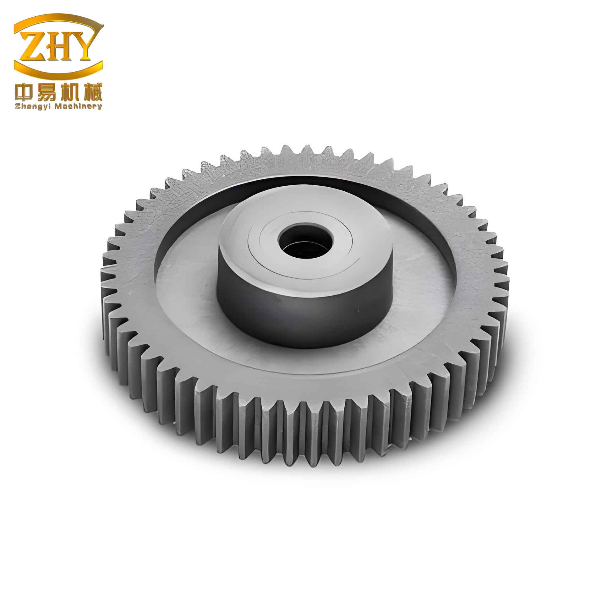
The generating process using a basic rack tool is the industry standard. The fundamental rack profile, which serves as the cutter, is defined by several parameters: the module \(m\), the pressure angle \(\alpha\), the addendum coefficient \(h_a^*\), the dedendum or bottom clearance coefficient \(c^*\), and the tip rounding radius \(\rho_0\). The generation is essentially a rolling motion without slip between the pitch line of the imaginary rack and the pitch circle of the gear being cut. During this process, the straight-sided flanks of the rack generate the involute profiles of the gear teeth, while the rounded tips of the rack cutter generate the non-involute trochoidal fillet at the tooth root. The shape of this fillet is not a simple circular arc but a trochoid, whose geometry is entirely determined by the motion and the tool profile. Accurately capturing this geometry is the first step towards stress analysis.
To derive the curvature radius, I begin with a detailed kinematic analysis of the generating motion. Consider a rack cutter moving with a constant translational velocity \(v_c\) along its pitch line. The gear blank rotates with a constant angular velocity \(\omega\) about its center \(O\), such that the pitch circle rolls without slipping on the pitch line. The point of tangency between the gear’s pitch circle and the rack’s pitch line is the pitch point \(P_0\). At any instant during the cutting of the fillet, the generating point \(K\) is located on the tip rounding of the rack cutter. This point \(K\) is in continuous contact with the gear blank, meaning its absolute velocity must satisfy the condition of no relative motion in the direction normal to the surface at the contact point. This kinematic constraint is the key to applying the instantaneous center theorem.
Let \(l_1\) be the common normal line at the contact point \(K\). For two bodies in rolling/sliding contact, the relative velocity at the contact point must lie in the common tangent plane, i.e., it has zero component along the common normal. Consequently, the absolute velocity vectors of point \(K\) considered as a point on the rack (\(\vec{v}_{K,r}\)) and as a point on the gear (\(\vec{v}_{K,g}\)) must have equal projections onto \(l_1\). The instantaneous center theorem states that for any two bodies in plane motion, there exists a point (the instantaneous center of rotation) where their relative velocity is zero. For the relative motion between the rack and the gear, we can find this instantaneous center \(C\). Since the rack has pure translation, its instantaneous center for rotation relative to the ground is at infinity perpendicular to \(v_c\). The gear rotates about \(O\). The relative instantaneous center \(C\) for the rack and gear lies on the line perpendicular to the relative velocity direction. A more direct approach for finding the curvature radius uses the concept of the center of curvature of the path that point \(K\) traces on the gear body (the fillet curve).
I define the following coordinate system: a fixed coordinate system attached to the gear blank with origin at \(O\), and a moving coordinate system attached to the rack cutter. The rack cutter’s tip rounding has a center point \(H\). The geometry is shown in the following diagram (described verbally as the figure link is provided). The parameter \(h\) represents the vertical distance from the tip rounding center \(H\) to the pitch line of the rack cutter. This distance \(h\) is not constant during generation if profile shifting is applied; it is given by \(h = (h_a^* + c^*)m – \rho_0 + x m\), where \(x\) is the profile shift coefficient (positive for addendum modification outward). However, during the generation of a specific point on the fillet, \(h\) is fixed for that instantaneous configuration. The angle \(\lambda\) is the angle between the common normal \(l_1\) at point \(K\) and the direction of the rack’s translation \(v_c\). This angle varies as the contact point moves along the tip rounding.
Applying the instantaneous center theorem to the motion of point \(K\) relative to the gear body yields the center of curvature \(Q\) of the path traced on the gear. This point \(Q\) lies at the intersection of specific lines constructed from the kinematics. The distance \(QK\) is precisely the curvature radius \(\rho_K\) of the gear’s root fillet at point \(K\). Through geometric analysis of similar triangles and kinematic relationships, the general formula for the curvature radius at any point on the transition curve is derived as:
$$ \rho_K = \rho_0 + \frac{h}{\sin \lambda} – \frac{h^2 \sin \lambda}{h \sin^2 \lambda + r} $$
where \(r\) is the pitch radius of the gear, \(r = mZ / 2\), with \(Z\) being the number of teeth. This formula is pivotal as it connects the tool geometry (\(\rho_0, h\)), the instantaneous contact geometry (\(\lambda\)), and the gear size (\(r\)) to the local fillet curvature.
The parameter \(\lambda\) changes continuously as the generating point moves from the start to the end of the fillet. At the very bottom of the fillet, where it blends into the root circle, the common normal \(l_1\) becomes perpendicular to the rack’s velocity direction. This corresponds to \(\lambda = 90^\circ\) or \(\pi/2\) radians. Substituting this value into the general formula gives the minimum curvature radius \(\rho_{\text{kmin}}\), which is often the most critical from a stress concentration perspective:
$$ \rho_{\text{kmin}} = \rho_0 + \frac{h^2}{h + r} $$
This elegant result shows that the minimum radius is always greater than the tool tip radius \(\rho_0\), as the second term is positive. It is a function of the basic gear and tool parameters. To aid designers, I now analyze how each parameter influences \(\rho_{\text{kmin}}\). For a baseline set of parameters, I choose a module \(m = 4 \text{ mm}\), pressure angle \(\alpha = 20^\circ\), tool tip radius \(\rho_0 = 1 \text{ mm}\) (assuming it satisfies clearance and tip thickness constraints), addendum coefficient \(h_a^* = 1\), and no initial profile shift (\(x=0\)). The number of teeth \(Z\) is varied to see its effect. The following table summarizes the calculation of \(\rho_{\text{kmin}}\) for different tooth counts, illustrating the trend. Note: \(r = 2Z\) since \(m=4\).
| Number of Teeth, \(Z\) | Pitch Radius, \(r\) (mm) | Distance \(h\) (mm) | Minimum Curvature Radius, \(\rho_{\text{kmin}}\) (mm) |
|---|---|---|---|
| 15 | 30 | 4 | 1 + 16/(4+30) ≈ 1.471 |
| 20 | 40 | 4 | 1 + 16/44 ≈ 1.364 |
| 30 | 60 | 4 | 1 + 16/64 ≈ 1.250 |
| 40 | 80 | 4 | 1 + 16/84 ≈ 1.190 |
| 50 | 100 | 4 | 1 + 16/104 ≈ 1.154 |
| 100 | 200 | 4 | 1 + 16/204 ≈ 1.078 |
The table clearly demonstrates that as the number of teeth increases, the minimum curvature radius decreases. This decrease is more pronounced for lower tooth counts and asymptotically approaches a limiting value as \(Z\) becomes very large (the rack limit). For a standard spur and pinion pair, where the pinion typically has a lower tooth count, this implies that the pinion’s root fillet will have a larger minimum curvature radius compared to a gear with many teeth, all else being equal. This is beneficial for the pinion, which often experiences higher stress cycles. The relationship can be expressed by substituting \(r = mZ/2\) into the formula:
$$ \rho_{\text{kmin}} = \rho_0 + \frac{h^2}{h + \frac{mZ}{2}} $$
From this, it’s evident that \(\rho_{\text{kmin}}\) is a decreasing function of \(Z\).
Next, I examine the influence of the profile shift coefficient \(x\), which is a powerful design tool for balancing strength and avoiding undercut. Profile shifting modifies the distance \(h\) by \(x m\). The updated expression for \(h\) is \(h = (h_a^* + c^*)m – \rho_0 + x m\). Keeping other parameters fixed at the baseline (\(m=4, \alpha=20^\circ, h_a^*=1, c^*=0.25, \rho_0=1, Z=30\)), I vary \(x\) and compute \(\rho_{\text{kmin}}\). The tool tip radius \(\rho_0\) is assumed constant for this analysis, though in practice it might be adjusted based on tip thickness. The results are tabulated below.
| Profile Shift Coefficient, \(x\) | Distance \(h\) (mm) | Minimum Curvature Radius, \(\rho_{\text{kmin}}\) (mm) | Note |
|---|---|---|---|
| -0.5 | 4 + (-0.5)*4 = 2.0 | 1 + 4/(2+60) ≈ 1.0645 | Substantial negative shift |
| -0.25 | 4 + (-0.25)*4 = 3.0 | 1 + 9/(3+60) ≈ 1.1429 | Moderate negative shift |
| 0 | 4.0 | 1 + 16/64 = 1.2500 | Standard |
| +0.25 | 4 + 0.25*4 = 5.0 | 1 + 25/(5+60) ≈ 1.3846 | Moderate positive shift |
| +0.5 | 4 + 0.5*4 = 6.0 | 1 + 36/(6+60) ≈ 1.5455 | Substantial positive shift |
The table reveals a significant trend: the minimum curvature radius increases with positive profile shift and decreases with negative shift. This is because positive \(x\) increases \(h\), and the term \(h^2/(h+r)\) is an increasing function of \(h\) for fixed \(r\) (its derivative is positive). Therefore, positive profile shifting, often employed to strengthen the pinion in a spur and pinion set, also beneficially increases the root fillet radius, thereby reducing stress concentration. Conversely, negative shift, sometimes used for center distance adjustment, makes the fillet sharper and more critical. Designers must weigh this effect against other design goals.
The pressure angle \(\alpha\) is another fundamental parameter. Its influence is more complex because it affects both the permissible tool tip radius \(\rho_0\) and the distance \(h\). The tool tip radius \(\rho_0\) cannot be chosen arbitrarily; it must satisfy two constraints: (1) provide the required minimum bottom clearance \(c^* m\), and (2) ensure the rack cutter tip has sufficient thickness for strength and manufacturing. From the rack geometry, the limiting values are:
$$ \rho_{0,\text{clearance}} = \frac{c^* m}{1 – \sin \alpha} $$
$$ \rho_{0,\text{tip thickness}} = \frac{\frac{\pi m}{2} – (0.5 + 2 h_a^*) m \tan \alpha}{2 \tan\left( \frac{\pi}{4} – \frac{\alpha}{2} \right)} $$
The actual \(\rho_0\) used is the smaller of these two values: \(\rho_0 = \min(\rho_{0,\text{clearance}}, \rho_{0,\text{tip thickness}})\). Then, \(h = (h_a^* + c^*)m – \rho_0\). I analyze the effect for a gear with \(Z=30\), \(m=4\), \(h_a^*=1\), \(c^*=0.25\), and \(x=0\), varying \(\alpha\). The calculations are summarized in the following comprehensive table. Note: \(\rho_{0,\text{tip}}\) formula assumes a symmetric tip; the denominator simplifies for calculation.
| Pressure Angle, \(\alpha\) (degrees) | \(\rho_{0,\text{clearance}}\) (mm) | \(\rho_{0,\text{tip thickness}}\) (mm) | Selected \(\rho_0\) (mm) | Distance \(h\) (mm) | \(\rho_{\text{kmin}}\) (mm) |
|---|---|---|---|---|---|
| 14.5 | 0.25*4/(1-sin(14.5°))≈1.006 | Calc: ≈1.123 | 1.006 | 5 – 1.006 = 3.994 | 1.006 + 15.96/(3.994+60)≈1.255 |
| 17.5 | 1.0/(1-sin(17.5°))≈1.310 | Calc: ≈1.042 | 1.042 | 5 – 1.042 = 3.958 | 1.042 + 15.66/(3.958+60)≈1.287 |
| 20.0 | 1.0/(1-sin(20°))≈1.462 | Calc: ≈0.970 | 0.970 | 5 – 0.970 = 4.030 | 0.970 + 16.24/(4.030+60)≈1.224 |
| 22.5 | 1.0/(1-sin(22.5°))≈1.640 | Calc: ≈0.895 | 0.895 | 5 – 0.895 = 4.105 | 0.895 + 16.85/(4.105+60)≈1.158 |
| 25.0 | 1.0/(1-sin(25°))≈1.869 | Calc: ≈0.817 | 0.817 | 5 – 0.817 = 4.183 | 0.817 + 17.50/(4.183+60)≈1.089 |
The results indicate a non-monotonic behavior. For the chosen parameters, \(\rho_{\text{kmin}}\) initially increases slightly as \(\alpha\) goes from 14.5° to 17.5°, reaches a maximum, and then steadily decreases for higher pressure angles. The initial increase is due to the complex interaction where \(\rho_0\) is determined by the tip thickness constraint, causing \(h\) to change. For many standard cases with \(h_a^*=1\), the minimum curvature radius tends to decrease with increasing pressure angle beyond a certain point. This suggests that high-pressure angle gears, while offering benefits like higher contact ratio and reduced risk of undercut, may have sharper root fillets, necessitating careful bending strength verification. This is particularly relevant for high-speed spur and pinion arrangements where dynamic loads are significant.
The addendum coefficient \(h_a^*\) also plays a role. It directly affects \(h\) and indirectly influences \(\rho_0\) through the tip thickness constraint. I investigate its impact for different pressure angles, keeping \(Z=30\), \(m=4\), \(c^*=0.25\), \(x=0\). The tool tip radius \(\rho_0\) is recalculated for each combination using the constraints. The outcomes are presented in the table below for a range of \(h_a^*\) from 0.8 to 1.4.
| \(h_a^*\) | \(\alpha=17.5^\circ\) | \(\alpha=20^\circ\) | \(\alpha=22.5^\circ\) | \(\alpha=25^\circ\) |
|---|---|---|---|---|
| \(\rho_{\text{kmin}}\) (mm) | \(\rho_{\text{kmin}}\) (mm) | \(\rho_{\text{kmin}}\) (mm) | \(\rho_{\text{kmin}}\) (mm) | |
| 0.8 | ~1.210 | ~1.150 | ~1.085 | ~1.018 |
| 0.9 | ~1.250 | ~1.190 | ~1.122 | ~1.053 |
| 1.0 | ~1.287 | ~1.224 | ~1.158 | ~1.089 |
| 1.1 | ~1.322 | ~1.255 | ~1.193 | ~1.124 |
| 1.2 | ~1.354 | ~1.283 | ~1.226 | ~1.157 |
| 1.3 | ~1.384 | ~1.309 | ~1.258 | ~1.189 |
| 1.4 | ~1.412 | ~1.332 | ~1.288 | ~1.220 |
For a low pressure angle like \(17.5^\circ\), \(\rho_{\text{kmin}}\) increases monotonically with \(h_a^*\). However, for higher pressure angles (e.g., \(20^\circ\) and \(22.5^\circ\)), the increase is present but at a diminishing rate, and for very high \(h_a^*\), the tip thickness constraint might force a reduction in \(\rho_0\), potentially causing a decrease in \(\rho_{\text{kmin}}\) – though not shown in this limited range. For \(\alpha=25^\circ\), the trend remains increasing within this table. In practical design of spur and pinion gears, a higher addendum can increase the contact ratio but also moves the critical root section. The associated increase in fillet radius is generally beneficial for bending strength.
Beyond these primary parameters, the module \(m\) scales the geometry linearly. If all dimensions are proportional, the curvature radius scales with \(m\). The formula \(\rho_{\text{kmin}} = \rho_0 + h^2/(h+r)\) shows that if \(m\) is doubled, and all coefficients remain the same, then \(\rho_0\), \(h\), and \(r\) all double. Writing them as \(\rho_0 = k_0 m\), \(h = k_h m\), \(r = k_r m = (Z/2) m\), then \(\rho_{\text{kmin}} = m \left( k_0 + \frac{k_h^2 m}{k_h m + k_r m} \right) = m \left( k_0 + \frac{k_h^2}{k_h + k_r} \right)\). Thus, the minimum curvature radius is directly proportional to the module. This is why bending stress formulas include the module in the denominator via the tooth thickness term.
To further generalize, consider the case of a gear pair—a spur pinion and a spur gear in mesh. The pinion, having fewer teeth, is usually the critical component for bending. Using the derived formula, designers can independently compute \(\rho_{\text{kmin}}\) for both members. Often, positive profile shift is applied to the pinion to balance strength. This increases its \(h\) value, thereby increasing its \(\rho_{\text{kmin}}\), as shown earlier. The simultaneous effect on the gear’s fillet (if negative shift is applied to maintain center distance) must be checked. The optimal design seeks to maximize the minimum fillet radius of the weaker member without compromising other performance criteria like pitting resistance or tooth interference.
The implications for finite element analysis (FEA) and analytical stress calculations are direct. Accurate modeling of the root fillet geometry is essential for predicting peak stresses. Many simplified CAD models use a circular arc fillet with an arbitrary radius, which can lead to significant errors. The proposed formula allows for the generation of the exact trochoidal profile or at least the specification of the minimum radius for a more accurate approximation. For instance, the bending stress calculation according to ISO 6336 uses form factors that depend on the tooth shape. A larger \(\rho_{\text{kmin}}\) generally leads to a lower stress concentration factor, all else equal. Therefore, integrating this parametric understanding into the early design stages can lead to more optimized and reliable spur and pinion gearboxes.
In high-cycle fatigue applications, such as in helicopter transmission systems or wind turbine gearboxes, even a small reduction in root stress concentration can dramatically extend service life. The ability to precisely control the root fillet radius through tool design (selecting \(\rho_0\)) and gear macro-geometry (selecting \(Z, x, \alpha, h_a^*\)) provides a powerful toolkit. For example, in a custom gear set for a high-performance racing transmission, where the spur and pinion are subjected to extreme torques, specifying a larger tool tip radius (within manufacturing limits) and using moderate positive shift on the pinion can yield a stronger tooth without increasing module or face width, thus saving weight and space.
To encapsulate the derived relationships and design guidelines, I present a consolidated summary of the parametric effects in a formulaic manner. The core equation is:
$$ \boxed{\rho_{\text{kmin}} = \rho_0 + \frac{[(h_a^* + c^* – \rho_0/m + x) m]^2}{(h_a^* + c^* – \rho_0/m + x) m + \frac{mZ}{2}} } $$
where \(\rho_0\) itself is constrained by:
$$ \rho_0 = \min \left( \frac{c^* m}{1 – \sin \alpha},\ \frac{\frac{\pi m}{2} – (0.5 + 2 h_a^*) m \tan \alpha}{2 \tan\left( \frac{\pi}{4} – \frac{\alpha}{2} \right)} \right) $$
These coupled equations form a complete model for the minimum root fillet curvature radius of an involute spur gear generated by a rack-type cutter. For practical use, designers can create spreadsheets or simple scripts to compute \(\rho_{\text{kmin}}\) across the design space.
In conclusion, through the application of kinematic principles and geometric analysis, I have derived an exact analytical expression for the curvature radius along the tooth root transition curve of involute spur gears. The analysis of the minimum value reveals clear trends: it decreases with increasing tooth count, increases with positive profile shift, exhibits a complex non-monotonic relationship with pressure angle often decreasing at higher angles, and generally increases with addendum coefficient for common ranges. These findings provide a solid theoretical foundation for making informed decisions during the design of spur gear teeth, particularly for the critical pinion member in a spur and pinion pair. By consciously selecting parameters that maximize the root fillet radius within other design constraints, engineers can effectively reduce bending stress concentration, thereby enhancing the fatigue life and reliability of gear transmissions. Future work could extend this model to helical gears, incorporate the effects of protuberance tools, or integrate the fillet radius directly into automated optimization routines for gear design.