
In my research, I focused on the numerical simulation of the hole divided-flow forming process for a straight spur gear. The objective was to investigate how this advanced plastic forming technique could reduce forming load while maintaining high gear quality. I used the three-dimensional finite element software Deform-3D to simulate the entire deformation process. By analyzing the stress distribution, strain evolution, and load-displacement curve, I aimed to provide theoretical guidance for the industrial production of straight spur gear components.
The straight spur gear is one of the most widely used mechanical transmission elements. Traditional cutting methods for manufacturing straight spur gear suffer from low efficiency, high cost, and disrupted metal fiber flow, which reduces load capacity. Plastic forming, especially cold forging, can overcome these drawbacks by producing a continuous grain flow along the tooth profile. However, the large deformation and complex tooth geometry lead to extremely high forming loads, which shorten die life. The hole divided-flow process introduces a central hole in the blank, allowing material to flow inward during forging, thereby reducing the required force. My simulation study aimed to quantify this effect.
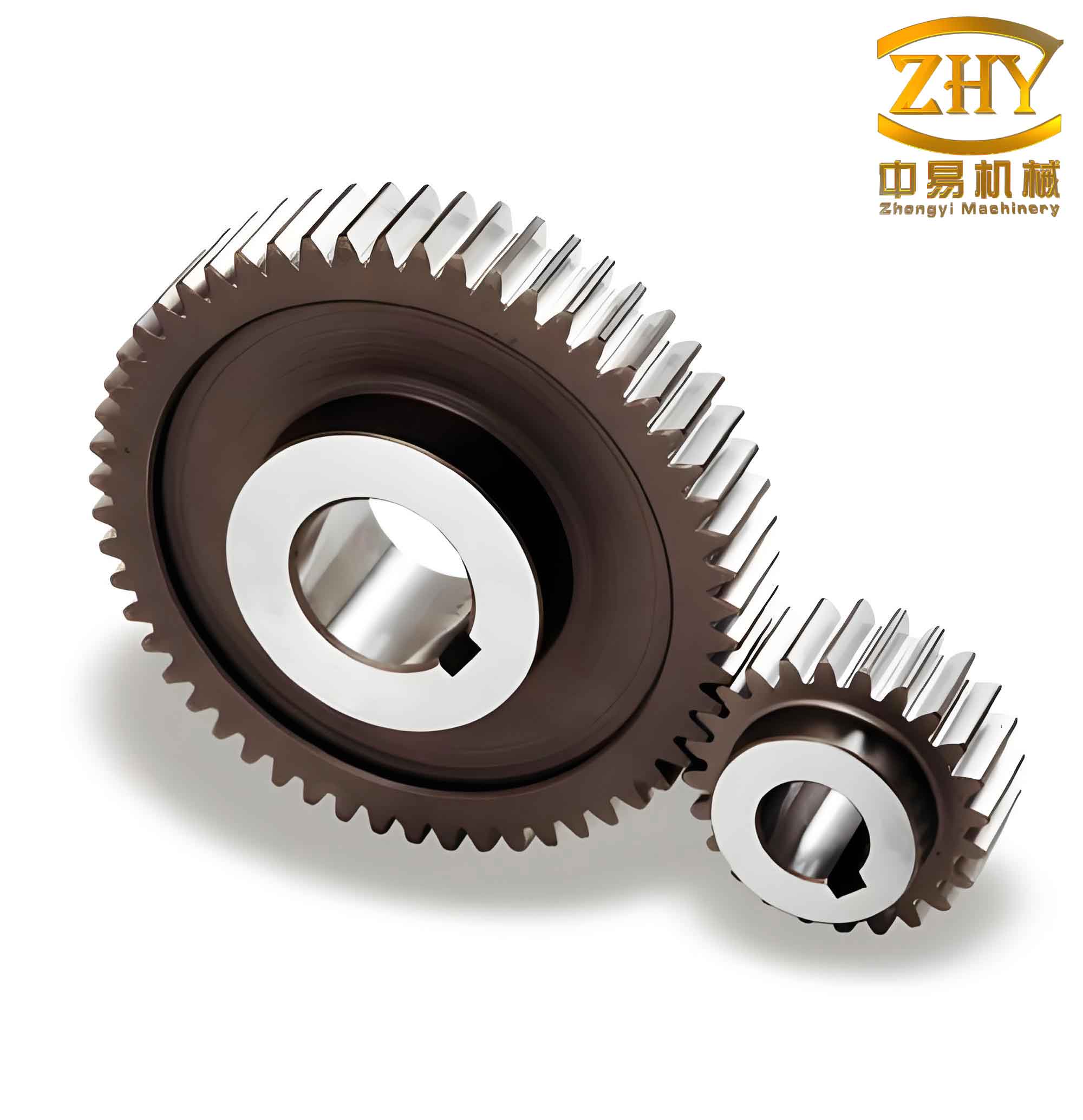
1. Numerical Model Setup
I selected a standard straight spur gear with parameters listed in Table 1. The material was AISI-1010 steel, which is commonly used in cold forging due to its good ductility. The die components (punch, container, and lower die) were treated as rigid bodies, while the workpiece was modeled as a plastic object. I applied a shear friction model with a friction factor of 0.12. Because the gear has 20 teeth and a module of 3 mm, I took advantage of symmetry and modeled only one quarter of the blank to reduce computational time. The blank outer diameter was chosen slightly smaller than the dedendum circle diameter of the die cavity to ensure proper placement and rapid tooth filling. The detailed blank dimensions are shown in Table 2. The punch speed was set to 10 mm/s. A tetrahedral mesh with automatic remeshing was used in Deform-3D.
| Parameter | Value |
|---|---|
| Material | AISI-1010 |
| Module (m) | 3 mm |
| Number of teeth (z) | 20 |
| Pressure angle (α) | 20° |
| Profile shift coefficient (x) | 0.0 |
| Parameter | Value |
|---|---|
| Outer diameter (Dblank) | 52 mm |
| Central hole diameter (dhole) | 16 mm |
| Blank height (h) | 37.5 mm |
2. Simulation Results and Discussion
2.1 Effective Stress Analysis
During the simulation, I monitored the effective stress distribution at three critical stages: early (step 30), intermediate (step 80), and final (end of stroke). At step 30, the material near the tooth cavity experienced high stress, while the central region remained relatively low. This indicates that deformation initially concentrated at the tooth areas, with material flowing radially outward from the blank center. At step 80, most teeth were already formed, and the highest stress appeared at the tooth root, where the material experienced maximum shear as it flowed into the die cavity. The central hole gradually closed, creating a free surface that helped reduce the forming load. At the final stage, the stress distribution became more uniform, ranging from 615 MPa to 673 MPa. The greatest stress was observed at the tooth tips where they contacted the die wall first. The hole was completely closed, and the gear teeth were fully filled without any defects.
Table 3 summarizes the effective stress values at different simulation steps for the straight spur gear.
| Step | Minimum Stress (MPa) | Maximum Stress (MPa) | Average Stress (MPa) |
|---|---|---|---|
| 30 | 120 | 820 | 470 |
| 80 | 350 | 950 | 610 |
| Final | 615 | 673 | 645 |
The effective stress distribution can also be described by the von Mises yield criterion. For the straight spur gear material, the flow stress can be expressed as:
$$ \bar{\sigma} = K \bar{\varepsilon}^n $$
where \( \bar{\sigma} \) is the effective stress, \( K \) is the strength coefficient (approximately 950 MPa for AISI-1010 at large strains), \( \bar{\varepsilon} \) is the effective strain, and \( n \) is the strain hardening exponent (about 0.22). This relationship explains why the stress increases significantly as the tooth cavity fills and the strain accumulates.
2.2 Effective Strain Analysis
The effective strain contours at different steps revealed the deformation history of the straight spur gear. At step 30, strain was concentrated in the tooth region, with the central area experiencing almost no plastic deformation. As the punch moved downward, the blank was forced into the tooth cavities. The upper and lower surfaces of the blank were in direct contact with the punch and the lower die, creating a constraint that hindered the filling of the tooth corners. This led to a “bulging” effect in the middle of the tooth height. At step 80, a large amount of material had accumulated in the middle of the teeth, but the top and bottom corners remained unfilled. The maximum strain occurred at the tooth root. In the final stage, the highest strain values were observed at the top and bottom corners of the teeth—these were the most difficult regions to fill and the last to be fully formed. The strain distribution correlated well with the stress distribution.
Table 4 lists the effective strain values for the straight spur gear at the three stages.
| Step | Minimum Strain | Maximum Strain | Average Strain |
|---|---|---|---|
| 30 | 0.05 | 0.80 | 0.35 |
| 80 | 0.30 | 1.80 | 0.95 |
| Final | 0.60 | 2.50 | 1.40 |
The effective strain can be related to the principal strains by:
$$ \bar{\varepsilon} = \sqrt{\frac{2}{3} \left( \varepsilon_1^2 + \varepsilon_2^2 + \varepsilon_3^2 \right)} $$
where \( \varepsilon_1, \varepsilon_2, \varepsilon_3 \) are the principal logarithmic strains. In the hole divided-flow forming of the straight spur gear, the radial and circumferential strains are dominant due to the outward flow of material into the die cavities.
2.3 Forming Load Analysis
The load-displacement curve is a key indicator of the forming characteristics of the straight spur gear during hole divided-flow forging. I recorded the punch force at every simulation step and plotted it against the punch travel. The curve showed three distinct phases:
- Phase I (0 – 10 mm travel): The load increased gradually from zero to about 1000 kN. During this stage, the material had a free surface at the central hole, which allowed easy flow and kept the forming force low.
- Phase II (10 – 18 mm travel): The load continued to rise but at a slightly higher rate. The tooth cavities were mostly filled, and the central hole began to shrink.
- Phase III (18 – 20 mm travel): In the final 2 mm of punch travel, the load increased sharply from about 1500 kN to a peak of 2200 kN. This steep rise occurred because the central hole had completely closed, leaving only the tooth corners unfilled. To fill these corners, the material had to overcome high triaxial compressive stress, requiring a drastic increase in load.
Table 5 presents the punch load at various displacements for the straight spur gear forming.
| Punch Displacement (mm) | Load (kN) | Description |
|---|---|---|
| 0 | 0 | Initial contact |
| 5 | 420 | Early tooth filling |
| 10 | 1000 | End of Phase I |
| 15 | 1350 | Mid-stage |
| 18 | 1500 | Beginning of Phase III |
| 19 | 1850 | Sharp rise |
| 20 | 2200 | Maximum load |
The load-displacement relationship can be approximated by a power law for the early stage:
$$ F = a \cdot s^b $$
where \( F \) is the punch load, \( s \) is the displacement, and \( a, b \) are constants determined by the material and geometry. For the straight spur gear in my simulation, \( a \approx 50 \) kN/mmb and \( b \approx 1.8 \) for the first 10 mm. However, at the final stage, the load increased exponentially due to the lack of free surfaces.
It is important to note that the maximum load of 2200 kN is significantly lower than what would be required for conventional closed-die forging of a straight spur gear without a central hole. In traditional forging, the load can exceed 3500 kN for the same gear dimensions. Thus, the hole divided-flow method offers a clear advantage in reducing the forming force.
3. Conclusion
Through my numerical simulation of the hole divided-flow forming process for a straight spur gear, I obtained the following key findings:
- As the punch moves downward, the tooth cavities gradually fill, and the central hole closes. The maximum effective stress and strain occur at the tooth root region during the intermediate stage and at the tooth corners during the final stage.
- The load-displacement curve exhibits a sharp increase in the last 2 mm of travel, corresponding to the final filling of the tooth corners. The overall maximum forming load is about 2200 kN, which is much lower than that of conventional forging methods.
- The simulated straight spur gear showed complete tooth filling with no defects. The grain flow would be continuous along the tooth profile, ensuring high load capacity.
- These results provide a valuable theoretical reference for the practical production of straight spur gears using hole divided-flow forging. The process can be optimized by adjusting the initial hole diameter, blank height, and friction conditions to further reduce the load and improve die life.
In conclusion, the hole divided-flow forming technique is a promising method for manufacturing high-quality straight spur gears with lower forming forces. My numerical analysis confirms its feasibility and offers guidelines for die design and process parameter selection.