
In the process of cylindrical gear form grinding, the tooth surface equation of the machined cylindrical gear can be determined according to the known axial section profile of the form grinding wheel, the relative position and relative motion of the wheel and the cylindrical gear workpiece. When grinding cylindrical gear, due to the installation error, the relative position between the grinding wheel and the workpiece will deviate from the ideal position, resulting in the deviation of the machined tooth surface. The relative position deviation of grinding wheel and cylindrical gear workpiece mainly includes eccentric error of grinding wheel axis deviating from ideal position, axial error of grinding wheel along its axis and inclination error of grinding wheel spindle deviating from ideal direction.
The eccentric error and axial error of grinding wheel are shown in Fig. 1. When the eccentric error exists between the grinding wheel and the cylindrical gear workpiece (see Fig. 6a), the offset of the grinding wheel center along the X2 axis on the grinding wheel plane is Δ SX, and the offset along the Y2 axis is Δ sy, and the grinding wheel center is shifted from O2 to O2 ‘. When there is axial deviation between the grinding wheel and the cylindrical gear workpiece (see Fig. 1b), the offset of the grinding wheel plane along the Z2 axis is Δ SZ, and the center of the grinding wheel moves from O2 to O2 ″ along the Z2 axis.

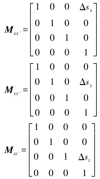
According to the transformation rules of spatial coordinate system, when the position deviation of grinding wheel relative to cylindrical gear workpiece exists in X2, Y2 and Z2 directions, the corresponding error transformation matrices mxx ‘, Myy’ and mzz ‘are as follows:
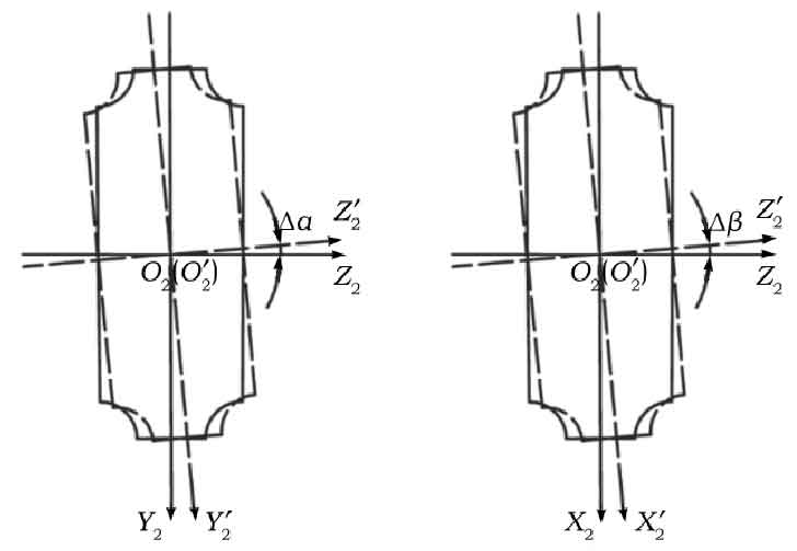
The inclination error of grinding wheel refers to the deviation of the angle between the axis of grinding wheel and the axis of parts to be machined from the design angle. The inclination error of grinding wheel is shown in Fig. 2. When the grinding wheel has tilt error, there are two cases, namely, the tilt error Δ α (see Fig. 2a) caused by the rotation of the grinding wheel axis around the X2 axis and the tilt error Δ β (see Fig. 2b) caused by the rotation of the grinding wheel axis around the Y2 axis.
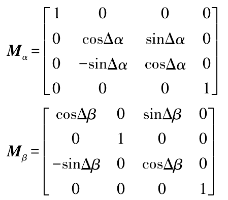
When the inclination errors Δ α and Δ β exist in the grinding wheel, the corresponding error conversion matrices m α and m β are as follows:
When the eccentric error and axial error occur, the center of the grinding wheel deviates from the ideal position, but the axis direction of the grinding wheel does not change; when the tilt error occurs, the axis direction of the grinding wheel changes, but the center of the grinding wheel does not change; Therefore, the eccentric error, axial error and tilt error of grinding wheel affect the machining accuracy of gear independently.
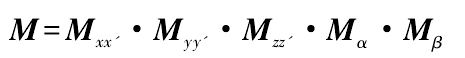
According to the above analysis and formula of the position deviation of grinding wheel, the error conversion matrix M of grinding wheel with position deviation can be obtained
According to the formula, the coordinate transformation equation of the actual contact line can be obtained when the grinding wheel has position deviation
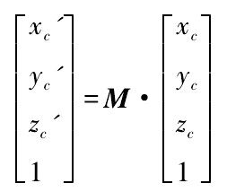
Where: XC ‘, YC’ and ZC ‘are the coordinate values of the actual contact line in the coordinate system o1-x1y1z1.
It can be obtained from the formula that the coordinate transformation equation on the actual tooth surface of the grinding wheel with position deviation is as follows:
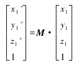
Where: X1 ‘, Y1’ and Z1 ‘are the coordinate values of the actual tooth surface in the coordinate system o1-x1y1z1.