
In my extensive experience with precision manufacturing, I have found that straight spur gears are among the most widely used mechanical components, found in everything from machine tools and aircraft to everyday appliances like watches and electric fans. The production of high-quality straight spur gears often requires efficient and flexible machining methods. While traditional gear cutting techniques such as hobbing and shaping are suitable for mass production, small-batch or prototype runs demand more adaptable approaches. This is where the combination of a CNC dividing head and macro programming proves invaluable. In this article, I will discuss how I apply macro programs to mill straight spur gears using a CNC dividing head on a vertical milling machine, emphasizing the parametric nature of the process and providing detailed mathematical formulations, tables, and program examples.
Macro programs represent a high-level programming technique in CNC machining that allows the use of variables, arithmetic operations, and conditional loops directly within the G-code. Instead of hardcoding each coordinate value, I can define variables such as #1, #2, etc., and compute tool paths dynamically. This approach drastically reduces the length of the program and enhances adaptability. For example, when milling straight spur gears, the only parameters that change from one gear to another are the number of teeth, module, pressure angle, and blank dimensions. With a macro program, I simply update these input values, and the machine automatically generates the correct tool path for each tooth space. This is far more efficient than rewriting the entire G-code for each new gear or relying on CAM software to regenerate lengthy post-processed files for minor modifications.
Macro Program Fundamentals for Gear Milling
Before diving into the specific application for straight spur gears, let me outline the basic structure of a macro program I use. In Fanuc-style controllers, variables are denoted by # followed by a number. For instance, #1 can represent the current tooth index, #2 the module, #3 the number of teeth, etc. A typical macro program contains a loop that iterates over each tooth space. Inside the loop, the dividing head (A-axis) rotates to the correct angular position, and the milling cutter executes the radial infeed and axial motion to cut the tooth profile. The key mathematical relationship is the angular indexing increment:
$$
\theta = \frac{360^\circ}{z}
$$
where \(z\) is the number of teeth on the straight spur gear. The dividing head must rotate by this amount after each tooth is cut. In the macro, I use a counter variable #1 that starts at 0 and increments until \(z-1\). At each iteration, the A-axis command is A[#1 * #angle], where #angle is the computed index angle.
To make the program truly parametric, I also include formulas for the tooth depth and the radial infeed. The total depth of cut for a standard involute straight spur gear is typically \(2.25 \times m\), where \(m\) is the module. However, in practical milling, I often cut in multiple passes to reduce tool load and improve surface finish. The macro can incorporate a nested loop for depth increments. Table 1 summarizes the primary variables I use in the macro program.
| Variable | Description | Example Value |
|---|---|---|
#1 |
Tooth index counter (0 to z-1) | 0, 1, 2, … 79 |
#2 |
Number of teeth (z) | 80 |
#3 |
Module (mm) | 2 |
#4 |
Pressure angle (degrees) | 20 |
#5 |
Index angle (360/z) | 4.5 |
#6 |
Total depth of cut (2.25*m) | 4.5 |
#7 |
Number of roughing passes | 2 |
#8 |
Finish allowance (mm) | 0.2 |
Process Analysis for Milling Straight Spur Gears
The milling of straight spur gears using a CNC dividing head follows a systematic procedure that I always adhere to. First, I inspect the gear blank, particularly the outside diameter, to verify it matches the design value. The outside diameter \(d_a\) for a standard straight spur gear is given by:
$$
d_a = m \cdot (z + 2)
$$
If the actual diameter deviates, I adjust the cutting depth accordingly to maintain the correct tooth thickness at the pitch circle. Next, I mount the blank. For shaft-type blanks, I clamp one end in the three-jaw chuck of the dividing head and support the other end with a tailstock center. For disk-type blanks, I first mount them on an arbor, then clamp the arbor between the dividing head and tailstock. It is critical to align the workpiece so that its axis is parallel to the X-axis of the milling machine table and at a constant height relative to the table surface. Misalignment will cause the teeth to be cut at an angle or with varying depth, resulting in a defective straight spur gear.
After setup, I perform index calculations. For a gear with \(z\) teeth, the required index angle is \(\theta = 360/z\). If the dividing head has a worm gear ratio of 40:1 (common in many dividing heads), one full turn of the crank corresponds to 9 degrees of spindle rotation. However, when using a CNC dividing head with a direct angular command, I simply program the A-axis to rotate to the absolute angle. For example, for \(z=80\), each increment is 4.5 degrees. In the macro, I compute:
$$
\#5 = 360 / \#2
$$
Then, within the loop, the command is G0 A[#1 * #5] (assuming absolute positioning mode). Table 2 shows index angles for common tooth counts.
| Number of teeth (z) | Index angle (degrees) |
|---|---|
| 20 | 18.000 |
| 40 | 9.000 |
| 60 | 6.000 |
| 80 | 4.500 |
| 100 | 3.600 |
Selecting the appropriate form cutter is another vital step. For straight spur gears with a given module and pressure angle, a set of 8 (or 15) involute cutters is available, each covering a range of tooth numbers. I must choose the cutter number that matches the actual tooth count of the gear. After mounting the cutter on the arbor, I check its rotation direction and ensure it runs true. I then perform a trial cut on the blank periphery to create a slight witness mark. This allows me to verify the indexing accuracy and detect any blank shift due to cutting forces. Only after confirming the setup do I proceed to adjust the cutting depth.
Cutting depth adjustment is based on the tooth thickness at the pitch circle. For a standard involute straight spur gear, the chordal tooth thickness \(s_c\) can be approximated by:
$$
s_c = m \cdot \left( \frac{\pi}{2} + 2x \tan \alpha \right)
$$
where \(x\) is the profile shift coefficient (zero for standard gears) and \(\alpha\) is the pressure angle. In practice, I use a gear tooth caliper to measure the tooth thickness after the first rough pass and fine-tune the radial infeed. For small module gears (\(m < 2.5\)), a single finishing pass is often sufficient. For larger modules, I program multiple roughing passes in the macro, reducing the depth incrementally. A typical macro structure for depth control includes an inner loop:
#10 = 0;  /* depth counter */
WHILE [#10 LT #7] DO1
  #11 = #6 / #7;  /* depth per pass */
  G01 Z-#11 F...;
  ... cut tooth profile ...
  #10 = #10 + 1;
END1;
Programming Example: Milling an 80-Tooth Straight Spur Gear
To illustrate the power of macro programming, I will present a concrete example: milling a straight spur gear with 80 teeth, module 2 mm, pressure angle 20°, using a CNC dividing head on a vertical machining center. The workpiece is mounted with its axis along the Y-axis of the machine, and the dividing head rotates around the Y-axis (A-axis). The cutter is a form milling tool positioned such that its centerline aligns with the X-axis of the machine. The zero point for the A-axis is set when the tooth space is centered under the cutter. The reference plane for Z is the top face of the blank, and X origin is at the left end face of the gear blank (optional). The following macro program (similar to the one referenced in the literature) performs the cutting:
O1699 (MACRO FOR STRAIGHT SPUR GEAR)
G54 G90 G00 X-10 Y-10 M3 S600
G43 H01 Z50.
#1 = 0   (TOOTH COUNTER)
#2 = 80  (NUMBER OF TEETH)
#3 = 2   (MODULE)
#5 = 360 / #2  (INDEX ANGLE = 4.5)
#6 = 2.25 * #3 (TOTAL DEPTH = 4.5)
WHILE [#1 LT #2] DO1
  G0 X-10 A[#1 * #5]   (POSITION TO TOOTH START)
  G1 Y-20 F200        (APPROACH)
  Z[0 - #6] F100      (CUT TO FULL DEPTH)
  X30                 (MILL ACROSS TOOTH SPACE)
  Y10                 (RETRACT)
  G0 Z50              (LIFT)
  #1 = #1 + 1         (NEXT TOOTH)
END1
G0 Z100
M5
M30
In this program, note that I use a single depth cut for simplicity (since module 2 is small). The cutter moves from X-10 to X30, which covers the full width of the tooth space. The Y motion (-20 to 10) ensures the cutter clears the blank on both sides. After each tooth, the A-axis rotates by 4.5 degrees to the next tooth position. If I needed multiple passes, I would embed an inner loop as described earlier. Table 3 details the variable values during execution.
| Tooth Index (#1) | A-axis position (degrees) | Cut depth (mm) |
|---|---|---|
| 0 | 0.000 | 4.5 |
| 1 | 4.500 | 4.5 |
| 2 | 9.000 | 4.5 |
| … | … | … |
| 79 | 355.500 | 4.5 |
One critical caution: when the number of teeth is not an exact divisor of 360, such as for a prime number like 81 teeth, the index angle becomes a repeating decimal (4.444…). In the macro, if I compute #5 = 360 / 81 and then use A[#1 * #5], the round-off error accumulates over many teeth, leading to significant angular error for the last tooth. To avoid this, I always use the exact fraction or increment in terms of the dividing head’s mechanical ration if possible. For a CNC dividing head with high-resolution encoders, I can program the angle directly as a floating-point number with sufficient digits, but I must ensure the controller does not accumulate truncation errors. A safer method is to compute the absolute angle for each tooth as #1 * 360 / #2 rather than incrementally adding a constant factor. For example:
WHILE [#1 LT #2] DO1
   #angle = #1 * 360 / #2
   G0 A[#angle]
   ...
   #1 = #1 + 1
END1
This guarantees that the final tooth is exactly at 359.9… degrees and the next tooth would return to 0 degrees without cumulative error.
Mathematical Formulation and Additional Formulas
The geometry of a straight spur gear involves several key parameters that I regularly compute using formulas. Beyond the simple index angle, the tooth profile requires careful consideration of the involute curve. However, when using form cutters, the cutting depth determines the tooth thickness. The following equations are essential for programming:
Outside diameter: \(d_a = m(z+2)\)
Root diameter: \(d_f = m(z-2.5)\)
Base diameter: \(d_b = m z \cos \alpha\)
Circular pitch: \(p = \pi m\)
Tooth thickness at pitch circle: \(s = \frac{\pi m}{2}\) (for standard gears with no profile shift)
The radial depth of cut \(h\) is the difference between the outside radius and the root radius, which is \(2.25m\). In my macro, I use this to set the Z-axis infeed. Table 4 summarizes these formulas for a module 2, 80-tooth gear.
| Parameter | Formula | Value (mm) |
|---|---|---|
| Outside diameter | \(m(z+2)\) | 164.0 |
| Pitch diameter | \(m z\) | 160.0 |
| Root diameter | \(m(z-2.5)\) | 155.0 |
| Circular pitch | \(\pi m\) | 6.283 |
| Tooth thickness | \(\pi m/2\) | 3.142 |
| Total depth | \(2.25 m\) | 4.5 |
When I need to adjust the cutting depth based on the actual outside diameter measured, I modify the total depth variable. For example, if the measured blank diameter is 163.8 mm instead of 164.0 mm, I add the difference to the depth so that the root diameter remains correct. The macro can include a correction factor #9 = (measured_OD - theoretical_OD) / 2 and then set #6 = 2.25*#3 + #9.
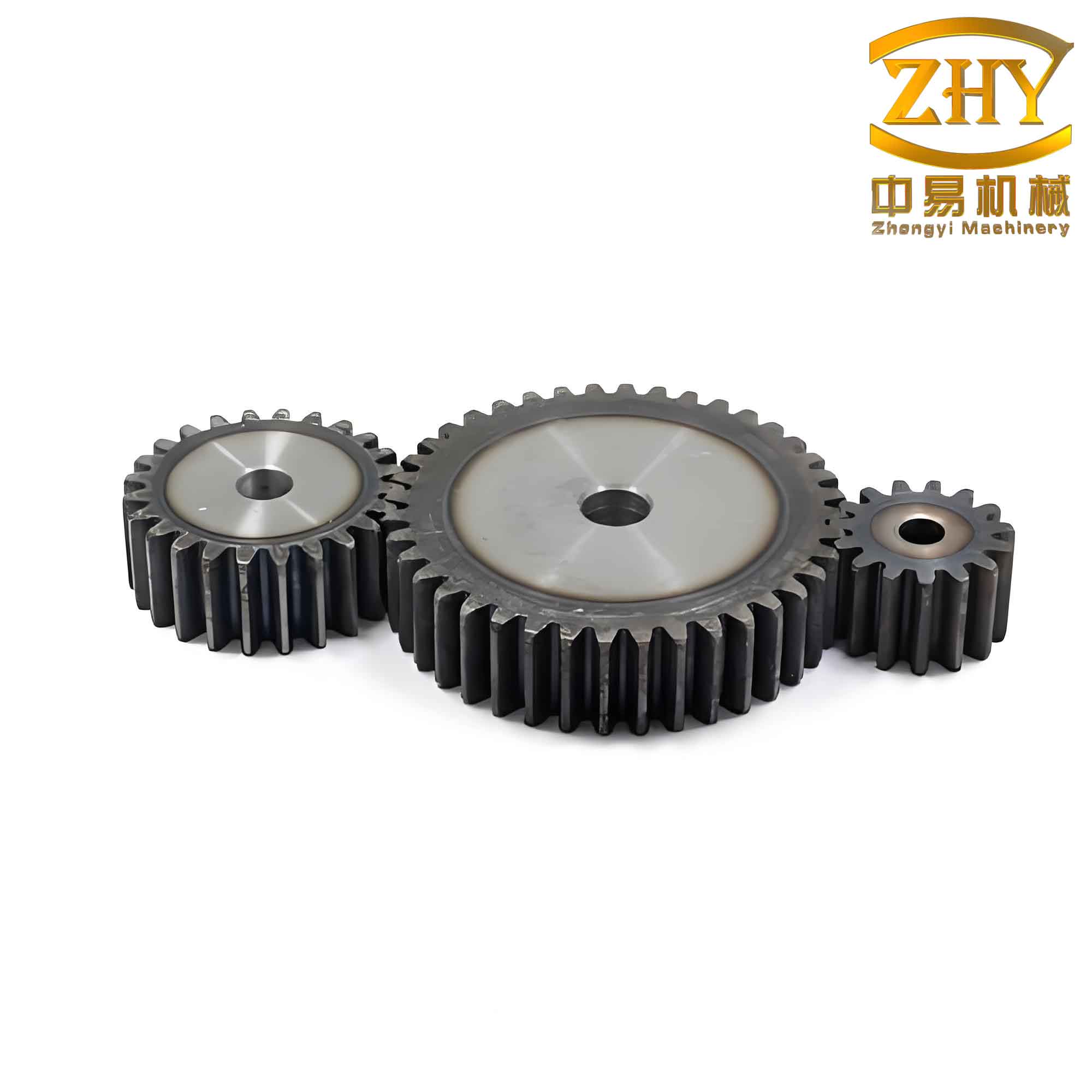
Integration of the Image
To further illustrate the concept, I have included a visual representation of a typical straight spur gear that can be machined using the described macro approach. The image below shows the gear profile and highlights the symmetry and spacing of the teeth, which are crucial for the indexing process.
Advanced Macro Features and Error Handling
In my practical machining of straight spur gears, I often incorporate additional features into the macro to improve reliability. For instance, I include a check for the number of teeth to ensure it is within the range of the available cutter. If the macro detects a tooth count outside the cutter’s range, it can issue an alarm or prompt the operator. I also add a subroutine to handle the approach and retract motions safely, avoiding collisions with the blank or fixture. The cutting parameters, such as spindle speed and feed rate, are also parameterized so that they can be optimized for different material (steel, aluminum, brass). Table 5 shows typical cutting parameters for common materials when milling straight spur gears with HSS form cutters.
| Material | Spindle Speed (RPM) | Feed Rate (mm/min) | Depth per Pass (mm) |
|---|---|---|---|
| Low-carbon steel | 300 – 500 | 50 – 100 | 0.5 – 1.0 |
| Alloy steel | 200 – 350 | 30 – 60 | 0.3 – 0.8 |
| Aluminum | 1000 – 2000 | 200 – 400 | 1.0 – 2.0 |
| Brass | 800 – 1200 | 150 – 300 | 0.8 – 1.5 |
Another important aspect is the measurement of tooth thickness after the first workpiece. I use the macro to output a variable that indicates the expected chordal thickness, which I then compare with actual measurements using a gear tooth micrometer. If the deviation exceeds tolerance, I adjust the depth offset in the macro and run a finish pass. This closed-loop approach ensures high precision for straight spur gears even when the blank dimensions vary.
Comparison with Automatic Programming
While CAM software can generate tool paths for straight spur gears, the macro programming approach offers distinct advantages when dealing with variations. For example, if I need to change the module from 2 to 2.5, I only modify the value of #3 in the macro. With CAM, I would have to redefine the entire gear geometry, regenerate the tool path, and post-process the code. This makes macro programs extremely efficient for job shops that frequently produce small batches of different straight spur gears. Moreover, the macro can be easily modified to incorporate chamfering or deburring passes, which are difficult to handle with standard CAM operations without custom post-processors.
I have also used macro programs to machine straight spur gears with a different number of teeth on the same blank (e.g., a stepped gear). By varying the loop boundaries and the index angle accordingly, I can cut two different tooth counts on the same workpiece without changing the program structure. This versatility is a hallmark of parametric programming.
Potential Issues and Solutions
Despite the benefits, I have encountered several issues when using macro programs for straight spur gears. One common problem is the accumulation of rounding errors in angle calculations, which I already addressed. Another issue is the tool path interference when the cutter is not properly aligned with the tooth space center. To mitigate this, I always perform a dry run with no material to verify the tool path. Additionally, I use a ‘safe distance’ approach: the cutter starts in a retracted position, moves to the correct angular position, then plunges radially to the depth before moving across the tooth space. This sequence is illustrated in the macro example.
If the gear has a large number of teeth (e.g., 120 or more), the index angle becomes very small (3 degrees or less). The macro must handle fractional degrees with high precision. In such cases, I set the controller’s angular resolution to 0.001° and use double-precision variables if available. The following formula is used to compute the exact angle for each tooth without cumulative error:
$$
\theta_k = \frac{360 \cdot k}{z} \quad \text{for } k = 0, 1, …, z-1
$$
This ensures that the final tooth returns to exactly 360° (or 0°) after the last increment.
Conclusion
Through extensive practice, I have demonstrated that macro programs provide a powerful and efficient method for CNC milling of straight spur gears. The ability to parameterize tooth count, module, depth, and indexing angle allows rapid adaptation to different gear specifications. The macro code is compact, easy to debug, and can be reused across multiple projects. By incorporating tables of key parameters and formulas, I have created a flexible framework that simplifies the entire machining process, from setup to completion. The use of a CNC dividing head with direct angular control eliminates the need for manual indexing plates and reduces setup time. As a result, this approach is ideal for prototyping, repair work, and small-batch production of straight spur gears. I encourage other machinists to adopt macro programming for gear milling, as it combines the precision of CNC with the adaptability of manual methods, ultimately delivering high-quality gears with minimal programming effort.
Moreover, the integration of mathematical formulas directly into the macro ensures that the cutting depths and positions are always accurate, regardless of variations in blank dimensions. The example of an 80-tooth straight spur gear illustrates how a simple loop can generate the entire tooth profile efficiently. With the addition of error-handling routines and adjustable cutting parameters, the macro becomes a robust solution for real-world manufacturing environments. I am confident that this technique will continue to play a vital role in the production of straight spur gears and other toothed components, especially in facilities that value flexibility and quick turnaround.