
In the context of modern intelligent manufacturing, the integration of information technology with traditional mechanical design is essential. I have focused on the three-dimensional (3D) modeling of helical gears, which are widely used in high-speed and heavy-load transmissions due to their smooth engagement and high load capacity. Based on my experience with four representative CAD software packages—Siemens NX, Dassault SolidWorks, Zhongwang 3D, and AutoCAD—I have summarized the key modeling techniques and characteristics for helical involute gears. This research provides technical guidance for tool selection in mechanical design and lays a foundation for developing gear defect detection systems in the new generation of information technology environment.
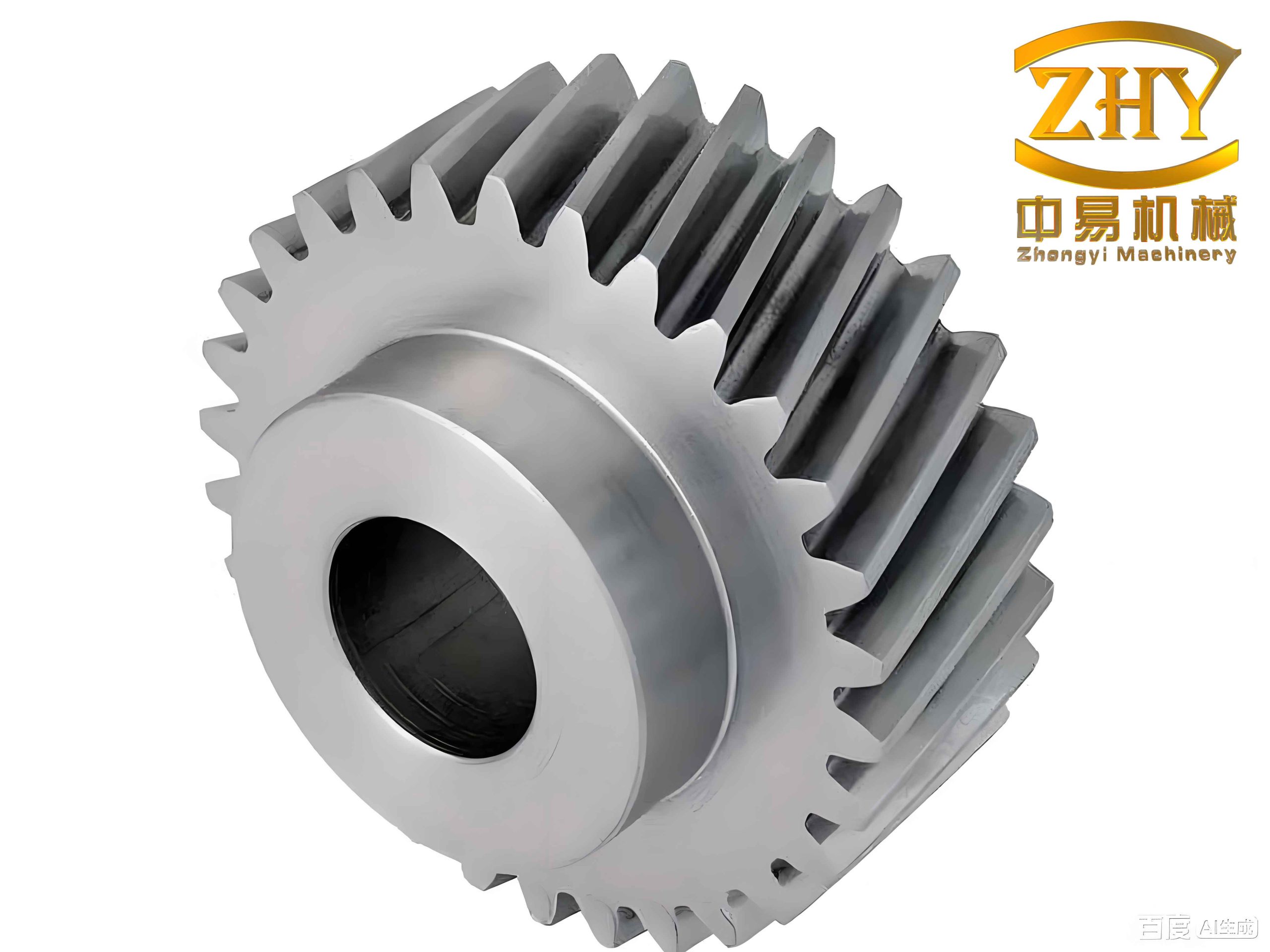
A helical gear is a disk-like part with a relatively large radial dimension. In my study, a specific helical cylindrical involute gear was designed with the following parameters: a hole diameter of 40 mm in the hub, a keyway width of 12 mm, a gear thickness of 35 mm, and two symmetrical recesses of 13.5 mm depth on the web for weight reduction. Six through holes of 17 mm diameter are evenly distributed on a pitch circle of 83 mm. The gear has 63 teeth with a normal module of 2 mm, a pressure angle of 20°, an addendum coefficient of 1, a clearance coefficient of 0.25, and a helix angle of 12° in the left-hand direction. The tip circle diameter is 132.815 mm, and the reference circle diameter is 128.815 mm. These geometric parameters are critical for accurate 3D modeling of the helical gear.
| Parameter | Symbol | Value |
|---|---|---|
| Number of teeth | Z | 63 |
| Normal module | mn | 2 mm |
| Normal pressure angle | α | 20° |
| Addendum coefficient | ha* | 1 |
| Clearance coefficient | c* | 0.25 |
| Helix angle | β | 12° (left-hand) |
| Face width | b | 35 mm |
| Tip circle diameter | da | 132.815 mm |
| Reference circle diameter | d | 128.815 mm |
I have employed several widely used CAD tools to construct the helical gear model. Each software offers distinct approaches, from specialized gear toolkits to equation-driven curve generation. Below, I detail the modeling procedure for each software individually.
Modeling with Siemens NX (UG)
In Siemens NX, two primary methods are available for modeling a helical gear: the GC Toolbox and the Expression method. The GC Toolbox is a specialized module developed for Chinese national standards. I selected the “Gear Modeling” option within the GC Toolbox, entered the normal module, number of teeth, face width, normal pressure angle, helix direction, and helix angle, and then clicked “OK” to generate the gear. This approach is straightforward and provides high precision comparable to other methods.
Alternatively, the Expression method offers more flexibility. I started by entering the gear parameters and the involute curve equations into the Expression Editor. The involute curve in the transverse plane is defined by:
$$x_t = r_b \cdot (\sin(t) – t \cdot \cos(t))$$
$$y_t = r_b \cdot (\cos(t) + t \cdot \sin(t))$$
where $r_b$ is the base circle radius. To align the tooth center with the coordinate axis, I rotated the curve by an angle $\theta$:
$$x_{t1} = x_t \cdot \cos(\theta) – y_t \cdot \sin(\theta)$$
$$y_{t1} = x_t \cdot \sin(\theta) + y_t \cdot \cos(\theta)$$
Using the “Law Curve” command, I created the involute profile. Then, in a sketch, I constructed the tip circle, reference circle, root circle, and base circle. The involute curve was mirrored and trimmed to form a single tooth profile. For the helical path, I created a helix using the expression:
$$z = \frac{b}{2\pi} \cdot \theta$$
where $b$ is the face width and $\theta$ is the angular parameter. Finally, I extruded the root circle to form a solid base, swept the tooth profile along the helix to create a single tooth, and used the “Array Feature” command to generate all 63 teeth. The result is a complete helical gear model.
Modeling with SolidWorks
SolidWorks provides an equation-driven curve tool that is ideal for parametric modeling of a helical gear. I first entered the gear parameters into the “Equations” tool. On the front plane, I sketched the gear blank with the hub, keyway, and recesses. Using the “Equation Driven Curve” with the parametric type, I input the rotated involute equations:
$$X_t = r_b \cdot \left( \sin(t + \text{Offset}) – t \cdot \cos(t + \text{Offset}) \right)$$
$$Y_t = r_b \cdot \left( \cos(t + \text{Offset}) + t \cdot \sin(t + \text{Offset}) \right)$$
I mirrored this curve to obtain the other side of the tooth flank, then used the “Trim Entities” command to define the tooth space (the area to be removed). Next, I created a helix on the reference circle by specifying the “Height and Pitch” method. The height equalled the face width of the helical gear, and the pitch was calculated from the helix angle:
$$\text{Pitch} = \frac{\pi \cdot d}{\tan(\beta)}$$
With the tooth space sketch and the helix, I performed a “Cut Sweep” to remove one tooth space from the gear blank. After applying a fillet to the tooth edges, I used the “Circular Pattern” command to replicate the cut across all 63 teeth, producing the final helical gear.
Modeling with Zhongwang 3D
Zhongwang 3D is a domestic CAD/CAM platform that supports both direct modeling and parametric curves. I began by creating the gear blank using standard extrusion and boolean operations. After sketching the basic geometry, I used the “Equation” command in the sketch environment. Among the available curve templates, I selected “Involute of Cylindrical Gear” and modified the parameters to match my helical gear:
$$X = \frac{m_n \cdot Z \cdot \cos\alpha}{2} \cdot \cos(60t) + \frac{\pi \cdot m_n \cdot Z \cdot \cos\alpha}{2 \cdot 60} \cdot \frac{t}{180} \cdot \sin(60t)$$
$$Y = \frac{m_n \cdot Z \cdot \cos\alpha}{2} \cdot \sin(60t) – \frac{\pi \cdot m_n \cdot Z \cdot \cos\alpha}{2 \cdot 60} \cdot \frac{t}{180} \cdot \cos(60t)$$
Here, $\alpha$ is the normal pressure angle, and $t$ is the parameter. I drew a line from the center to the intersection of the involute with the reference circle, rotated it by $90^\circ / Z$ to align the tooth center, and mirrored the involute to obtain the full tooth space. For the helix path, I chose the “Helical Spiral” option and entered:
$$X = \frac{m_n \cdot Z \cdot \cos\alpha}{2} \cdot \sin(12 \cdot 1 \cdot t)$$
$$Y = \frac{m_n \cdot Z \cdot \cos\alpha}{2} \cdot \cos(12 \cdot 1 \cdot t)$$
$$Z = 36 \cdot t$$
I then performed a “Sweep” operation with the tooth space as the profile and the helix as the path, generating a single solid tooth space. Using the “Array Feature” command with a polygon pattern of 63 instances, I subtracted all tooth spaces from the gear blank via boolean subtraction, resulting in the completed helical gear model.
Modeling with AutoCAD
AutoCAD is primarily a 2D drafting tool, but I used its 3D modeling workspace to construct the helical gear. Without built-in gear toolkits or parametric equation solvers, I relied on the geometric construction of the involute. I first drew the tip circle, reference circle, base circle, and root circle. Then I divided the base circle into n equal segments (n is a sufficiently large number, e.g., 60). From each division point, I drew a line perpendicular to the radius. On each perpendicular, I marked a point whose distance from the base circle equals the length of the arc from a fixed point to that division point along the base circle, multiplied by an integer multiple. This implements the involute generation principle:
$$l = r_b \cdot \phi$$
where $\phi$ is the angular increment. Using the “Spline” command, I connected these points to form one involute flank. I mirrored this curve by an angle of $2\pi / Z$ to obtain the other flank, then trimmed and arrayed the tooth profile. I extruded the entire planar profile to create a 3D solid. For the helix, I manually created a helical path using the “Helix” command with appropriate height and turns. Finally, a “Sweep” operation with the extrusion as the profile and the helix as the path, with a twist angle equal to the helix angle, yielded the final helical gear. Although the process is labor intensive, the model meets all geometric requirements.
Comparison of Modeling Methods
To provide a clear overview, I have compiled a comparison of the four software packages in terms of their nature, primary usage, modeling approach for the helical gear, and user experience.
| Software | Type | Primary Use | Helical Gear Modeling Method | User Experience |
|---|---|---|---|---|
| Siemens NX | High-end CAD/CAM | Complex surface modeling, NC programming | GC Toolbox; Expression-based involute + helix sweep | Powerful, dedicated gear module |
| SolidWorks | Mid-range 3D CAD | Mechanical design, assembly | Equation-driven curve for tooth space; cut sweep along helix | Intuitive, easy to learn, affordable |
| Zhongwang 3D | Domestic CAD/CAM | 3D design, simulation | Built-in involute equation; parametric helix sweep; boolean subtraction | Clean interface, good data exchange |
| AutoCAD | General drafting & basic 3D | 2D drawings, simple 3D | Geometric construction of involute; sweep with twist angle | Versatile for 2D, but less efficient for 3D |
From my hands-on experience, NX is the most efficient for helical gear modeling when using the GC Toolbox, requiring only parameter input. SolidWorks offers a smooth workflow with its equation-driven curve, making it suitable for designers who prefer parametric control. Zhongwang 3D provides a balanced environment with direct access to gear equations, while AutoCAD demands manual construction but offers excellent graphical control for custom shapes. All four packages can produce helical gear models that meet industrial tolerance requirements, but the choice depends on the designer’s specific needs and the complexity of the project.
Conclusion
In this study, I have systematically investigated the 3D modeling methods for helical involute gears using four popular CAD software tools: Siemens NX, SolidWorks, Zhongwang 3D, and AutoCAD. The modeling approaches range from specialized gear toolkits and parametric equations to geometric constructions based on the involute generation principle. A detailed comparison reveals that high-end and mid-range software like NX and SolidWorks provide greater automation and efficiency, while domestic software such as Zhongwang 3D offers intuitive interfaces and strong data interoperability. Although AutoCAD is less convenient for parametric gear design, its robust graphical engine remains valuable for custom geometry creation. The resulting helical gear models are accurate and ready for further analysis or integration into defect detection systems. This work serves as a practical guide for selecting the optimal CAD tool for helical gear design and contributes to the advancement of digital manufacturing technologies.