
The operation of the ball mill is achieved by meshing and rotating the small gear at the transmission end with the large gear on the cylinder. If there are design deviations, manufacturing defects, installation deviations, and poor operating environments in the gears of the ball mill, it may cause significant vibration during the operation of the ball mill, resulting in gear wear, contact fatigue, gear cracks, gear breakage, and other damage faults, affecting the safety, stability, and long-term operation of the ball mill.
1. 3D modeling
Taking a ball mill as an example, the gear parameters of ZHY Gear are shown in Table 1.
| Number of pinion gear teeth z1 | Number of wheel gear teeth z2 | Gear module m | Tooth width b | Spiral angle βi |
| 24 | 190 | 20 | 610mm | 5°15‘ |
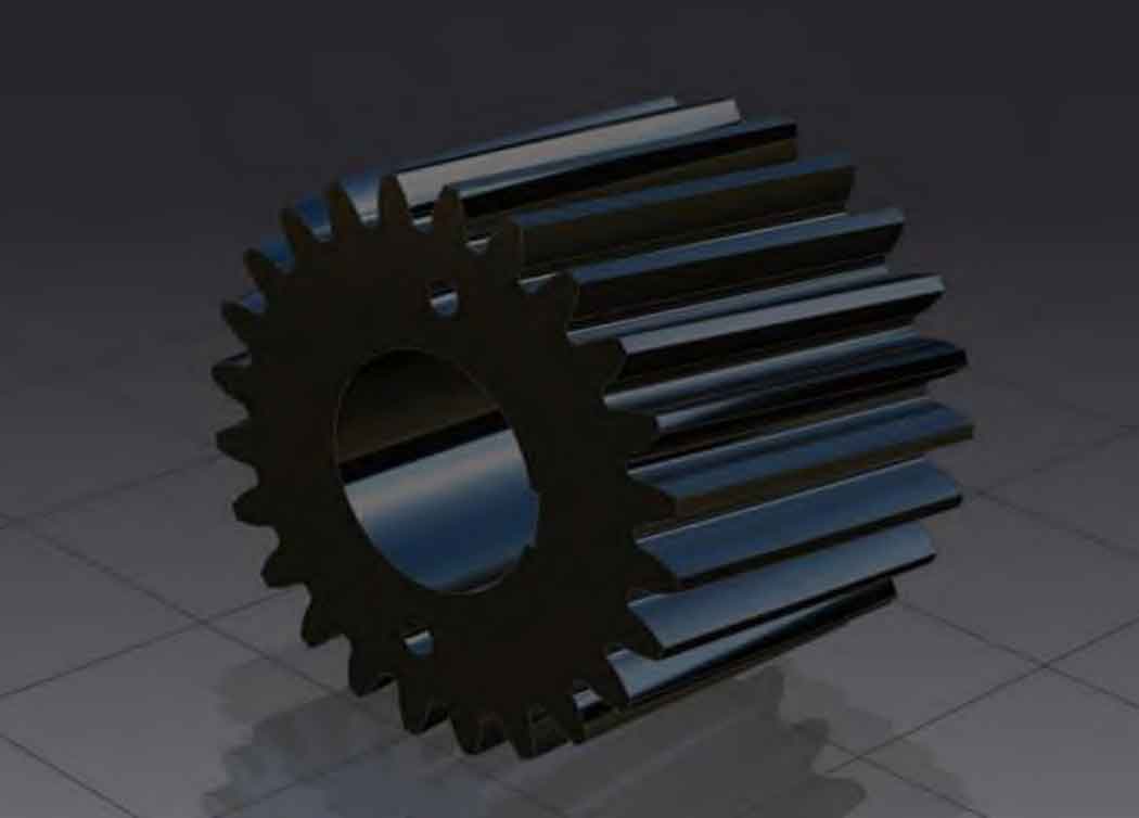
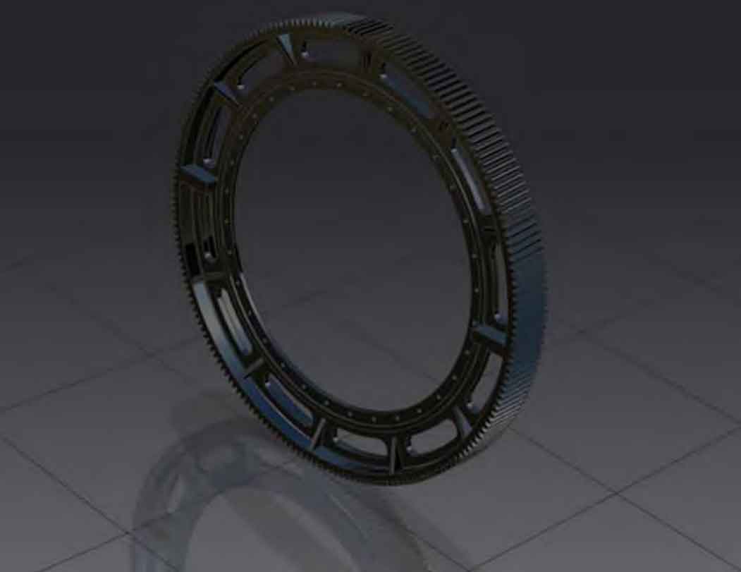
Using UG software for 3D modeling, draw the external geometric shape and mechanical structure of the small and large gears of the ball mill. The 3D models are shown in Figure 1 and Figure 2 on the following page.
2. Finite element analysis
Based on ANSYS software, perform dynamic modal analysis on the small and large gears of the ball mill, calculate the first six vibration modes to determine the maximum deformation position, and calculate the first six natural frequencies to avoid resonance.
2.1 Finite element analysis of small gears
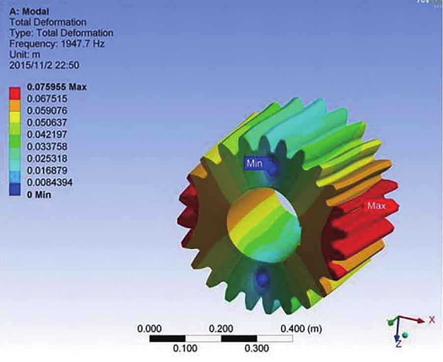
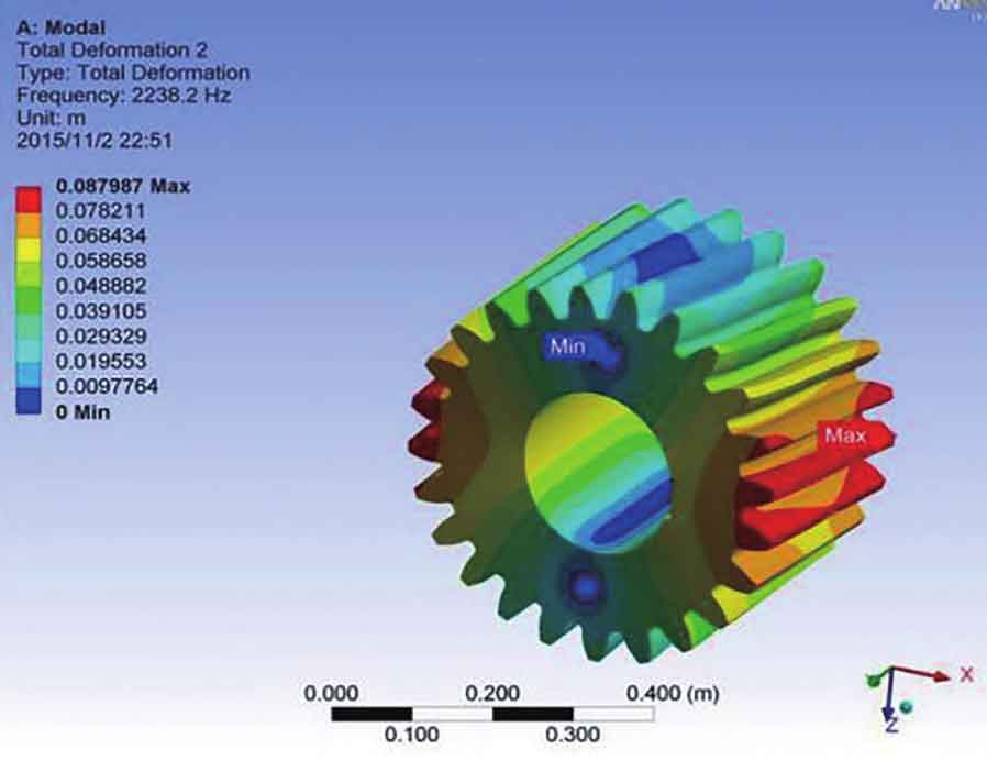
The first six vibration modes and natural frequencies of the small gear are shown in Figures 3 to 8.
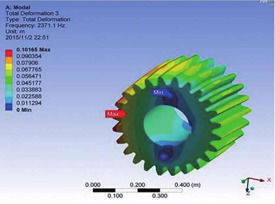
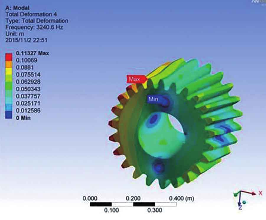
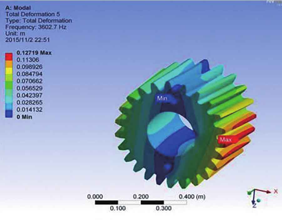
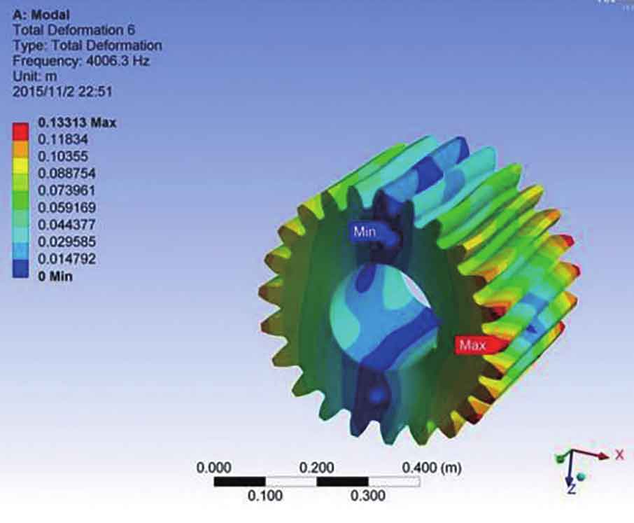
The summary of the first six natural frequencies of the small gear is shown in Table 2.
| Order | Natural frequency/Hz |
| First order | 1947.7 |
| Second order | 2238.2 |
| Third order | 2371.1 |
| Fourth order | 3240.6 |
| Fifth order | 3602.7 |
| Sixth order | 4006.3 |
2.2 Finite element analysis of large gears
The first six vibration modes and natural frequencies of the large gear are shown in Figures 9 to 14.
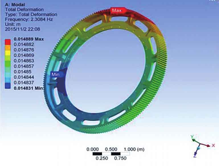
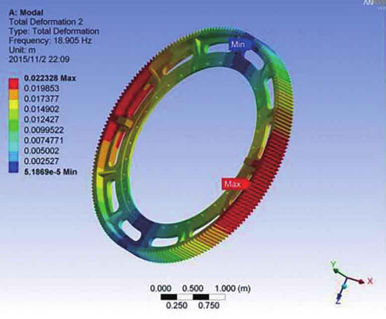
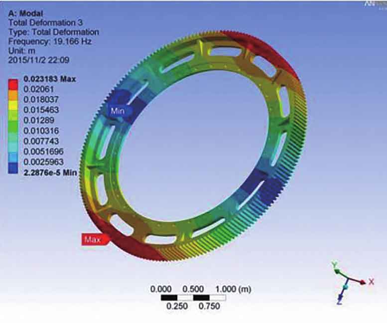
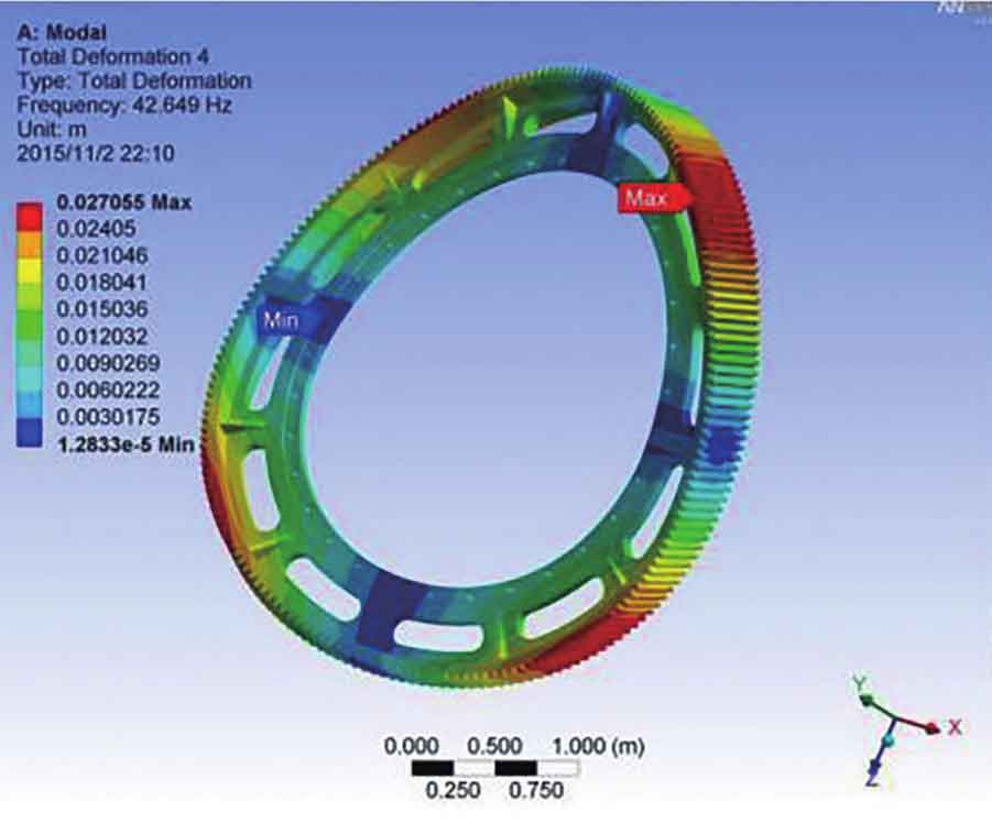
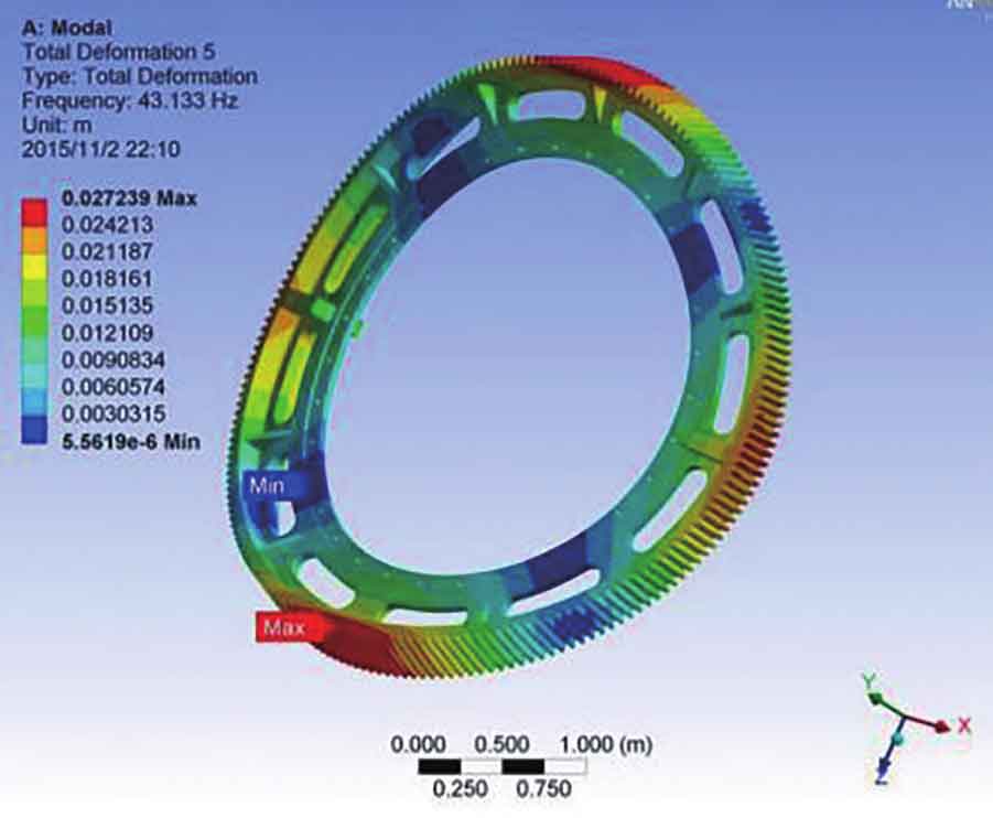
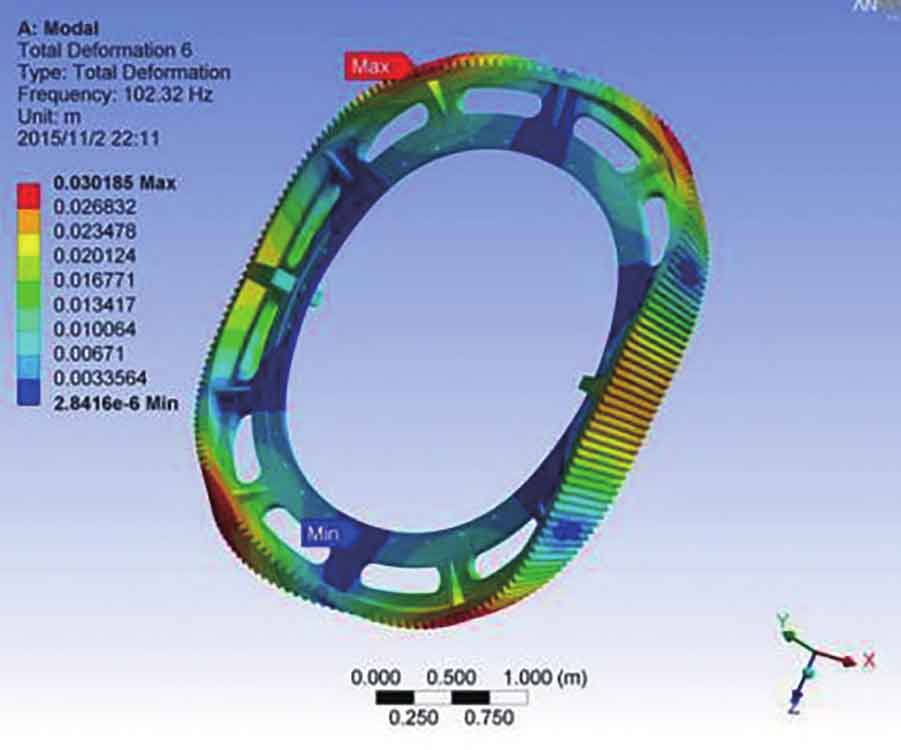
The summary of the first six natural frequencies of the large gear is shown in Table 3.
| Order | Natural frequency/Hz |
| First order | 2.3084 |
| Second order | 18.9050 |
| Third order | 19.166 |
| Fourth order | 42.649 |
| Fifth order | 43.133 |
| Sixth order | 102.32 |
2.3 Summary of Finite Element Analysis
The first six vibration modes and corresponding natural frequencies of the small gear and the large gear were obtained through finite element analysis. After calculation, the meshing frequency of the small gear and the large gear was 296Hz, so the two ball mill gears will not cause resonance due to the natural frequency and meshing frequency during operation. From the first six vibration mode diagrams of the small gear and the large gear, it can be seen that the teeth of the large gear are most prone to deformation.
3. Conclusion
During the operation of the ball mill, the large gear is absolutely limited by the small gear from the driving wheel. As the speed ratio is constant, it is a reduced speed transmission. Therefore, it is necessary to increase the speed of the small gear within an appropriate range to minimize the vibration frequency of the small gear and increase the vibration frequency of the large gear, in order to control the vibration frequency of the small gear and the large gear to be far away from their natural frequency. At the same time, it is necessary to strengthen regular inspections of the wear degree of the large gear teeth, strengthen maintenance, and collect and analyze real-time vibration signals of the ball mill.