
Bevel gears are critical components in various mechanical systems, and their manufacturing process requires careful planning and precise tooling to ensure high-quality production. This article explores the process specifications and tooling design for bevel gears, focusing on improving production efficiency and ensuring product quality.
Part Analysis
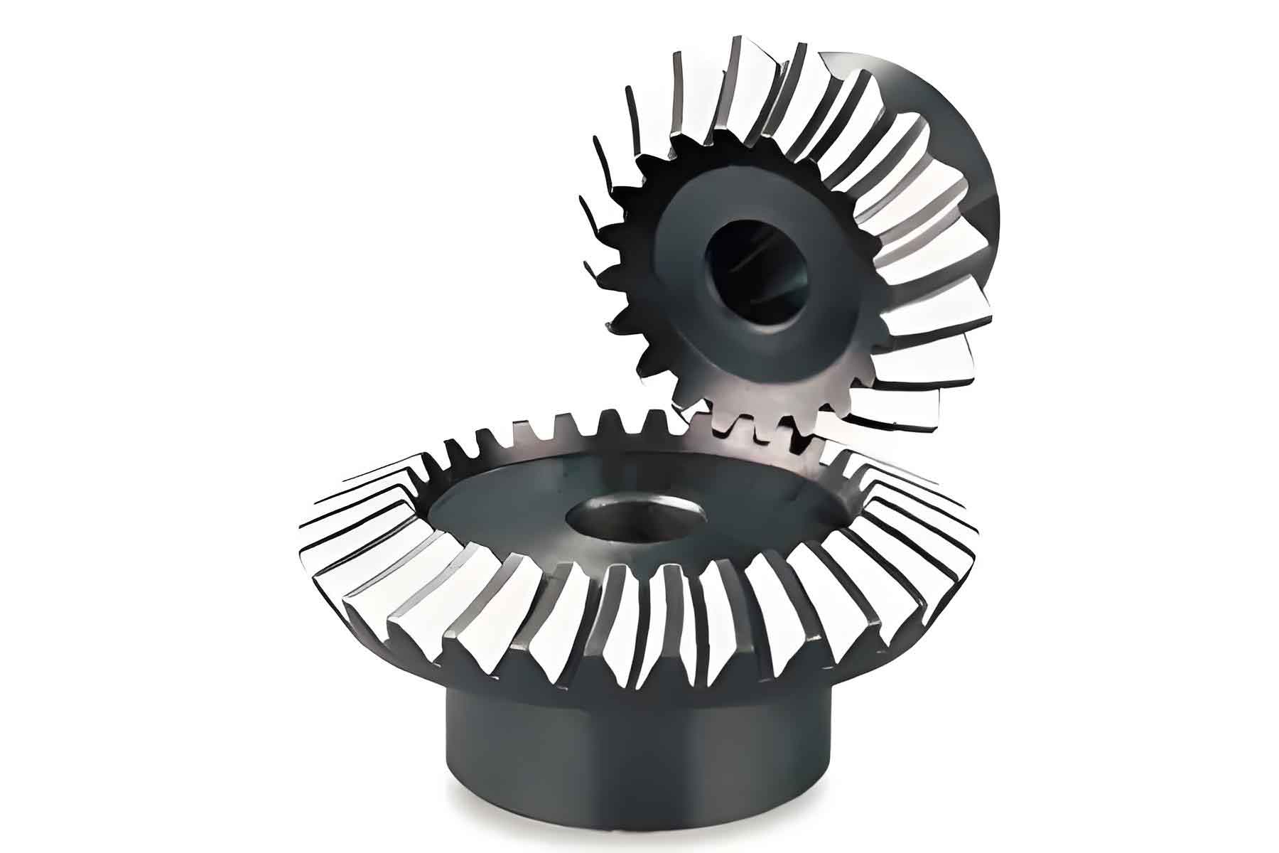
The bevel gear, a key part in the three-block lathe, is made of 45# medium carbon steel with a forged blank. After rough machining, it undergoes quenching and tempering treatment to enhance its strength, machinability, toughness, plasticity, and wear resistance.
For the selection of datum, the unprocessed surface should be chosen as the rough datum whenever possible. In the case of multiple unprocessed surfaces, the one with higher relative position accuracy to the processing requirements should be used. For gear milling or hobbing, the machined surface with a roughness of Ra6.3, the ɸ30 hole, and the keyway are used as the precision datum. The Ra6.3 end face restricts three degrees of freedom, the ɸ30 hole restricts two degrees of freedom, and the keyway restricts one degree of freedom.
The production type is determined to be medium-batch production, with an annual production volume of 1,200 pieces. Considering the complexity of the part, its high dimensional accuracy and geometric tolerance requirements, and the difficulty of achieving these using conventional processing methods, a process specification design is necessary.
Process Specification Design
The process specification for the bevel gear is designed as follows:
| Process | Workshop | Operation | Details |
|---|---|---|---|
| 1 | Production Department | External Processing | Forging the blank and normalizing treatment |
| 2 | Metalworking Workshop | Turning | Rough turning all parts with a 5 mm allowance, and using a large arc transition at the steps (C620 Horizontal Lathe) |
| 3 | Blade Branch | Heat Treatment | Quenching and tempering to HB240 – 280 (Box Furnace) |
| 4 | Metalworking Workshop | Turning | Rough turning the outer circle to ɸ112 by clamping the head (C620 Horizontal Lathe) |
| 5 | Metalworking Workshop | Turning | Clamping the head, aligning, turning the left end face, outer circle ɸ60, step surface, inner hole, and reverse turning the end face for alignment, and chamfering (C620 Horizontal Lathe) |
| 6 | Metalworking Workshop | Turning | Adjusting the clamping of the ɸ60 outer circle, aligning, and turning the right end to the specified dimensions, and chamfering (C620 Horizontal Lathe) |
| 7 | Metalworking Workshop | Slotting | Inserting the keyway (B5032 Slotting Machine) |
| 8 | Metalworking Workshop | Milling | Using the ɸ30 hole as the datum and the left end face as the positioning surface, forming the gear teeth (X53 Vertical Milling Machine) |
The design of the blank drawing for the part is also crucial. It provides a visual representation of the initial shape and dimensions of the material before processing.
Fixture Design
Two types of fixtures are designed for the manufacturing of bevel gears: the milling fixture and the hobbing fixture.
Bevel Gear Milling Fixture
The bevel gear milling fixture is designed for straight bevel gears with a modulus of 5 and 20 teeth. The rotation of the handle on the fixture drives the shaft system and the movable indexing plate, and the indexing of the workpiece is achieved using a pin. Forming milling cutters are used to mill the 20 tooth profiles of the bevel gear.
The structure of the fixture consists of several key components:
| Component | Description |
|---|---|
| Handle (ɸ12) | Used to rotate the shaft system and the movable indexing plate. |
| Plane Bearing 51100 | Provides smooth rotation. |
| Cover Plate | Helps to hold the components in place. |
| Bearings 61810 and 61809 | Support the rotation of the shaft. |
| Bearing Seat | The base component where other parts are assembled. It has precise holes for installing the bearings to ensure the dimensional and positional accuracy of the workpiece. The material is HT200 gray cast iron, which is annealed to ensure certain mechanical strength and vibration damping. |
| Static Indexing Plate | Used for indexing and positioning the workpiece. It has 20 – ɸ5H7 pin holes with specific tolerance requirements, and these holes are machined in one setup on the machining center to ensure accuracy. The material is 45# medium carbon quenched and tempered structural steel. |
| Movable Indexing Plate | Similar to the static indexing plate, it is used for indexing and positioning the workpiece and has the same pin hole requirements. |
| Connecting Sleeve | Used to connect the movable indexing plate, the main shaft, bolts, keys, and other parts. It has specific hole and keyway tolerances to ensure proper fits with other components. The material is HT200 gray cast iron. |
| Main Shaft | The key component of the fixture, which connects with the connecting sleeve, bolts, cover plate, keys, bearings, and the handle. It has various outer circle tolerances to ensure proper fits with other components, and the concentricity of these outer circles is required to be within 0.03 mm. The material is 45# medium carbon quenched and tempered structural steel. |
| Baffle | Used to fasten the workpiece and connects with the workpiece and bolts. The material is Q235A ordinary carbon steel for better economy. |
| Pin | The positioning part for workpiece indexing, which connects with the fixed and movable indexing plates. It has a ɸ5g6 outer circle tolerance and is in clearance fit with the holes in the indexing plates. The surface of the pin is ground and knurled. The material is 45# medium carbon quenched and tempered structural steel. |
| Cover Plate | The fastener of the fixture, which connects with the bearing seat, bolts, plane bearing, and other parts. The material is Q235 – A ordinary carbon steel. |
The working principle of the fixture is as follows: The fixture is placed on the workbench of the X53 Vertical Milling Machine, aligned using a gauge, and positioned using keys and clamped with a press plate. The workpiece is assembled on the fixture using the ɸ30 hole as the datum and the left end face as the positioning surface. By rotating the handle, the shaft system and the movable indexing plate are rotated, and the pin is inserted to achieve the indexing of the workpiece. The 20 tooth profiles of the bevel gear are then milled respectively.
Using this self – designed milling fixture, the tooth profiles of the bevel gear can meet the dimensional accuracy requirements of the drawings, ensuring consistency in batch production, solving the problem of low processing efficiency, and improving work efficiency and various performance indicators of the product.
Bevel Gear Hobbing Fixture
The bevel gear hobbing fixture is designed for straight bevel gears with a modulus of 5 and 20 teeth. The rotation of the workbench on the hobbing machine drives the fixture and the workpiece to rotate, and the hobbing cutter and the workpiece perform a generating motion to hob the 20 tooth profiles.
The structure of the fixture includes several main components:
| Component | Description |
|---|---|
| Cover Plate | The fastener for the workpiece, which connects with the mandrel, workpiece, and nut. The material is Q235 – A ordinary carbon steel. |
| Mandrel | It is both the positioning part for the fixture and the machine tool, and also the positioning part for the workpiece and the fixture. It has a ɸ30g6 outer circle tolerance and is in clearance fit with the holes in the workpiece and the sleeve. The surface roughness of the ɸ30g6 outer circle and the 1:10 taper surface is Ra1.6, and the radial runout is 0.01 mm. The material is 45# medium carbon quenched and tempered structural steel. |
| Sleeve | The axial positioning part for the workpiece, which connects with the mandrel, workbench, and workpiece. It has a ɸ30H7 inner hole tolerance and is in clearance fit with the mandrel. The surface roughness of the inner hole ɸ30H7 is Ra3.2, and the processing is done by grinding. The material is 45# medium carbon quenched and tempered structural steel. |
| Workbench | The base part for connecting the mandrel, sleeve, and other parts. The material is HT200 gray cast iron, which is annealed to ensure there are no casting defects such as pores and shrinkage, and to ensure certain mechanical strength and vibration damping. |
The working principle of the fixture is as follows: The mandrel and sleeve are assembled on the workbench of the hobbing machine, the workpiece is assembled on the mandrel, one end face of the workpiece contacts the sleeve, the cover plate is pressed on the workpiece, and the workpiece is clamped with a nut to make the conical surface of the mandrel fit with the conical hole of the workbench. The generating motion between the hobbing cutter and the workpiece is used to machine the tooth profiles of the bevel gear.
Using this self – designed hobbing fixture, the tooth profiles of the bevel gear can meet the dimensional accuracy requirements of the drawings, ensuring consistency in batch production, solving the problem of low processing efficiency, and improving work efficiency and various performance indicators of the product.
Conclusion
Through part analysis, process specification design, and fixture design, it has been proven in production that not only the machining accuracy of the bevel gear is improved, but also the labor intensity of the operators is reduced, the production cycle is shortened, and the productivity is greatly improved, ensuring the product quality.
In summary, the manufacturing of bevel gears requires a comprehensive understanding of the part’s requirements, careful selection of processing methods and tooling, and strict control of the production process. By continuously optimizing the process and improving the tooling design, we can achieve higher production efficiency, better product quality, and meet the diverse needs of various industries. The development of advanced manufacturing technologies and the application of precision tooling will continue to drive the progress and innovation in the field of bevel gear manufacturing.