

According to the schematic diagram of pitting section in Figure 1, the section at the node is selected to study and analyze the influence of different pitting characteristics and pitting positions on the section area and moment of inertia. The standard involute profile of the basic parameters (module 6.5mm, gear 24 and pressure angle 20 °) of the pinion of gear pair 1 is selected as the research and analysis object, and the calculation equation of the geometric characteristics and position parameters of the pitting pits is derived according to the above section. In order to study the independent influence of various factors on the characteristics of pitting pits, firstly, the rectangular shape of pitting pits is selected to be symmetrical about the y-axis in the YOZ plane, where LS + WS / 2 = L / 2 exists. The simulation results are shown in Figure 2. The curve drawn in Fig. 2 (a) shows that the cross-sectional area decreases with the increase of pit depth at the same pit width WS, and the deeper the pit depth is, the more obvious the reduction of cross-sectional area is; at the same pit depth HS, the cross-sectional area decreases with the increase of pit width, and the wider the pit width is, the more obvious the reduction of area product is. The change of section moment of inertia in Fig. 2 (b) is consistent with that in Fig. 2 (a), and decreases with the increase of width and depth.


The influence of pitting location on cross-section area and cross-section moment of inertia is studied under the fixed value of pitting geometric size (HS = 1 mm, WS = 5 mm). The simulation results are shown in Figure 3. It can be seen from the figure that the cross-section area and the cross-section moment of inertia are consistent with the change of the pitting position, and are invariable with the change of the pitting position, which indicates that the cross-section area and the cross-section moment of inertia do not change with the change of the pitting position from the perspective of mathematical simulation. It can be seen from the formula that the calculation expression of cross-section area is only related to the geometric characteristic parameters of pitting (depth HS, width WS), but has nothing to do with the location parameter ls of pitting. Similarly, it can be seen from the formula that the cross-section moment of inertia A is related to the distance of the centroid along the y-axis, while the change of the pitting position parameter LS changes the distance of the centroid of the pitting pit along the z-axis. It can be seen that the change of LS has no effect on the cross-section moment of inertia IZ, thus explaining that the cross-section area product and the cross-section moment of inertia shown in Fig. 3 remain unchanged.


According to the description of the causes of pitting and the pitting characteristic diagram shown in Fig. 4, pitting is easy to occur on the lower side near the pitch line. The basic parameters of gear pair 1 are still selected to further analyze the changes of cross-sectional area and moment of inertia of the region from the tooth root of involute profile to the pitch line. Since the location of pitting has no effect on the cross-sectional area and moment of inertia, the location of pitting along the tooth width is not considered in the analysis. Figure 5 shows the change of cross-sectional area and moment of inertia curve with the change of meshing angle under different pitting depth. In Fig. 5 (a), it can be seen that with the increase of pit depth, the cross-sectional area decreases under the same pit width, and the cross-sectional area also decreases along the tooth root pitch line. The moment of inertia of the cross section plotted in Fig. 5 (b) has the same effect on the pitting depth. The influence of different pitting width on cross-sectional area and moment of inertia is shown in Fig. 6. The change form of the curve in Fig. 6 is similar to that in Fig. 5, which shows a decreasing trend.


Combined with the meshing process of gear pair and the action interval of single double alternate meshing analyzed in Fig. 7, the CP segment in the single meshing interval is selected to set the pitting characteristics, and the geometric characteristics of pitting pits are simulated to study the influence on meshing stiffness. Firstly, the influence of pitting on tooth stiffness and contact stiffness under the formula derivation is studied, and the simulation results are shown in Figure 8. The axial compression stiffness curves drawn in Fig. 8 (a) without pitting and pitting characteristics can not directly show its variation characteristics, so the stiffness difference curve is further drawn. The stiffness difference curve shows that the stiffness difference is 0 in the non pitting area 52C, that is, the stiffness does not change; in the simulated pitting area CP, the stiffness difference gradually increases, and the stiffness difference increases in the non pitting area 52C After the simulated pitting position is exceeded, the stiffness difference decreases gradually from the peak value in Section D without pitting characteristics. It can be seen from the variation of the whole stiffness difference curve that the stiffness begins to decrease in the pitting region and reaches the peak value at the end of the pitting. Similar to Fig. 8, the influence of the center point shear stiffness on the change of the tooth stiffness is the same. There is a slight difference among the bending stiffness, compression stiffness and shear stiffness of the gear teeth shown in Fig. 8 (c). The main difference is that the stiffness difference curve of the Po section after pitting decreases rapidly, then increases and then decreases. The main reason may be that the calculation of the bending stiffness is related to the load components of the x-axis and: F-axis at the same time It is caused by different specific gravity. Fig. 8 (d) shows the change of the characteristic contact stiffness curve of pitting under the Yang sun model. The change of the stiffness curve shows that the contact stiffness decreases in the pitting area. The above analysis shows that the gear tooth surface pitting can reduce the tooth stiffness and contact stiffness.
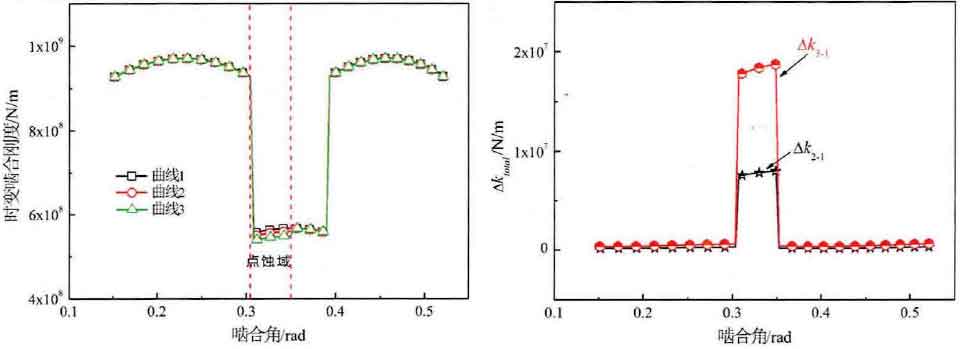

The influence of pitting geometry on the time-varying meshing stiffness is further studied. The simulation results are shown in Fig. 9 and FIG. 10. In order to explain the phenomenon characteristics conveniently, the definition of the stiffness curve name in the diagram is defined. Curve 1 indicates that there is no pitting on the tooth surface, while curve 2-4 respectively simulate the feature sizes of different pitting depth and width. The change of stiffness curve in Fig. 9 (a) shows that the stiffness in the simulated pitting area decreases obviously with the increase of pitting pit width, while the difference between curve 3 and curve 2 and curve 1 in Fig. 9 (b) shows that the stiffness change in the pitting area is more obvious than that in other meshing points. In FIG. 10, the effect of pitting depth on meshing stiffness is the same as that of pitting width, that is, the effect is more obvious in pitting area, but the change of stiffness is less obvious outside pitting area. In order to intuitively show the change of stiffness in the pitting area, the average stiffness of mesh stiffness in the pitting area is still selected for comparison. It is found that the stiffness reduction percentages of curve 2, curve 3 and curve 4 under different pitting characteristics are 1.39%, 3.25% and 1.38% respectively compared with curve 1. The above research and analysis data show that the time-varying meshing stiffness of the gear will be reduced when the pitting occurs, and the stiffness reduction value in the pitting area is more obvious than that in the non pitting area.