Introduction
Bevel gears are key components in gear transmission systems and are widely used in automotive, precision machine tools, aerospace, and other fields. Time-varying meshing Stiffness is an important basis for evaluating the performance of bevel gear transmissions, and accurately calculating its time-varying meshing stiffness is essential to ensuring the stability of the performance of bevel gear transmissions Therefore, it is of great significance to efficiently and accurately calculate the time-varying meshing stiffness of bevel gears. Scholars at home and abroad have conducted a lot of research on the calculation of the time-varying meshing stiffness of gears. Among them, there are many studies on cylindrical gears, and the calculation problem of their meshing stiffness has been basically solved. However, there is less research on the time-varying meshing stiffness of spatial bevel gears, and most scholars use finite element method to calculate it. Using finite element method Methods: This paper analyzes the tooth deformation and instantaneous meshing stiffness of straight bevel gears with multiple teeth engaged simultaneously. A finite element contact analysis model of straight bevel gear tooth pair meshing is established using finite element software to analyze the quasi-static meshing state of the gear pair. In addition, some scholars use traditional analytical methods for calculation. A method for calculating the load and stress of straight bevel gear teeth is proposed, and the accuracy of the method is verified through experiments. Based on energy equivalence, a meshing stiffness model of micro-segmented straight bevel gear teeth is established, and the single tooth meshing stiffness is calculated using integration methods. Although finite element method has high computational accuracy, it takes long time and its computational efficiency is limited by many factors; although traditional analytical calculation method takes short time, it cannot consider the coupling effect between tooth pairs, which leads to large errors in calculating multi-tooth meshing stiffness. In view of the above problems, this paper combines the advantages of finite element method and analytical method to propose a slice calculation method of straight bevel gear meshing stiffness considering the coupling effect between tooth pairs. The meshing stiffness, angular displacement of each slice center point, and load distribution of straight bevel gears under assembly errors are calculated and analyzed, and compared with the results of finite element calculation to verify the accuracy of the method proposed in this paper.
straight bevel gear slices
The three-dimensional structure and spatial meshing characteristics of spur bevel gears are characterized by discretizing the teeth of the bevel gear along the tooth width direction using a back cone, and discretizing the wheel body along the axis direction using a circular plane, resulting in a series of thin bevel gears with equal tooth widths. Based on the back cone equivalence principle, the large end back cone of each thin bevel gear is expanded. When the thin width is sufficiently small, the bevel gear is equivalent to a series of straight-tooth cylindrical gear teeth with the same number of teeth (but different sizes) meshing.
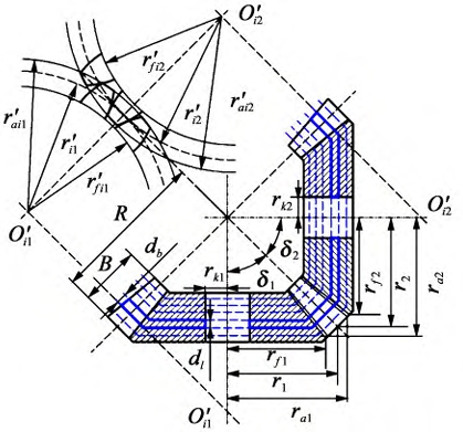
The teeth of the bevel gear are divided into a series of thin teeth with sufficiently small widths along the tooth width direction, where db is the width of the thin teeth; rj, rfj and raj (j=1,2, respectively for the driving gear and the driven gear, the same below) are the radii of the pitch circle, the addendum circle, and the dedendum circle of the bevel gear; δj, B, R, and rkj are the conic angle, tooth width, external cone pitch, and shaft hole radius of the bevel gear.
Each lamella can be approximated as a spur gear, and a spur bevel gear can be approximated as several spur gears in parallel. The stiffness of each lamella engaged at each instant is calculated, and the total meshing stiffness at each meshing position is obtained by summation. Under external load, the equivalent meshing stiffness of the gear caused by tooth deformation includes Hertzian contact stiffness, bending stiffness, shear stiffness, and radial compression stiffness. In addition, there is also the equivalent meshing stiffness of the gear caused by wheel body deformation, which is the wheel body stiffness.
The three-dimensional space structure of the bevel gear is established in the finite element software Ansys, where a three-dimensional finite element model of each sheet bevel gear is created. The figure shows the finite element model of the sheet i of the bevel gear.
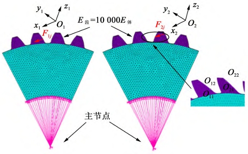
The displacement along the line of action induced by the gear wheel body at the meshing point is set to be 10,000 times the elastic modulus of the conical gear thin-film tooth. At this point, compared to the wheel body, the tooth can be considered as a relatively rigid region, thus allowing the displacement caused by local Hertzian contact and elastic deformation of the tooth to be neglected.
Deviation of each thin tooth profile caused by the assembly error of bevel gear
There are many factors that affect the meshing stiffness of straight bevel gears, in addition to design deviations and manufacturing errors, installation errors have a significant impact on the meshing stiffness of straight bevel gears. Therefore, only the deviation of tooth profile caused by installation errors (flake back cone error tooth profile) is considered in this article, and its meshing stiffness model is established. According to national standards, installation errors can be divided into axial intersection angle errors and axial intersection point errors.
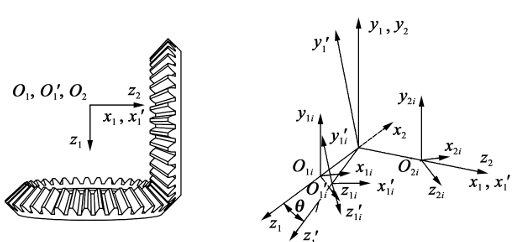
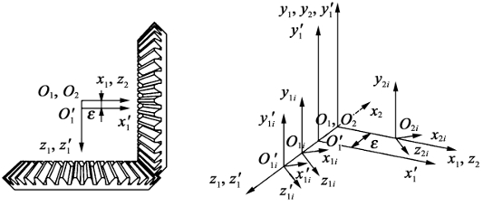
model of meshing stiffness of error tooth profile bevel gear
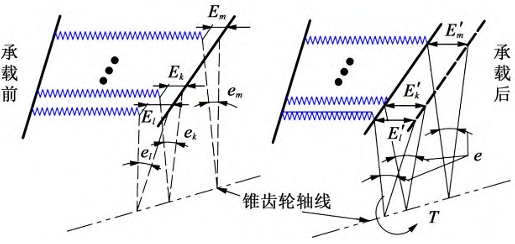
The axis of the bevel gear will shift and deflect, making each tooth pair involved in the meshing situation different, often resulting in edge contact and seriously affecting the transmission performance of the gear. Therefore, the calculation of the meshing stiffness under error conditions requires determining whether each tooth pair is involved in the meshing. Under the action of load, as the driving wheel rotates, the rotation angle deviation of the first contact tooth pair must be the smallest among all the teeth. Assuming that the rotation angle deviation em of tooth m is the smallest among all the teeth, that is, tooth m is the first to start contact. As the driving wheel continues to rotate, tooth m begins to deform elastically, causing a angular displacement θm at its center point. When the sum of θm and rotation angle deviation em is greater than the rotation angle deviation ek of tooth k, tooth k begins to contact and deform, taking on load; if at this time the load capacity does not meet the load capacity of the bevel gear, θm will continue to increase until the sum of θm and em is greater than the rotation angle deviation el of tooth pair l, when tooth pair l begins to engage. By analogy, until the load capacity of all participating tooth pairs equals the external torque T experienced by the bevel gear, the gear is in a state of force balance and deformation ends.
Finite element model of straight bevel gear
Finite element model of straight bevel gear. A mass21 element is established at the midpoint of the tooth width of the main and driven gear axes, coupled with the nodes on the inner surface of the gear wheel body. The axial rotational freedom of the driving gear is retained and a torque T=100 N·m is applied. The driven gear is subjected to full degree of freedom constraints. The normal penalty stiffness coefficient is set to 1 and the penetration coefficient is set to 0.1. The augmented Lagrangian method is used for solving.
Verification of meshing stiffness of straight bevel gear
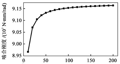
During the meshing cycle, when the rolling angle is 0°, that is, when the straight bevel gear just enters the double-tooth meshing, the mesh independence is based on the meshing stiffness As shown in the figure, the convergence of this method is good, and the meshing stiffness value tends to stabilize when the number of blades is greater than 60.
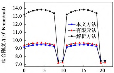
When the number of selected flakes is 60, the comparison of the results of the direct-tooth bevel gear meshing stiffness calculation using the proposed method, traditional analytical method, and finite element method is shown in the figure. From the figure, it can be seen that the analytical method has a large error in calculating the double-tooth meshing stiffness of the direct-tooth bevel gear, which is about 40%. The single-tooth and double-tooth meshing regions calculated by the proposed method are basically consistent with those of the finite element method, and the calculated results are also relatively close. The error of the double-tooth meshing stiffness is about 2%, and the error of the single-tooth meshing stiffness is about 3%. This indicates that the proposed method can accurately calculate the meshing stiffness of the bevel gear pair. The comparison of the calculation time between the analytical method and finite element method is shown. It can be seen that under similar calculation accuracy, the calculation time (including the time to calculate the wheel body stiffness correction factor) of the proposed method is much smaller than that of the finite element method, which is about 0.3% of the calculation time of the finite element method. In addition, the accuracy of the double-tooth meshing stiffness calculated by the proposed method is much higher than that of the analytical method, which is about 95% higher. In summary, it shows that the proposed method can quickly and accurately calculate the meshing stiffness of bevel gears.
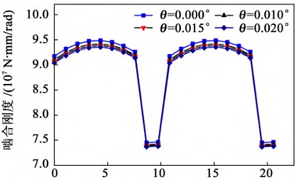
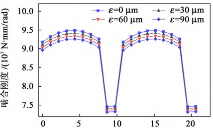
Under the condition of no error, the angular displacement of the center point of each lamella of the bevel gear increases first and then decreases from the tooth root to the tooth tip. This is due to the fact that only one pair of teeth is responsible for load bearing during single-tooth meshing, while two pairs of teeth are responsible for load bearing during double-tooth meshing, resulting in a large angular displacement during single-tooth meshing. As can be seen from the figure, the point that bears the maximum load is the large end of the bevel gear during single-tooth meshing. This is due to the fact that the meshing stiffness of the large end lamella is greater than that of the small end, resulting in a large torque being borne by the large end The angular displacement of the center point of the thin sheet at the small end of the gear is the largest due to the load applied. This is because the small end has the smallest angular deviation under the condition of axial misalignment, and it is the first to engage during the meshing process, resulting in the largest angular displacement of its center point among all the meshing sheets. As can be seen from the figure, the maximum load borne by the bevel gear is at the small end during single tooth meshing.
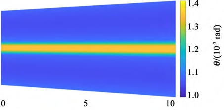
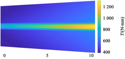
The assembly error of bevel gears causes severe unbalanced loads during transmission, resulting in meshing deformation and increased transmission errors, which reduces the load-carrying capacity of the spur bevel gear pair and seriously affects its service life. Therefore, in practical engineering, the installation accuracy of the bevel gear pair should be maximized to ensure its service life.
Conclusion
The following research was conducted to solve the problem of efficient calculation of time-varying meshing stiffness for spur bevel gears:
1) Based on the equivalent principle of the back cone, the bevel gear is equivalent to a series of spur gears, and the meshing stiffness of each sheet is calculated using the energy method. In the calculation of the double-tooth meshing stiffness, the coupling effect between tooth pairs is considered, and the wheel body stiffness correction factor is introduced using finite element method to reduce the calculation error of double-tooth meshing stiffness.
2) Comparing the method in this article, analytical method, and finite element calculation results, the results show that the error in calculating the single-tooth meshing stiffness using the method in this article is approximately 3%, and the error in calculating the double-tooth meshing stiffness is approximately 2%. Moreover, the calculation time is much shorter than that of finite element calculation, verifying the accuracy and efficiency of the method in this article.
3) By solving the angular displacement of the center point of each thin tooth pair of a straight bevel gear after loading, the meshing stiffness, angular displacement of each thin center point, and load distribution on the tooth surface under error conditions were calculated. Compared with finite element method, the accuracy of meshing stiffness calculation under error conditions was verified. The method combines the advantages of finite element method and analytical method, which greatly improves the efficiency of time-varying meshing stiffness calculation of bevel gears while maintaining high computational accuracy. In addition, it was also verified that the method in this paper still has accuracy under installation error conditions. However, it is worth noting that in addition to installation errors, the time-varying meshing stiffness of bevel gears is also affected by tooth profile errors caused by surface roughness, friction and lubrication during tooth surface meshing, which cannot be considered in this method and needs further improvement.
