
In my research, I focused on the thermal behavior of a high-power fan drive gearbox used in geared turbofan engines. The gearbox transmits 20 MW at an input speed of 7200 rpm through a five-branch herringbone planetary arrangement. Because the fan drive gearbox operates under severe conditions with high speed, heavy load, and compact structure, effective cooling and lubrication are critical. The pinion gears in the planetary stage are especially vulnerable to excessive temperature rise. I therefore investigated a rapid cooling technique based on opening oil return holes in the undercut groove of the pinion gears. Using computational fluid dynamics, I analyzed the flow field and temperature field before and after the opening. I also studied the under-race lubrication circuit of the pinion gear bearings to provide proper thermal boundary conditions. The following sections summarize my methodology, models, simulations, and findings.
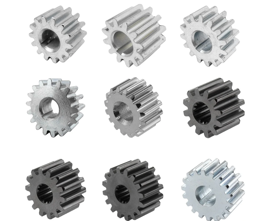
I began by establishing the geometric and operating parameters of the fan drive gearbox. The planetary train consists of one sun gear, five pinion gears, and one internal ring gear. The gear teeth are herringbone with a normal module of 3.75 mm, a normal pressure angle of 22.5°, and a helix angle of 28°. The sun gear has 41 teeth, each pinion gear has 40 teeth, and the internal ring gear has 127 teeth. The face width of each helical half is 65 mm for the sun gear, 64 mm for the pinion gears, and 63 mm for the internal ring gear. The tooth groove width is 35 mm, 36 mm, and 38 mm, respectively. The pinion gear cylindrical roller bearings have 13 rollers, each with a diameter of 18 mm and a length of 22 mm. The bearing inner diameter is 84 mm and the outer diameter is 120 mm. The gear material is 9310 steel with an elastic modulus of 207 GPa, a Poisson’s ratio of 0.28, a yield strength of 910 MPa, an ultimate strength of 1230 MPa, and a density of 7860 kg/m³. The lubricating oil has a dynamic viscosity of about 13 mPa·s at the supply temperature of 67 °C.
| Parameter | Sun gear | Pinion gears (5) | Internal ring gear |
|---|---|---|---|
| Number of teeth | 41 | 40 | 127 |
| Normal module (mm) | 3.75 | 3.75 | 3.75 |
| Normal pressure angle (°) | 22.5 | 22.5 | 22.5 |
| Helix angle (°) | 28 | 28 | 28 |
| Helical face width (mm) | 65 | 64 | 63 |
| Tooth groove width (mm) | 35 | 36 | 38 |
| Roller diameter (mm) | Roller length (mm) | Number of rollers | Inner diameter (mm) | Outer diameter (mm) |
|---|---|---|---|---|
| 18 | 22 | 13 | 84 | 120 |
| Material | Temperature (°C) | Elastic modulus (GPa) | Poisson’s ratio | Yield strength (MPa) | Ultimate strength (MPa) | Density (g/cm³) |
|---|---|---|---|---|---|---|
| 9310 steel | 100 | 207 | 0.28 | 910 | 1230 | 7.86 |
I calculated the frictional heat generation of the gear teeth using Hertz contact theory. For the herringbone gears, I treated each helical half as an equivalent helical gear. The contact line length varies with the meshing position, and I derived the total contact line length as the sum of the individual contact lines of all engaging tooth pairs. The transverse contact ratio and the overlap ratio determine the variation pattern. For external meshing, the transverse contact ratio is
$$\varepsilon_\alpha = \frac{1}{2\pi} \left[ z_1 (\tan \alpha_{at1} – \tan \alpha_t’) + z_2 (\tan \alpha_{at2} – \tan \alpha_t’) \right]$$
and for internal meshing,
$$\varepsilon_\alpha = \frac{1}{2\pi} \left[ z_1 (\tan \alpha_{at1} – \tan \alpha_t’) – z_2 (\tan \alpha_{at2} – \tan \alpha_t’) \right]$$
The overlap ratio is
$$\varepsilon_\beta = \frac{b \sin \beta}{\pi m_n}$$
The total contact ratio is
$$\varepsilon_\gamma = \varepsilon_\alpha + \varepsilon_\beta$$
I then computed the contact stress at any meshing point using the Hertzian line contact formula. For two cylinders in contact, the maximum contact pressure is
$$p_{nc} = \frac{4}{\pi} \sqrt{\frac{F_{nh}}{L} \frac{R_1 R_2}{R_1 \pm R_2} \left( \frac{1-\mu_1^2}{E_1} + \frac{1-\mu_2^2}{E_2} \right)}$$
where \(F_{nh}\) is the normal force at the contact point, \(L\) is the total contact line length, \(R_1\) and \(R_2\) are the radii of curvature, \(\mu_1\) and \(\mu_2\) are Poisson’s ratios, and \(E_1\) and \(E_2\) are elastic moduli. I found that the maximum contact stress between the sun gear and a pinion gear is about 780 MPa, while the minimum is about 690 MPa. For the internal meshing between a pinion gear and the ring gear, the maximum contact stress is about 620 MPa and the minimum is about 530 MPa. The contact stress fluctuates along the tooth profile and face width due to the varying contact line length.
Next, I determined the relative sliding velocity at the meshing points. For external meshing, the absolute velocities of the driving and driven gears along the line of action are
$$V_{c1} = \frac{\pi n_1}{60 \times 1000} \left( \frac{d_1}{2} \sin \alpha_t’ + g_{yc} \right)$$
$$V_{c2} = \frac{\pi n_2}{60 \times 1000} \left( \frac{d_2}{2} \sin \alpha_t’ – g_{yc} \right)$$
and the relative sliding velocity is
$$V_{gc} = V_{c1} – V_{c2} = \frac{\pi n_1}{60 \times 1000} \left( \frac{d_1}{2} \sin \alpha_t’ + g_{yc} \right) – \frac{\pi n_2}{60 \times 1000} \left( \frac{d_2}{2} \sin \alpha_t’ – g_{yc} \right)$$
For internal meshing, the signs are adjusted accordingly. I observed that the relative sliding velocity is zero at the pitch point and increases toward the addendum and dedendum. The maximum sliding velocity occurs near the tip and root.
The friction coefficient on the tooth surface was calculated using an empirical formula that accounts for normal load, sliding speed, rolling speed, and oil viscosity:
$$\mu_c = 0.0127 \lg \left( \frac{29.66 F_n}{\mu_o v_s v_t} \right)$$
where \(F_n\) is the average normal load, \(\mu_o\) is the dynamic viscosity of the oil, \(v_s\) is the average sliding speed, and \(v_t\) is the average rolling speed. The frictional heat flux on the meshing surface is then
$$q_g = \mu_c p_{nc} V_{gc}$$
I distributed this heat between the two meshing gears using a heat partition coefficient \(\beta\):
$$\beta = \frac{\sqrt{\lambda_1 \rho_1 c_{p1} V_1}}{\sqrt{\lambda_1 \rho_1 c_{p1} V_1} + \sqrt{\lambda_2 \rho_2 c_{p2} V_2}}$$
where \(\lambda\) is thermal conductivity, \(\rho\) is density, \(c_p\) is specific heat, and \(V\) is the tangential velocity. The heat fluxes into the driving and driven gears are \(q_{g1} = \beta q_g\) and \(q_{g2} = (1-\beta) q_g\). For the time-averaged heat flux over one rotation, I used
$$q_{gt} = q_g \frac{t_{gi}}{t_{Ti}}$$
where \(t_{gi}\) is the time for the contact region to pass a point and \(t_{Ti}\) is the rotational period. I found that the heat flux on the tooth surface exhibits a V-shaped distribution along the tooth height, being zero at the pitch point and increasing toward the tip and root. The sun gear as the driving gear has a higher heat flux at the root, while the pinion gear as the driven gear has a higher heat flux at the tip. For internal meshing, the pinion gear becomes the driving gear, and the ring gear is the driven gear. The overall heat flux in internal meshing is lower than in external meshing.
I also calculated the windage loss of the gears using Anderson’s empirical formula:
$$q_{wi} = 2.82 \times 10^{-7} \left( 1 + 2.3 \frac{b}{r_i} \right) n_i^{2.8} r_i^{4.6} \left( 0.019 + 0.028 \frac{b}{r_i} \right) \mu_o^{0.27}$$
where \(q_{wi}\) is the windage power loss in watts, \(b\) is the face width, \(r_i\) is the pitch radius, and \(n_i\) is the rotational speed. For the 20 MW gearbox, the total windage loss was found to be a small but non-negligible portion of the total power loss.
For the pinion gear cylindrical roller bearings, I used Palmgren’s model to compute the friction torque and heat generation. The total friction torque is
$$M = M_l + M_v$$
where \(M_l\) is the load-dependent torque and \(M_v\) is the viscous torque. The load-dependent torque is
$$M_l = f_1 F_\beta d_m$$
and the viscous torque for \(v_o n > 2000\) is
$$M_v = 10^{-7} f_2 (v_o n)^{2/3} d_m^3$$
For \(v_o n \leq 2000\),
$$M_v = 160 \times 10^{-7} f_2 d_m^3$$
Here \(d_m\) is the bearing pitch diameter, \(F_\beta\) is the equivalent dynamic load, \(v_o\) is the kinematic viscosity, and \(n\) is the rotational speed. The heat generation rate is
$$Q_b = 1.047 \times 10^{-4} M n$$
I computed the total heat generation for the entire gearbox. The sun gear loses about 32.0 kW, the five pinion gears lose about 61.2 kW, the internal ring gear loses about 25.6 kW, and the ten pinion gear bearings lose about 14.3 kW. The total power loss is about 135.1 kW, which is 0.675% of the 20 MW input power. This is consistent with the requirement that the loss should be below 0.7% to avoid overheating.
| Component | Power loss (kW) | Total gearbox loss (kW) | Loss ratio |
|---|---|---|---|
| Sun gear | 32.046 | 135.056 | 0.6753% |
| Pinion gears (5) | 61.222 | ||
| Internal ring gear | 25.628 | ||
| Pinion gear bearings (10) | 14.267 |
After establishing the heat sources, I turned to the under-race lubrication circuit of the pinion gear bearings. Because the pinion gears operate at high DN values, under-race lubrication is used to deliver oil directly to the bearing inner ring. I built a conjugate heat transfer model of the pinion gear pin and the bearing inner ring. The model included the axial oil supply passage, radial oil holes, and the annular gap between the pin and the inner ring. I used a tetrahedral mesh with inflation layers near the walls. The lubricant enters the axial passage, flows through radial holes, and cools the inner ring. I applied a constant heat flux of 50,513 W/m² to the inner ring raceway to represent the bearing friction heat.
In the baseline model without annular grooves, I found that the oil velocity in the axial passage decreases from the input side to the output side. The wall heat transfer coefficient on the input side is higher than on the output side, leading to a temperature difference of 13.1 °C between the two sides of the inner ring. The output side raceway reaches about 124 °C, while the input side reaches about 112 °C. To improve cooling and simplify assembly, I introduced annular oil supply grooves on the pin. I examined different groove widths and depths. The groove cross-section affects both the oil velocity and the heat transfer area. I calculated the average heat transfer coefficient and the groove area for various dimensions.
| Groove width (mm) | Groove depth (mm) | Oil velocity (m/s) | Average HTC (W/m²·K) | Groove area (mm²) |
|---|---|---|---|---|
| 2 | 1.5 | 1.52 | 980 | 1500 |
| 2 | 2.5 | 1.21 | 890 | 2500 |
| 3 | 1.5 | 1.18 | 820 | 2250 |
| 3 | 2.5 | 0.95 | 740 | 3750 |
| 4 | 1.5 | 0.92 | 710 | 3000 |
| 4 | 2.5 | 0.78 | 640 | 5000 |
| 5 | 1.5 | 0.75 | 620 | 3750 |
| 5 | 2.5 | 0.65 | 570 | 6250 |
The results showed that when the groove width is small, increasing the depth increases the heat transfer area and lowers the inner ring temperature. When the groove width is large, increasing the depth reduces the oil velocity and the heat transfer coefficient, causing the temperature to rise. An optimal groove cross-section of about 2 mm width and 1.5 mm depth reduced the output side inner ring temperature from 124 °C to about 109 °C and the input side from 112 °C to about 105 °C. The temperature distribution around the circumference also became more uniform.
I further introduced a splitter tube inside the axial oil passage to equalize the flow between the input and output sides. The splitter tube has radial holes that distribute the oil more evenly. With the splitter tube, the velocity difference between the two sides was greatly reduced, and the wall heat transfer coefficients on both sides became nearly equal. The inner ring temperatures on the input and output sides became 98.8 °C and 99.2 °C, respectively, showing a much smaller difference. I also conducted a validation test using two ring heaters to simulate the bearing heat generation. The test confirmed that increasing the annular groove width reduces the inner ring temperature, which is consistent with my simulation trends.
With the thermal boundary conditions from the under-race lubrication study, I then built a full CFD model of the fan drive gearbox. I simplified the geometry by removing the oil supply brackets, torque transfer brackets, and input/output shafts. I also used a single-tooth cutting method for the sun gear and the internal ring gear to avoid extremely small gaps in the meshing zone. I created a one-fifth periodic model of the solid and fluid domains. The mesh was tetrahedral with refinement near the gear surfaces, bearing surfaces, and periodic boundaries. I defined four oil inlets: one for the pinion gear bearing under-race lubrication, one for the external meshing mesh-in side, one for the external meshing mesh-out side, and one for the internal meshing mesh-in side. The oil supply temperatures were all 67 °C. The outlet was set as a pressure outlet. The rotating parts were set as moving walls with the appropriate rotational speeds: sun gear 7200 rpm, pinion gears 7380 rpm, and internal ring gear 2324.4 rpm.
I first analyzed the flow field before and after opening holes in the undercut groove of the pinion gears. The opening holes serve as oil return paths from the bearing cavity to the outside. I examined several cross-sections along the gearbox axis. In the baseline case without holes, the oil flow inside the bearing cavity was largely trapped and tended to exit mainly from the output side of the pinion gears. This is because the output side housing has a lower pressure. After opening holes of 10 × Φ12 mm, the flow field changed noticeably. The holes created additional radial velocity components due to centrifugal force, allowing oil to flow out of the bearing cavity. However, some holes located near the meshing-in region experienced backflow because of the positive pressure generated by the meshing action.
I studied the mass flow rate through the return holes for different hole diameters and numbers. The total mass flow rate increases linearly with hole diameter when the number of holes is fixed at 10. For diameters of 4 mm, 8 mm, 12 mm, 16 mm, 20 mm, and 24 mm, the total mass flow rates were approximately 1.1, 2.0, 2.9, 3.6, 4.2, and 4.7 kg/s, respectively. When the hole diameter is large, some holes exhibit negative mass flow due to backflow. The total mass flow rate increases nonlinearly with the number of holes. For 4, 6, 8, 10, and 12 holes at a diameter of 20 mm, the total mass flow rates were about 2.2, 3.2, 4.0, 4.2, and 4.3 kg/s. The increase slows down after about 8 holes.
| Hole diameter (mm) | Total mass flow (kg/s) | Number of holes | Total mass flow (kg/s) |
|---|---|---|---|
| 4 | 1.1 | 4 | 2.2 |
| 8 | 2.0 | 6 | 3.2 |
| 12 | 2.9 | 8 | 4.0 |
| 16 | 3.6 | 10 | 4.2 |
| 20 | 4.2 | 12 | 4.3 |
| 24 | 4.7 |
I also analyzed the turbulent intensity of the fluid near various walls. Turbulence enhances convective heat transfer. For the pinion gear bearing rollers, opening holes increased the average turbulent intensity on the roller cylindrical surface and end faces. The turbulent intensity increased with both hole diameter and hole number. For the bearing inner and outer rings, the effect was smaller at small hole diameters but became more significant at larger diameters. For the pinion gear tooth surfaces, opening holes generally decreased the turbulent intensity, especially at larger diameters. For the sun gear and internal ring gear, the turbulent intensity also tended to decrease with larger holes or more holes. This indicates that while opening holes improves oil return from the bearing cavity, it may reduce turbulence near the gear teeth, which could slightly degrade convective cooling of the gear surfaces.
Next, I performed the thermal analysis of the full gearbox. I loaded the heat fluxes from the gear friction, bearing friction, and windage losses. I also applied the convective heat transfer coefficients obtained from the flow simulations to the moving walls. For the outer surface of the output shaft housing, I used an empirical correlation for natural convection with air:
$$h = 0.32 \frac{\lambda_a}{l} Re^{0.65} Pr_a^{0.40}$$
where \(Re\) is the Reynolds number, \(Pr_a\) is the Prandtl number of air, \(\lambda_a\) is the thermal conductivity of air, and \(l\) is the characteristic length. I implemented this as a user-defined function.
The material properties used in the thermal analysis are listed in the following table.
| Component | Density (kg/m³) | Thermal conductivity (W/m·K) | Specific heat (J/kg·K) |
|---|---|---|---|
| Gears | 7862 | 495 | 33 |
| Bearings | 7875 | 475 | 44 |
| Planet carrier | 7851 | 541 | 43 |
| Bearing pins | 7783 | 502 | 17.2 |
Before opening holes, the temperature field showed that the pinion gear teeth are the hottest among the gears, followed by the sun gear, and the internal ring gear is the coolest. Among the bearing components, the rollers are the hottest, followed by the outer ring, and the inner ring is the coolest because of under-race cooling. The planet carrier pin bores on the output side are hotter than on the input side due to poorer heat dissipation. Along the face width of a pinion gear, the middle is hotter than the ends. Along the tooth height, there is a local temperature peak near the tip and another near the root, with a minimum near the pitch point.
I then studied the effect of hole diameter on the temperatures of the pinion gear bearings and gears. The average convective heat transfer coefficients on the bearing roller surfaces increased with hole diameter. Consequently, the roller temperatures decreased. For example, at a hole diameter of 24 mm, the roller temperature dropped by about 8 °C compared to the no-hole case. The bearing inner ring temperature first slightly increased and then decreased as the hole diameter increased, with a minimum around 12–16 mm. The outer ring temperature showed a small increase followed by a decrease. For the pinion gear tooth surface, the temperature increased with hole diameter on the input side and first decreased then increased on the output side. An optimum diameter of about 8 mm kept the pinion gear tooth temperature relatively low while not overheating the sun gear or ring gear. The sun gear tooth temperature was lowest around 8–12 mm, and the ring gear temperature increased gradually with hole diameter.
I also examined the effect of the number of holes at a fixed diameter of 20 mm. Increasing the number of holes increased the convective heat transfer coefficients on the bearing rollers and decreased the roller temperatures. The bearing inner ring temperature decreased after an initial slight rise when the number of holes exceeded 6. The outer ring temperature showed a maximum at about 8 holes. For the pinion gear tooth surface, the temperature first decreased and then increased with the number of holes, with a minimum around 4 holes. The sun gear tooth temperature increased with the number of holes beyond 6. The ring gear temperature increased steadily with the number of holes. Considering all components, I concluded that 4 holes of 8 mm diameter provide the best overall thermal performance, reducing the hottest pinion gear tooth temperature while avoiding excessive temperature rises in other components.
| Hole diameter (mm) | Pinion roller temperature (°C) | Pinion tooth temperature (°C) | Sun gear tooth temperature (°C) | Ring gear tooth temperature (°C) |
|---|---|---|---|---|
| No holes | 104 | 125 | 116 | 114 |
| 4 | 103 | 124 | 116 | 114 |
| 8 | 101 | 122 | 115 | 115 |
| 12 | 99 | 123 | 115 | 116 |
| 16 | 97 | 124 | 116 | 117 |
| 20 | 95 | 126 | 117 | 118 |
| 24 | 93 | 128 | 118 | 119 |
| Number of holes | Pinion roller temperature (°C) | Pinion tooth temperature (°C) | Sun gear tooth temperature (°C) | Ring gear tooth temperature (°C) |
|---|---|---|---|---|
| No holes | 104 | 125 | 116 | 114 |
| 4 | 103 | 122 | 115 | 114 |
| 6 | 101 | 123 | 115 | 115 |
| 8 | 99 | 125 | 116 | 116 |
| 10 | 97 | 127 | 117 | 117 |
| 12 | 95 | 129 | 118 | 118 |
My study demonstrates that opening oil return holes in the undercut groove of the pinion gears is a feasible rapid cooling technique for the fan drive gearbox. The holes allow the under-race lubricant to escape more quickly from the bearing cavity, reducing the temperature of the hottest bearing components. At the same time, the holes slightly reduce turbulence near the gear teeth, which can increase the gear tooth temperature if the holes are too large or too numerous. By optimizing the hole diameter and number, I achieved a net cooling benefit for the pinion gears while maintaining acceptable temperatures in the sun gear and ring gear. The annular oil supply grooves and splitter tube in the pinion gear pin further improve the under-race lubrication and reduce the temperature difference between the input and output sides of the bearing inner ring. The validated simulation approach and the thermal boundary conditions I developed can be used for further design and optimization of fan drive gearboxes with pinion gears in geared turbofan engines.
In summary, I constructed a comprehensive CFD-based thermal analysis framework for a high-power fan drive gearbox. I calculated the gear friction heat, windage loss, and bearing heat generation. I modeled the under-race lubrication circuit with conjugate heat transfer. I simulated the full gearbox flow field before and after opening oil return holes in the pinion gears. I analyzed the convective heat transfer and temperature distributions, and I identified the optimal hole parameters. The results show that the pinion gear tooth surface is the critical hot spot, and that opening a small number of medium-sized holes can effectively reduce the pinion gear bearing roller temperature and the pinion gear tooth temperature without causing excessive heating of other components. This work provides a new design method for rapid cooling of fan drive gearboxes and supports the development of more efficient and reliable geared turbofan engines.