
In this work, I investigate the thermal behavior of a fan drive gearbox used in a high-bypass-ratio geared turbofan engine. The central problem is that the fan drive gearbox must transmit very high power while remaining compact, lightly weighted, and sufficiently cooled. I focus on a planetary transmission with a sun gear, five pinion gears, and an internal ring gear. The pinion gear is supported by cylindrical roller bearings, and the bearing lubrication is supplied by an under-race oil path. To improve oil evacuation and reduce the accumulation of hot oil inside the pinion gear bearing cavity, I examine the effect of opening oil-return holes in the pinion gear cutter relief groove. The study is performed with computational fluid dynamics, coupled with heat-generation models for gears and bearings. I use the results to evaluate whether pinion gear opening and oil return can serve as a feasible fast-cooling method.
The fan drive gearbox operates at a maximum torque condition with 20 MW transmitted power and an input speed of 7200 r/min. Because the pinion gear rotates at high speed and carries a large bearing load, the thermal environment around the pinion gear is severe. The lubricating oil performs two functions: it reduces friction and it removes heat. If hot oil cannot leave the pinion gear bearing cavity quickly, the local temperature rises, the oil film thins, and the risk of scuffing or bearing distress increases. Therefore, I study both the flow field and the temperature field of the fan drive gearbox before and after pinion gear opening. The oil-return holes are placed in the pinion gear cutter relief groove, which is a geometrically convenient location for connecting the pinion gear bearing cavity to the surrounding oil collection region.
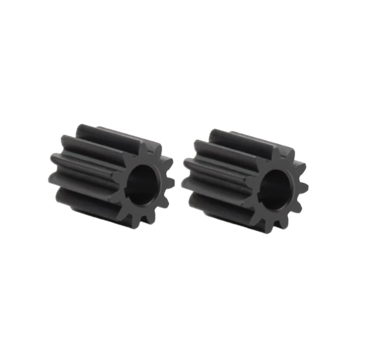
I organize the analysis into four main parts. First, I establish heat-generation models for the meshing gears and the pinion gear bearings. Second, I build a heat-fluid coupling model of the pinion gear pin and bearing inner ring to study under-race lubrication and to optimize the oil path. Third, I build a CFD model of the complete fan drive gearbox and compare the flow fields before and after pinion gear opening. Fourth, I load thermal boundary conditions onto the flow model and compute the temperature field for different hole diameters and hole numbers. The results show that the pinion gear opening and oil return strategy affects different components in different ways, and that a moderate hole diameter and hole number are preferable.
Nomenclature
| Symbol | Meaning | Unit |
|---|---|---|
| \(\alpha_t’\) | Operating pressure angle | degree |
| \(\alpha_{at1},\alpha_{at2}\) | Tip pressure angles of driving and driven gears | degree |
| \(b\) | Face width | mm |
| \(c_p\) | Specific heat capacity | J kg\(^{-1}\) K\(^{-1}\) |
| \(E_1,E_2\) | Elastic moduli | GPa |
| \(F_{nh}\) | Normal force at a contact point | N |
| \(g_{yc}\) | Position of a contact point on the line of action | mm |
| \(h\) | Convective heat transfer coefficient | W m\(^{-2}\) K\(^{-1}\) |
| \(k\) | Turbulent kinetic energy | m\(^2\) s\(^{-2}\) |
| \(L\) | Total contact line length | mm |
| \(l_i\) | Contact line length of the \(i\)-th tooth pair | mm |
| \(M\) | Bearing friction torque | N mm |
| \(P_{nc}\) | Average contact stress | MPa |
| \(P_{bt}\) | Transverse base pitch | mm |
| \(q_g\) | Friction heat flux on gear tooth surface | W m\(^{-2}\) |
| \(q_{wi}\) | Windage loss power | W |
| \(Q_b\) | Bearing heat generation | W |
| \(Q\) | Transmitted gear power | W |
| \(R_1,R_2\) | Radii of curvature at contact points | mm |
| \(Re\) | Reynolds number | – |
| \(T\) | Temperature | K or °C |
| \(v_{gc}\) | Relative sliding velocity | m s\(^{-1}\) |
| \(\beta_b\) | Base helix angle | degree |
| \(\beta\) | Heat partition coefficient | – |
| \(\varepsilon_\alpha\) | Transverse contact ratio | – |
| \(\varepsilon_\beta\) | Axial overlap ratio | – |
| \(\varepsilon_\gamma\) | Total contact ratio | – |
| \(\mu_c\) | Tooth friction coefficient | – |
| \(\mu_o\) | Dynamic viscosity of oil | Pa s |
| \(\rho\) | Density | kg m\(^{-3}\) |
| \(\lambda\) | Thermal conductivity | W m\(^{-1}\) K\(^{-1}\) |
Gearbox Configuration and Operating Conditions
I model a five-branch herringbone planetary transmission. The sun gear is the input member, the ring gear is connected to the output, and the five pinion gears are mounted on the carrier. A herringbone tooth form is used because it balances axial forces and provides smooth load transfer. For the thermal analysis, I treat each herringbone gear as two identical helical gear halves that mesh simultaneously. This simplification allows me to compute the tooth contact stress, sliding velocity, friction coefficient, and friction heat flux with a consistent set of equations.
| Parameter | Sun gear | Pinion gear | Ring gear |
|---|---|---|---|
| Number of teeth | 41 | 40 | 127 |
| Normal module (mm) | 3.75 | ||
| Normal pressure angle (°) | 22.5 | ||
| Helix angle (°) | 28 | ||
| Helical face width (mm) | 65 | 64 | 63 |
| Tooth groove width (mm) | 35 | 36 | 38 |
The pinion gear bearing is a cylindrical roller bearing. Its geometry is important because the bearing heat generation and the under-race oil flow both depend on the bearing envelope. I list the bearing data in the following table.
| Parameter | Value |
|---|---|
| Roller diameter (mm) | 18 |
| Roller length (mm) | 22 |
| Number of rollers | 13 |
| Inner ring diameter (mm) | 84 |
| Outer ring diameter (mm) | 120 |
The gear and bearing materials are assumed to be typical aviation bearing and gear steels. I use temperature-dependent oil viscosity. In the simulations, the oil supply temperature is 67 °C, and the corresponding dynamic viscosity is used unless otherwise stated.
| Material property | Value at 100 °C |
|---|---|
| Elastic modulus (GPa) | 207 |
| Poisson’s ratio | 0.28 |
| Yield strength (MPa) | 910 |
| Ultimate strength (MPa) | 1230 |
| Density (g cm\(^{-3}\)) | 7.86 |
Heat Generation Models
I compute the heat sources from gear meshing, gear windage, and bearing friction. The gear meshing heat is the most important source because the pinion gear tooth surface reaches the highest temperature in the transmission. The bearing heat source is also important because the pinion gear bearing is lubricated by an under-race path and is surrounded by hot oil.
Contact Ratio and Contact Line Length
For helical and herringbone gears, the total contact ratio is the sum of the transverse contact ratio and the axial overlap ratio:
$$
\varepsilon_\gamma = \varepsilon_\alpha + \varepsilon_\beta .
$$
For an external mesh, the transverse contact ratio is
$$
\varepsilon_\alpha =
\frac{1}{2\pi}
\left[
z_1\left(\tan\alpha_{at1}-\tan\alpha_t’\right)
+
z_2\left(\tan\alpha_{at2}-\tan\alpha_t’\right)
\right].
$$
For an internal mesh, the corresponding expression is
$$
\varepsilon_\alpha =
\frac{1}{2\pi}
\left[
z_1\left(\tan\alpha_{at1}-\tan\alpha_t’\right)
–
z_2\left(\tan\alpha_{at2}-\tan\alpha_t’\right)
\right].
$$
The axial overlap ratio is
$$
\varepsilon_\beta = \frac{b \sin\beta_b}{\pi m_n}.
$$
When the transverse contact ratio is larger than the axial overlap ratio, the contact line length of one tooth pair changes in four stages. I write the length as
$$
l_i =
\begin{cases}
0, & 0 \le s_i \le \varepsilon_\beta P_{bt}, \\
\dfrac{s_i-\varepsilon_\beta P_{bt}}{\sin\beta_b}, & \varepsilon_\beta P_{bt} < s_i \le \varepsilon_\alpha P_{bt}, \\
\dfrac{b}{\sin\beta_b}, & \varepsilon_\alpha P_{bt} < s_i \le \varepsilon_\beta P_{bt}+b\tan\beta_b, \\
\dfrac{\varepsilon_\gamma P_{bt}-s_i}{\sin\beta_b}, & \varepsilon_\beta P_{bt}+b\tan\beta_b < s_i \le \varepsilon_\gamma P_{bt}.
\end{cases}
$$
When the axial overlap ratio is larger than the transverse contact ratio, the expression becomes
$$
l_i =
\begin{cases}
0, & 0 \le s_i \le \varepsilon_\beta P_{bt}, \\
\dfrac{s_i-\varepsilon_\beta P_{bt}}{\sin\beta_b}, & \varepsilon_\beta P_{bt} < s_i \le \varepsilon_\beta P_{bt}+b\tan\beta_b, \\
\dfrac{b}{\sin\beta_b}, & \varepsilon_\beta P_{bt}+b\tan\beta_b < s_i \le \varepsilon_\alpha P_{bt}, \\
\dfrac{\varepsilon_\gamma P_{bt}-s_i}{\sin\beta_b}, & \varepsilon_\alpha P_{bt} < s_i \le \varepsilon_\gamma P_{bt}.
\end{cases}
$$
The total contact line length is the sum over all meshing tooth pairs:
$$
L = \sum_{i=1}^{N} l_i .
$$
For the pinion gear, the contact line length fluctuates as the gear rotates. This fluctuation produces a nonuniform contact stress and a nonuniform friction heat flux. I use the contact line length to distribute the normal load among the meshing teeth.
Contact Stress
At any contact point on the line of action, the normal force is related to the transmitted torque. I write
$$
F_{nh} = \frac{T_h}{r_h \cos\alpha_{nh}\cos\beta_h}.
$$
The normal pressure angle and the transverse pressure angle satisfy
$$
\tan\alpha_{nh} = \tan\alpha_{th}\cos\beta_h,
$$
$$
\tan\alpha_{nh} = \tan\alpha_t’\cos\beta_h.
$$
Using Hertz contact theory, the contact half-width for two parallel cylinders is
$$
2a =
\sqrt{
\frac{4F_{nh}}{\pi L}
\frac{
\frac{1-\mu_1^2}{E_1}+\frac{1-\mu_2^2}{E_2}
}{
\frac{1}{R_1}+\frac{1}{R_2}
}
}.
$$
The average contact stress on the tooth surface is
$$
P_{nc} =
\sqrt{
\frac{F_{nh}}{\pi L}
\frac{
\frac{1}{R_1}+\frac{1}{R_2}
}{
\frac{1-\mu_1^2}{E_1}+\frac{1-\mu_2^2}{E_2}
}
}.
$$
For the external mesh between the sun gear and the pinion gear, I obtain a maximum contact stress of about 780 MPa and a minimum of about 690 MPa. For the internal mesh between the pinion gear and the ring gear, the maximum contact stress is about 620 MPa and the minimum is about 530 MPa. The contact stress varies along the tooth profile and across the face width because the contact line length changes.
Sliding Velocity and Friction Coefficient
The absolute velocity of a contact point on the driving gear along the line of action is
$$
V_{c1} =
\frac{\pi n_1}{60 \times 1000}
\left(
\frac{d_1}{2}\sin\alpha_t’ + g_{yc}
\right),
$$
and for the driven gear it is
$$
V_{c2} =
\frac{\pi n_2}{60 \times 1000}
\left(
\frac{d_2}{2}\sin\alpha_t’ – g_{yc}
\right).
$$
The relative sliding velocity is therefore
$$
v_{gc} = V_{c1} – V_{c2}
=
\frac{\pi n_1}{60 \times 1000}
\left(
\frac{d_1}{2}\sin\alpha_t’ + g_{yc}
\right)
–
\frac{\pi n_2}{60 \times 1000}
\left(
\frac{d_2}{2}\sin\alpha_t’ – g_{yc}
\right).
$$
I use an engineering friction coefficient model that accounts for load, sliding speed, rolling speed, and oil viscosity:
$$
\mu_c =
0.0127
\left(
\frac{29.66}{F_n}
\right)
\lg
\left(
\frac{\mu_o}{b v_s v_t}
\right).
$$
The friction coefficient is not constant. It depends on the instantaneous contact conditions. For this reason, I calculate the friction heat flux at each contact point rather than using a single average value.
Friction Heat Flux and Heat Partition
The friction heat flux on the gear tooth surface is
$$
q_g = \mu_c P_{nc} v_{gc}.
$$
The heat is partitioned between the two meshing gears. I use the partition coefficient
$$
\beta =
\frac{
\lambda_1 \rho_1 c_{p1} V_1
}{
\lambda_1 \rho_1 c_{p1} V_1 +
\lambda_2 \rho_2 c_{p2} V_2
}.
$$
The heat fluxes entering the driving and driven gears are
$$
q_{g1} = \beta q_g,
$$
$$
q_{g2} = (1-\beta) q_g.
$$
Because the tooth is in mesh for only a short part of one revolution, I average the heat flux over one rotation period:
$$
q_{gt} =
\frac{q_g t_{mi}}{t_{Ti}}.
$$
The resulting heat flux distribution is V-shaped along the tooth height. The heat flux is largest near the tip and root and is zero at the pitch point, where the sliding velocity is zero. The pinion gear experiences a particularly important heat flux distribution because it is the highest-temperature gear in the transmission.
Windage Loss
I estimate the windage loss of each gear with an empirical correlation. The windage power loss is
$$
q_{wi} =
2.82 \times 10^{-7}
\left(1+2.3\frac{b}{r_i}\right)
n_i^{2.8}
r_i^{4.6}
\left(0.019+0.028\right).
$$
Although windage loss is smaller than meshing loss, it is not negligible at the high rotational speed of the fan drive gearbox. The windage loss contributes to the total heat load and affects the oil temperature.
Bearing Heat Generation
The pinion gear is supported by a cylindrical roller bearing. The bearing load is dominated by the tangential tooth force. I write the tangential force as
$$
F_t = \frac{30Q}{\pi n r_b}.
$$
The radial load on the bearing is
$$
F_r = F_t \tan\alpha_t’.
$$
For the pinion gear bearing, the total radial load is approximately \(2F_t\). The bearing friction torque is divided into a load-dependent part and a viscous part:
$$
M = M_l + M_v.
$$
The load-dependent friction torque is
$$
M_l = f_1 F_\beta d_m.
$$
The viscous friction torque is
$$
M_v =
\begin{cases}
10^{-7} f_2 (v_o n)^{2/3} d_m^3, & v_o n \ge 2000, \\
160 \times 10^{-7} f_2 d_m^3, & v_o n < 2000.
\end{cases}
$$
The bearing heat generation is
$$
Q_b = 1.047 \times 10^{-4} M n.
$$
I calculate the total heat generation of the fan drive gearbox and compare it with the allowable loss. The total power loss is about 135 kW for 20 MW transmitted power, which corresponds to a loss rate of about 0.675%. This value is consistent with the expectation that the gearbox loss should remain below about 0.7% to avoid excessive oil heating.
| Component | Power loss (kW) |
|---|---|
| Sun gear | 32.046 |
| Pinion gears (five) | 61.222 |
| Ring gear | 25.628 |
| Pinion gear bearings (ten) | 14.267 |
| Total | 135.056 |
Under-Race Lubrication of the Pinion Gear Bearing
I build a heat-fluid coupling model of the pinion gear pin and the bearing inner ring. The purpose is to study how the under-race oil path affects the temperature of the pinion gear bearing inner ring. In this model, the oil enters an axial supply passage, passes through radial holes, and then enters the bearing cavity. The pinion gear bearing inner ring receives heat from the bearing contact, and the oil removes part of this heat by convection.
Governing Equations and Turbulence Model
I solve the mass, momentum, and energy conservation equations. The mass conservation equation is
$$
\frac{\partial \rho}{\partial t}
+
\frac{\partial (\rho u)}{\partial x}
+
\frac{\partial (\rho v)}{\partial y}
+
\frac{\partial (\rho w)}{\partial z}
= 0.
$$
For an incompressible fluid, this reduces to
$$
\frac{\partial u}{\partial x}
+
\frac{\partial v}{\partial y}
+
\frac{\partial w}{\partial z}
= 0.
$$
The momentum conservation equations are
$$
\frac{\partial (\rho u)}{\partial t}
+
\nabla \cdot (\rho u \mathbf{V})
=
-\frac{\partial p}{\partial x}
+
\frac{\partial \tau_{xx}}{\partial x}
+
\frac{\partial \tau_{yx}}{\partial y}
+
\frac{\partial \tau_{zx}}{\partial z}
+
F_x,
$$
$$
\frac{\partial (\rho v)}{\partial t}
+
\nabla \cdot (\rho v \mathbf{V})
=
-\frac{\partial p}{\partial y}
+
\frac{\partial \tau_{xy}}{\partial x}
+
\frac{\partial \tau_{yy}}{\partial y}
+
\frac{\partial \tau_{zy}}{\partial z}
+
F_y,
$$
$$
\frac{\partial (\rho w)}{\partial t}
+
\nabla \cdot (\rho w \mathbf{V})
=
-\frac{\partial p}{\partial z}
+
\frac{\partial \tau_{xz}}{\partial x}
+
\frac{\partial \tau_{yz}}{\partial y}
+
\frac{\partial \tau_{zz}}{\partial z}
+
F_z.
$$
The energy equation is
$$
\frac{\partial (\rho T)}{\partial t}
+
\nabla \cdot (\rho \mathbf{V} T)
=
\nabla \cdot
\left(
\frac{k_{oil}}{c_p} \nabla T
\right)
+
S_T.
$$
Because the flow inside the gearbox is turbulent, I use the realizable \(k\)-\(\varepsilon\) model. The turbulent kinetic energy equation is
$$
\frac{\partial (\rho k)}{\partial t}
+
\frac{\partial (\rho k u_i)}{\partial x_i}
=
\frac{\partial}{\partial x_j}
\left[
\left(\mu+\frac{\mu_t}{\sigma_k}\right)
\frac{\partial k}{\partial x_j}
\right]
+
G_k
–
\rho \varepsilon.
$$
The dissipation rate equation is
$$
\frac{\partial (\rho \varepsilon)}{\partial t}
+
\frac{\partial (\rho \varepsilon u_i)}{\partial x_i}
=
\frac{\partial}{\partial x_j}
\left[
\left(\mu+\frac{\mu_t}{\sigma_\varepsilon}\right)
\frac{\partial \varepsilon}{\partial x_j}
\right]
+
C_{1\varepsilon}
\frac{\varepsilon}{k}G_k
–
C_{2\varepsilon}\rho
\frac{\varepsilon^2}{k}.
$$
These equations are solved for the oil flow inside the under-race path and for the oil flow inside the complete gearbox. The turbulence model is important because the oil flow is highly unsteady and three-dimensional.
Mesh and Boundary Conditions
I use tetrahedral unstructured meshes because the under-race oil path contains small radial holes and a large axial passage. Inflation layers are placed on the fluid-solid interfaces to resolve the near-wall velocity and temperature gradients. The oil density is 964 kg m\(^{-3}\), the dynamic viscosity is 0.01333 kg m\(^{-1}\) s\(^{-1}\), and the thermal conductivity is 0.156 W m\(^{-1}\) K\(^{-1}\). The mass flow inlet is 0.02008 kg s\(^{-1}\). The heat flux on the bearing inner ring raceway is 50513 W m\(^{-2}\), based on the bearing heat generation.
Flow Field in the Under-Race Path
The oil enters the axial passage and forms a recirculation zone near the input side. The oil then distributes into the radial holes. The velocity in the radial holes reaches about 5 m s\(^{-1}\), while the axial velocity is much lower. The axial velocity decreases from the input side to the output side. As a result, the convective heat transfer coefficient on the axial passage wall is higher on the input side than on the output side. This difference causes the output-side bearing inner ring raceway to be about 13.1 °C hotter than the input-side raceway.
Effect of the Ring Groove
I introduce an annular supply groove between the pinion gear pin and the bearing inner ring. The groove connects the radial holes and reduces the alignment requirement between the pin and the inner ring. More importantly, the groove increases the wetted area and changes the oil velocity. I test several groove widths and depths. The groove wall convective heat transfer coefficient decreases as the groove depth or width increases because the oil velocity decreases. However, the groove area increases linearly with width and depth. The net effect on the bearing inner ring temperature depends on the competition between area and heat transfer coefficient.
| Groove width (mm) | Groove depth (mm) | Average groove HTC (W m\(^{-2}\) K\(^{-1}\)) | Groove area (mm\(^2\)) | Output-side inner ring temperature (°C) | Input-side inner ring temperature (°C) |
|---|---|---|---|---|---|
| 2 | 1.5 | 980 | 1500 | 109.4 | 105.3 |
| 2 | 2.5 | 820 | 2500 | 107.6 | 103.8 |
| 3 | 1.5 | 760 | 2250 | 108.9 | 104.6 |
| 4 | 1.5 | 620 | 3000 | 109.8 | 105.5 |
| 5 | 1.5 | 520 | 3750 | 111.2 | 106.4 |
The best cooling is obtained for a relatively small groove depth and a moderate width. When the groove is too wide or too deep, the oil velocity drops and the heat transfer coefficient decreases. The ring groove therefore provides both an assembly benefit and a thermal benefit, but its cross-section must be selected carefully.
Effect of the Splitter Tube
I add a splitter tube inside the axial supply passage to reduce the axial velocity difference between the input and output sides. The splitter tube is made of aluminum alloy to keep the added mass low. Oil passes through radial holes in the splitter tube and then enters the annular groove. With the splitter tube, the velocity field becomes nearly symmetric about the mid-plane. The convective heat transfer coefficients on the two monitored surfaces become much closer.
| Configuration | Left monitored surface HTC (W m\(^{-2}\) K\(^{-1}\)) | Right monitored surface HTC (W m\(^{-2}\) K\(^{-1}\)) |
|---|---|---|
| Without splitter tube | 71.6 | 169.3 |
| With splitter tube | 362.5 | 368.3 |
After adding the splitter tube, the input-side and output-side pinion gear bearing inner ring temperatures become 98.8 °C and 99.2 °C, respectively. The temperature difference is very small. This result shows that the splitter tube is effective for reducing the thermal asymmetry of the pinion gear bearing inner ring.
Experimental Validation
I designed a test rig to validate the effect of the ring groove cross-section on the pinion gear bearing inner ring temperature. Two annular heaters simulate the bearing friction heat source. A hydraulic pump supplies oil to the under-race path. Thermocouples measure the temperature at the input and output sides. The test confirms that the output-side temperature is higher than the input-side temperature when no splitter tube is used. The test also confirms that increasing the groove width reduces the inner ring temperature within the tested range. The measured trend agrees with the CFD prediction.
| Groove cross-section (mm) | Output-side measured temperature (°C) | Input-side measured temperature (°C) |
|---|---|---|
| 3 × 1.5 | 73.5 | 70.8 |
| 4 × 1.5 | 72.3 | 69.9 |
| 5 × 1.5 | 71.2 | 68.7 |
CFD Model of the Complete Fan Drive Gearbox
I build a simplified model of the complete fan drive gearbox. The model includes the sun gear, the five pinion gears, the ring gear, the carrier, the pinion gear pins, and the pinion gear bearings. The input shaft, output shaft, and some brackets are omitted to reduce mesh size. I use a one-fifth periodic sector to reduce computational cost. The sun gear and ring gear are cut with a single-tooth method to avoid extremely small gaps in the mesh region.
The oil inlets include the under-race oil inlet for the pinion gear bearing, the external mesh inlet, the external mesh outlet, and the internal mesh inlet. The inlet conditions are listed in the following table.
| Oil inlet location | Diameter (mm) | Type | Velocity (m s\(^{-1}\)) | Supply temperature (°C) |
|---|---|---|---|---|
| Pinion gear bearing under-race inlet | 1.6 | Velocity inlet | 3.228 | 67 |
| Pinion gear internal mesh inlet | 1.9 | Velocity inlet | 21.04 | 67 |
| Pinion gear external mesh inlet side | 2.0 | Velocity inlet | 17.71 | 67 |
| Pinion gear external mesh outlet side | 2.6 | Velocity inlet | 17.72 | 67 |
The rotating speeds of the main components are listed below. The sun gear rotates at 7200 r/min, the pinion gear rotates at 7380 r/min, and the ring gear rotates at 2324.4 r/min.
| Component | Rotational speed (r/min) |
|---|---|
| Sun gear | 7200 |
| Pinion gear | 7380 |
| Ring gear | 2324.4 |
Flow Field Before and After Pinion Gear Opening
I compare the flow field before and after opening oil-return holes in the pinion gear cutter relief groove. I use several hole diameters and hole numbers. The hole diameter ranges from 4 mm to 24 mm, and the hole number ranges from 4 to 12. The oil-return holes connect the pinion gear bearing cavity to the surrounding region. The flow field is evaluated in terms of velocity, pressure, streamlines, mass flow through the holes, and turbulent intensity.
Velocity Field
Before opening, the oil inside the pinion gear bearing cavity is stirred mainly by the bearing rollers and by the pinion gear rotation. The oil velocity is high near the gear mesh and near the ring gear oil return groove, but it decreases rapidly away from the moving walls. After opening, the oil-return holes in the pinion gear cutter relief groove introduce a radial velocity component. The oil near the holes is accelerated, and the velocity distribution in the relief groove changes significantly. The effect is local at small hole diameters and becomes more global at large hole diameters.
The velocity field also shows that the oil in the external mesh region is strongly influenced by the meshing pressure. Near the mesh inlet, the positive pressure pushes oil into the mesh zone. Near the mesh outlet, the pressure is lower, and the oil is drawn away. The pinion gear opening changes the balance between these regions.
Pressure Field
The pressure field is positive near the mesh inlet and near the outer edge of the ring gear. It is negative near the mesh outlet and in the output-side cavity. When holes are opened in the pinion gear, the windward side of each hole experiences a local positive pressure. This local pressure modifies the pressure distribution in the relief groove. For large holes located in the mesh inlet region, the local pressure can drive oil back into the pinion gear bearing cavity.
Oil Streamlines
The oil streamlines show that the oil in the mesh region is deflected by the relative motion of the teeth. At the external mesh inlet, part of the oil enters the mesh and part is deflected into the adjacent mesh outlet. At the external mesh outlet, the oil jet is directed opposite to the local oil velocity, so the oil does not enter the mesh and instead splashes onto the nearby tooth surfaces. At the internal mesh inlet, the oil jet is also deflected by the positive pressure.
For the pinion gear bearing, the under-race oil leaves the bearing cavity mainly from the output side when no holes are opened. This is because the output-side cavity has a lower pressure. When holes are opened in the pinion gear cutter relief groove, part of the oil leaves through the holes. This shortens the oil residence time in the bearing cavity and reduces the amount of hot oil that remains near the pinion gear bearing.
Mass Flow Through the Oil-Return Holes
I compute the mass flow through each oil-return hole. The sign of the mass flow indicates the direction. A positive value means oil flows out of the pinion gear bearing cavity, and a negative value means oil flows back into the cavity. For small holes, all holes have positive mass flow. For large holes, some holes located in the mesh inlet region have negative mass flow because the local pressure is high. The total mass flow out of the bearing cavity increases linearly with hole diameter when the hole number is fixed.
| Hole diameter (mm) | Total positive mass flow (kg s\(^{-1}\)) | Total negative mass flow (kg s\(^{-1}\)) | Net mass flow (kg s\(^{-1}\)) |
|---|---|---|---|
| 4 | 0.32 | 0.00 | 0.32 |
| 8 | 1.05 | 0.00 | 1.05 |
| 12 | 2.12 | 0.18 | 1.94 |
| 16 | 3.05 | 0.52 | 2.53 |
| 20 | 3.86 | 0.91 | 2.95 |
| 24 | 4.42 | 1.38 | 3.04 |
When the hole number is varied at a fixed hole diameter of 20 mm, the total mass flow increases nonlinearly with hole number. The increase is relatively slow between 6 and 10 holes.
| Hole number | Total mass flow (kg s\(^{-1}\)) |
|---|---|
| 4 | 1.85 |
| 6 | 2.46 |
| 8 | 2.82 |
| 10 | 2.95 |
| 12 | 3.42 |
Turbulent Intensity
Turbulent intensity is important because it enhances convective heat transfer. I evaluate the average turbulent intensity on the walls of the pinion gear bearing rollers, the bearing inner and outer rings, the pinion gear, the sun gear, and the ring gear. The pinion gear opening changes the turbulent intensity in different ways for different components.
For the pinion gear bearing rollers, the turbulent intensity increases with hole diameter and hole number. This is favorable for roller cooling. For the pinion gear bearing inner ring, the turbulent intensity changes only slightly at small hole diameters and increases at large hole diameters. For the pinion gear bearing outer ring, the turbulent intensity first decreases and then increases as the hole diameter or hole number increases.
For the pinion gear tooth surface, the turbulent intensity decreases as the hole diameter increases. For the sun gear and ring gear, the turbulent intensity also tends to decrease at large hole diameters or large hole numbers. This means that a large opening may improve the flow near the pinion gear bearing but may reduce the convective heat transfer on the gear tooth surfaces. This trade-off is important for selecting the opening parameters.
| Hole diameter (mm) | Pinion gear roller turbulent intensity (%) | Pinion gear tooth turbulent intensity (%) | Sun gear tooth turbulent intensity (%) | Ring gear tooth turbulent intensity (%) |
|---|---|---|---|---|
| No hole | 112 | 330 | 470 | 310 |
| 4 | 118 | 326 | 472 | 306 |
| 8 | 126 | 318 | 468 | 298 |
| 12 | 136 | 308 | 460 | 286 |
| 16 | 148 | 298 | 450 | 274 |
| 20 | 160 | 288 | 440 | 262 |
| 24 | 170 | 278 | 430 | 250 |
Temperature Field of the Complete Fan Drive Gearbox
I load the heat-generation boundary conditions and the convective boundary conditions onto the complete gearbox model. The heat flux on the gear tooth surfaces is applied with a user-defined function. The bearing heat generation is converted to a surface heat flux on the bearing raceways. The outer surface of the output housing exchanges heat with the surrounding air, and I use an empirical correlation for the external convective heat transfer coefficient.
Convective Heat Transfer Coefficients
The convective heat transfer coefficient on each moving wall depends on the local oil velocity and turbulence. The gear tooth surfaces have the highest coefficients because the tooth velocity is very high. The pinion gear bearing surfaces have lower coefficients because the roller and cage velocities are lower. The input-side surfaces generally have slightly higher coefficients than the output-side surfaces because the input-side oil flow is stronger.
| Surface | Output-side average HTC (W m\(^{-2}\) K\(^{-1}\)) | Input-side average HTC (W m\(^{-2}\) K\(^{-1}\)) |
|---|---|---|
| Pinion gear bearing inner ring | 715.3 | 719.2 |
| Pinion gear bearing outer ring | 1316.6 | 1332.4 |
| Pinion gear bearing roller | 790.4 | 811.5 |
| Pinion gear tooth surface | 2581.4 | 2602.2 |
| Sun gear tooth surface | 3859.2 | 3891.5 |
| Ring gear tooth surface | 2591.8 | 2758.2 |
Baseline Temperature Field Without Pinion Gear Opening
Without pinion gear opening, the highest temperature occurs on the pinion gear tooth surface. The sun gear is the second hottest, and the ring gear is cooler. Among the pinion gear bearing components, the roller temperature is the highest, the outer ring is next, and the inner ring is the lowest because it is cooled by the under-race oil. The output-side pinion gear pin bore is hotter than the input-side pin bore because the output-side cavity has weaker oil exchange.
| Component | Maximum temperature (°C) |
|---|---|
| Pinion gear tooth | 124.8 |
| Sun gear tooth | 116.5 |
| Ring gear tooth | 112.0 |
| Pinion gear bearing roller | 104.6 |
| Pinion gear bearing outer ring | 101.2 |
| Pinion gear bearing inner ring | 95.4 |
Along the face width of the pinion gear, the middle of the tooth is hotter than the two end faces because the middle has a longer thermal path to the end faces. Along the tooth height, there is a high-temperature peak near the tooth tip and a lower-temperature peak near the root. The tip is hotter because the friction heat flux is high there and because the thermal resistance to the gear body is large.
Effect of Hole Diameter
I vary the hole diameter while keeping the hole number at 10. The roller convective heat transfer coefficient increases with hole diameter. As a result, the roller temperature decreases. The inner ring temperature first increases slightly and then decreases when the hole diameter exceeds 12 mm. The outer ring temperature first increases and then decreases, but the variation is modest.
| Hole diameter (mm) | Roller temperature (°C) | Inner ring temperature (°C) | Outer ring temperature (°C) | Pinion gear tooth temperature (°C) |
|---|---|---|---|---|
| No hole | 104.6 | 95.4 | 101.2 | 124.8 |
| 4 | 104.1 | 95.6 | 101.5 | 124.3 |
| 8 | 103.3 | 95.5 | 101.3 | 123.6 |
| 12 | 102.2 | 95.2 | 101.0 | 123.8 |
| 16 | 101.0 | 94.6 | 100.6 | 124.5 |
| 20 | 99.8 | 94.0 | 100.2 | 125.8 |
| 24 | 98.5 | 93.3 | 99.8 | 127.2 |
The pinion gear tooth temperature first decreases slightly and then increases as the hole diameter becomes large. This is because the tooth surface convective heat transfer coefficient decreases at large hole diameters. Since the pinion gear tooth is the hottest component, a large hole diameter is not desirable. A hole diameter of about 8 mm gives a good balance: the roller temperature is reduced, and the pinion gear tooth temperature is also reduced.
The sun gear and ring gear temperatures also change with hole diameter. The sun gear tooth temperature first decreases slightly and then increases. The ring gear tooth temperature tends to increase as the hole diameter increases. These trends further support the selection of a moderate hole diameter.
| Hole diameter (mm) | Sun gear tooth temperature (°C) | Ring gear tooth temperature (°C) |
|---|---|---|
| No hole | 116.5 | 112.0 |
| 4 | 116.2 | 112.4 |
| 8 | 115.8 | 112.9 |
| 12 | 116.0 | 113.6 |
| 16 | 116.8 | 114.5 |
| 20 | 117.9 | 115.6 |
| 24 | 118.6 | 116.4 |
Effect of Hole Number
I vary the hole number while keeping the hole diameter at 20 mm. The roller temperature decreases as the hole number increases because the roller convective heat transfer coefficient increases. The inner ring temperature first increases slightly and then decreases. The outer ring temperature first increases and then decreases, with a maximum near 8 holes.
| Hole number | Roller temperature (°C) | Inner ring temperature (°C) | Outer ring temperature (°C) | Pinion gear tooth temperature (°C) |
|---|---|---|---|---|
| No hole | 104.6 | 95.4 | 101.2 | 124.8 |
| 4 | 103.2 | 95.7 | 101.4 | 123.9 |
| 6 | 102.0 | 95.5 | 101.1 | 124.3 |
| 8 | 100.8 | 95.0 | 100.8 | 125.2 |
| 10 | 99.8 | 94.0 | 100.2 | 126.5 |
| 12 | 98.6 | 93.1 | 99.7 | 128.3 |
The pinion gear tooth temperature increases when the hole number becomes large. This is again because the tooth surface convective heat transfer coefficient decreases. The sun gear and ring gear temperatures also increase as the hole number increases beyond 4. Therefore, a small hole number is preferable if the objective is to limit the temperature of the hottest gear tooth.
| Hole number | Sun gear tooth temperature (°C) | Ring gear tooth temperature (°C) |
|---|---|---|
| No hole | 116.5 | 112.0 |
| 4 | 116.1 | 112.6 |
| 6 | 116.2 | 113.4 |
| 8 | 116.6 | 114.2 |
| 10 | 117.3 | 115.1 |
| 12 | 118.2 | 116.0 |
Selection of Opening Parameters
The results show a trade-off. Opening the pinion gear cutter relief groove improves oil return from the pinion gear bearing cavity. This reduces the roller temperature and the inner ring temperature. However, when the holes are too large or too numerous, the flow near the gear teeth is disturbed, and the convective heat transfer coefficient on the pinion gear tooth surface decreases. Since the pinion gear tooth is the hottest component, this can increase the maximum gearbox temperature.
Based on the simulations, I recommend a moderate opening configuration. A hole diameter of about 8 mm and a hole number of about 4 provide a favorable balance. In this configuration, the pinion gear bearing roller temperature decreases, the pinion gear tooth temperature decreases slightly, and the temperatures of the sun gear and ring gear increase only slightly. If the oil-return requirement is more important than the gear tooth temperature, a larger hole diameter or hole number can be used, but the resulting increase in gear tooth temperature should be considered.
Discussion
The thermal analysis shows that the fan drive gearbox has two distinct thermal zones. The first zone is the gear mesh region, where the tooth surface temperature is high because of friction heat generation. The pinion gear is the most critical component in this zone. The second zone is the pinion gear bearing cavity, where the bearing rollers and raceways generate heat and rely on under-race oil for cooling. The oil-return holes in the pinion gear cutter relief groove connect these two zones and change the oil exchange between them.
The under-race lubrication study shows that the oil path design has a strong effect on the pinion gear bearing inner ring temperature. The annular groove increases the wetted area and reduces the alignment sensitivity. The splitter tube reduces the axial velocity difference and makes the temperature distribution more uniform. These design features are beneficial for the pinion gear bearing, but they also interact with the oil-return holes because the holes change the pressure field in the bearing cavity.
The flow field study shows that the oil-return holes produce a radial jet. This jet increases the local turbulent intensity and improves the convective heat transfer on the roller and inner ring surfaces. However, the same holes also disturb the oil flow around the gear teeth. At large hole diameters or large hole numbers, the turbulent intensity on the pinion gear, sun gear, and ring gear tooth surfaces decreases. This is why the gear tooth temperature can increase even though the bearing temperature decreases.
The temperature field study shows that the optimal opening parameters depend on the objective. If the objective is to minimize the pinion gear bearing temperature, a larger hole diameter and a larger hole number are better. If the objective is to minimize the maximum gearbox temperature, a moderate hole diameter and a small hole number are better. In this work, I find that a hole diameter of 8 mm and a hole number of 4 are a reasonable compromise.
The heat generation calculation also provides a useful check on the overall thermal design. The total power loss is about 135 kW for 20 MW transmitted power, which is about 0.675%. This is close to the allowable loss limit for a high-power fan drive gearbox. The pinion gear contributes the largest share of the gear mesh loss, and the pinion gear bearings contribute a smaller but still important share. The under-race oil flow must therefore be designed to remove heat from both the pinion gear tooth and the pinion gear bearing.
Conclusions
I performed a CFD-based thermal analysis of a fan drive gearbox with pinion gear opening and oil return. The main conclusions are as follows.
First, the pinion gear is the hottest gear in the fan drive gearbox. The friction heat flux on the pinion gear tooth surface is V-shaped along the tooth height, with peaks near the tip and root and a zero value at the pitch point. The pinion gear bearing roller is the hottest bearing component, followed by the outer ring and then the inner ring.
Second, the under-race oil path has a strong influence on the pinion gear bearing inner ring temperature. An annular supply groove increases the convective area and reduces the alignment requirement. A splitter tube reduces the axial velocity difference and makes the input-side and output-side temperatures nearly equal. The experimental test confirms the trend predicted by the CFD model.
Third, the pinion gear opening and oil return alters the flow field in the gearbox. The oil-return holes produce a radial jet, increase the turbulent intensity near the pinion gear bearing, and increase the total oil mass flow out of the bearing cavity. The total mass flow increases linearly with hole diameter and nonlinearly with hole number.
Fourth, the pinion gear opening and oil return has a trade-off effect on the temperature field. Small or moderate holes reduce the pinion gear bearing roller temperature and can slightly reduce the pinion gear tooth temperature. Large holes or many holes reduce the bearing temperature further but increase the pinion gear tooth temperature because the convective heat transfer on the gear tooth surfaces decreases.
Fifth, based on the CFD results, a hole diameter of about 8 mm and a hole number of about 4 are recommended for the pinion gear cutter relief groove. This configuration improves oil return from the pinion gear bearing cavity while avoiding an excessive increase in the maximum gearbox temperature. The results show that pinion gear opening and oil return is a feasible fast-cooling method, but the opening parameters must be selected carefully to balance bearing cooling and gear tooth cooling.
In future work, I plan to extend the model to include more detailed bearing dynamics, transient thermal effects, and the influence of pinion gear opening on gearbox modal behavior and meshing characteristics. I also plan to consider non-circular oil-return holes and different hole orientations to further optimize the cooling performance of the pinion gear and its bearing cavity.