
In my experience managing heavy industrial machinery, the failure of critical components like the helical bevel gear in a vertical mill reducer represents a significant operational challenge. This detailed account documents a firsthand investigation, root cause analysis, and the implemented engineering solutions following a catastrophic failure of the input shaft’s small helical bevel gear in a KMPS446 reducer powering a raw mill. The goal is to provide a deep technical understanding and a framework for preventive maintenance, heavily focusing on the dynamics and integrity of helical bevel gear pairs.
The vertical mill in question, a core component for raw meal preparation, experienced an unplanned shutdown triggered by elevated bearing temperature on the non-load side of the main motor. Subsequent inspection revealed severe damage to the input shaft’s helical bevel gear, a failure that threatened months of production downtime due to long lead times for original parts. This event initiated a comprehensive repair and root-cause analysis project, where we decided to proceed with a localized repair strategy, including the substitution of the original helical bevel gear set with a domestically manufactured equivalent. The entire process, from failure to successful recommissioning, underscored the criticality of precise alignment, lubrication, and monitoring in helical bevel gear systems.
System Parameters and Configuration
The drive system consists of a high-power motor and a three-stage reduction gearbox. The precise specifications are fundamental to understanding the operational stresses on the helical bevel gear.
| Component | Specification |
|---|---|
| Motor Type | YRKK800-6 |
| Motor Power | 2,700 kW |
| Motor Speed | 993 rpm |
| Reducer Model | KMPS446 |
| Reducer Input Power | 2,650 kW |
| Reducer Output Speed | 26.09 rpm |
| Reduction Ratio | Approximately 38:1 |
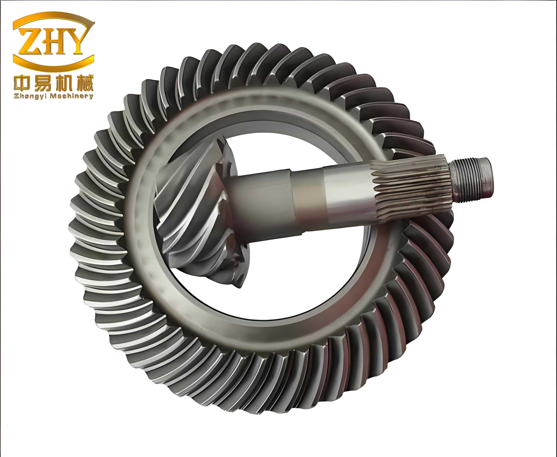
| Transmission Stages | Bevel Gear (Helical Bevel Gear) → Parallel Shaft → Planetary Gear |
The power transmission path initiates at the high-speed input shaft, where the primary torque conversion happens through the mating pair of helical bevel gears. The condition of this helical bevel gear interface is paramount for smooth power transfer and overall system longevity.
Detailed Failure Manifestation and Components Assessment
Upon disassembly at the repair facility, a systematic examination of the reducer’s internal components was conducted. The damage was not isolated to the helical bevel gear but formed a cascade of failures.
| Failed Component | Observed Damage Description | Implication for Helical Bevel Gear Operation |
|---|---|---|
| Input Shaft Small Helical Bevel Gear | Catastrophic tooth fracture across approximately one-third of the face width at the heel (large end). | Direct failure point; loss of meshing integrity causing immediate shutdown. |
| Input Shaft Rear Bearing (23244 CCW33 C3) | Cage destruction, severe rolling element deformation, spalling on inner and outer races. | Loss of radial and axial support for the input shaft, leading to shaft misalignment and altered helical bevel gear contact pattern. |
| Input Shaft Sleeve | Evidence of fretting (rotation relative to housing) and cracking at the bearing seat. | Compromised bearing seat integrity exacerbates misalignment forces on the helical bevel gear. |
| Sun Gear, Planet Gears, Internal Ring Gear | Localized pitting and spalling on tooth flanks; contact pattern biased towards one end (~100-130 mm length). | Indicates misalignment in the planetary stage, potentially linked to primary shaft deflections from the failed helical bevel gear stage. |
| Intermediate Shaft Drum Tooth Coupling | Circumferential wear on the spherical sealing contact surface. | Suggests axial movement or misalignment, possibly related to the failure cascade initiated upstream at the helical bevel gear. |
| Various Other Bearings | Widespread indentations from debris (fragments from the failed helical bevel gear and bearings). | Secondary damage due to contamination from the primary helical bevel gear failure. |
The pivotal observation was that the failure of the helical bevel gear was a symptom, not the sole root cause. The sequence appeared to begin with bearing degradation, which progressively misaligned the delicate meshing of the helical bevel gear pair until overload and fracture occurred.
Root Cause Analysis: A Quantitative and Qualitative Investigation
Analyzing operational data and physical evidence led to a multi-factorial root cause model. The health of the helical bevel gear is exquisitely sensitive to alignment and bearing condition.
1. Bearing Failure and Axial Play: The intermediate bearing (29340E) on the input shaft was found with excessive axial clearance, measured at 0.45 mm against a specification of 0.10–0.15 mm. This excessive play can be modeled as an introduced axial displacement $\Delta_{axial}$ that directly impacts the meshing geometry of the helical bevel gear. The contact pattern shifts from the ideal central position towards the toe or heel. The resulting edge loading dramatically increases contact stress ($\sigma_H$), which can be approximated by the modified Hertzian contact stress formula for gear teeth:
$$ \sigma_H = Z_E \sqrt{ \frac{F_t}{b d_1} \cdot \frac{u \pm 1}{u} \cdot K_A K_V K_{H\beta} K_{H\alpha} } $$
Where $F_t$ is the tangential load, $b$ is the face width, $d_1$ is the pinion pitch diameter, $u$ is the gear ratio, and $Z_E$ is the elasticity factor. The factors $K_{H\beta}$ (face load factor) and $K_{H\alpha}$ (transverse load factor) increase significantly with misalignment. For a helical bevel gear, even a minor deviation from designed alignment can cause $K_{H\beta}$ to escalate, leading to $\sigma_H$ exceeding the material’s endurance limit.
The failed rear bearing (23244) likely succumbed due to this induced overhung load and potential lubrication starvation, a consequence of the altered shaft dynamics from the excessive axial play. The bearing’s failure then allowed further uncontrolled movement of the input shaft, culminating in the helical bevel gear teeth experiencing extreme localized stress and fracturing.
2. Systemic Alignment Issues: Measurements post-disassembly revealed a coaxiality deviation of 0.21 mm between the internal ring gear of the planetary stage and the secondary intermediate shaft. This misalignment in a later stage indicates potential housing deflection or assembly tolerances stacking up over time. While not the direct cause of the initial helical bevel gear failure, it contributed to the overall stressed state of the gearbox and the observed abnormal wear patterns in the planetary set. The alignment tolerance chain can be expressed as a cumulative error:
$$ \Delta_{total} = \sqrt{ \Delta_{bearing}^2 + \Delta_{housing}^2 + \Delta_{thermal}^2 + \Delta_{load}^2 } $$
Where each $\Delta$ represents a source of deviation (bearing clearance, housing machining, thermal expansion, load-induced deflection). When $\Delta_{total}$ exceeds the design envelope for the helical bevel gear mesh, failure risk increases exponentially.
3. Monitoring Gaps: A critical finding was the absence of a temperature monitoring point at the input shaft’s rear bearing. The first observable symptom was the rise in temperature at the motor’s non-load side bearing, a secondary effect. Direct monitoring of the helical bevel gear shaft bearings would have provided earlier warning. Vibration analysis, while in place, did not show dramatic increases until the very final stages of failure, as the initial bearing degradation might have been a relatively low-vibration event until severe misalignment of the helical bevel gear occurred.
Engineering Solutions and Remediation Measures
The repair philosophy was to not only replace damaged parts but to rectify the underlying alignment issues and enhance monitoring. The decision to use a locally sourced helical bevel gear set was driven by lead time and cost, but it required meticulous quality control.
| Action Item | Technical Procedure | Objective Related to Helical Bevel Gear |
|---|---|---|
| 1. Internal Ring Gear Alignment Correction |
|
To eliminate planetary stage misalignment, ensuring stable load distribution downstream and reducing anomalous reaction forces that could feed back to the helical bevel gear input stage. |
| 2. Input Shaft Sleeve Repair |
|
To restore perfect geometric integrity for bearing seating, ensuring the input shaft and consequently the small helical bevel gear rotates true to its central axis. |
| 3. Gear Flank Refurbishment | All gear teeth with minor pitting or spalling (sun, planet, internal ring gear) were carefully polished with 600-grit oil stones. Magnetic particle inspection was performed to confirm no crack propagation remained. | To extend the service life of otherwise sound gears, maintaining optimal contact conditions for the entire drive train following the helical bevel gear replacement. |
| 4. Complete Bearing Replacement | All bearings within the reducer, given the unit’s age and evidence of debris contamination, were replaced with new ones of exact specification. Bearing clearances were meticulously set during assembly. | To ensure pristine rolling contact surfaces, eliminate wear-induced play, and provide a clean, reliable foundation for the new helical bevel gear set to operate within design parameters. |
| 5. Enhanced Monitoring Installation | A resistance temperature detector (RTD) was installed in the housing adjacent to the input shaft’s rear bearing (23244). This was integrated into the control system for alarm and trip functions. | To provide direct, early warning of helical bevel gear shaft bearing distress, allowing proactive intervention before catastrophic failure. |
| 6. Assembly and Run-in Protocol |
|
To verify the integrity of the repair, ensure proper lubrication flow to the helical bevel gear and other components, and allow the system to stabilize under controlled conditions. |
The successful meshing of the new helical bevel gear pair was verified using Prussian blue marking compound to check the contact pattern, ensuring it was centered on the tooth flank with appropriate shape and size—a critical step for helical bevel gear longevity.
Post-Repair Performance and Key Learnings
Following the comprehensive overhaul, the vertical mill and its reducer were returned to service. Operational data was closely monitored and compared against baseline thresholds.
| Performance Parameter | Post-Repair Observation | Acceptance Criteria / Standard |
|---|---|---|
| Main Motor Current | ~280 A (approx. 88% of rated 316.8 A) | Stable, below 90% of rated current |
| Input Shaft Bearing Temperature (New Sensor) | ~55°C, stable | Alarm >70°C, Trip >80°C (typical) |
| Reducer Vibration (High-Speed Shaft) | 1.2 – 4.0 mm/s (horizontal & vertical) | Alarm at 4.5 mm/s, Trip at 7.0 mm/s |
| Reducer Oil Supply Pressure | Within normal operating range | Stable, filter delta-P < 0.15 MPa |
| Helical Bevel Gear Mesh Condition (indirect) | No abnormal noise or temperature rise; stable vibration profile. | Smooth operation, no cyclical vibration peaks at gear mesh frequency. |
The performance confirmed the effectiveness of the repairs and the suitability of the replacement helical bevel gear. The experience yielded several profound lessons for managing machinery with critical helical bevel gear drives:
1. Proactive Axial Clearance Management: The health of a helical bevel gear system is intrinsically tied to the axial positioning of its pinion. We instituted a new preventive maintenance protocol: quarterly measurement of the input shaft assembly’s axial clearance using dial indicators. The clearance $C_a$ must be maintained within the OEM specification (0.10–0.15 mm in this case). The monitoring frequency is adjusted based on the trend:
$$ \text{If } \frac{dC_a}{dt} > k, \text{ then increase monitoring frequency.} $$
Where $k$ is a rate-of-change threshold determined from historical data. If $C_a$ exceeds the nominal value by more than 0.10 mm, or if correlated changes in bearing temperature ($T$), vibration velocity ($v$), or acoustic emission are noted, an immediate adjustment procedure is triggered. This is vital for preserving the correct contact pattern on the helical bevel gear teeth.
2. The Viability of High-Quality Alternative Gears: This event demonstrated that a properly engineered and manufactured domestic helical bevel gear, when installed with precision alignment and correct backlash, can perform equivalently to the original part in this demanding application. The key is rigorous inspection of the gear’s geometry, hardness, and surface finish against the original drawings. The bending stress safety factor $S_F$ and contact stress safety factor $S_H$ for the new helical bevel gear must be verified to meet or exceed the original design:
$$ S_F = \frac{\sigma_{FP}}{\sigma_F} \geq S_{Fmin}, \quad S_H = \frac{\sigma_{HP}}{\sigma_H} \geq S_{Hmin} $$
where $\sigma_{FP}$ and $\sigma_{HP}$ are the allowable stresses for the new gear material.
3. Holistic System Monitoring: A single monitoring point (e.g., output vibration) is insufficient for diagnosing incipient faults in a multi-stage reducer. A sensor fusion approach is recommended. For the helical bevel gear stage, this includes:
- Axial position sensors (proximity probes) on the input shaft.
- High-frequency vibration accelerometers at the reducer input housing.
- Direct temperature monitoring on all high-speed bearing housings.
- Inline oil debris monitors.
Anomalies can be detected earlier by tracking relationships between parameters, such as a gradual increase in the modulation sidebands around the helical bevel gear mesh frequency in the vibration spectrum coinciding with a slight rise in bearing temperature.
4. Lubrication as a Critical Factor: The life of a helical bevel gear is profoundly affected by lubricant film thickness. The minimum film thickness $h_{min}$ in an elastohydrodynamic (EHD) contact can be estimated by:
$$ h_{min} \propto (\eta_0 u)^{0.7} \alpha^{0.6} R^{0.43} E’^{-0.03} W^{-0.13} $$
where $\eta_0$ is dynamic viscosity, $u$ is rolling speed, $\alpha$ is pressure-viscosity coefficient, $R$ is effective radius, $E’$ is effective elastic modulus, and $W$ is load per unit width. Maintaining oil viscosity, cleanliness, and cooling is non-negotiable for helical bevel gear health. We enhanced filtration and implemented stricter oil analysis schedules.
Conclusion
The failure of the helical bevel gear in the vertical mill reducer was a complex event rooted in bearing degradation and misalignment, not a simple material flaw. Through systematic disassembly, forensic analysis, and a repair strategy that addressed root causes—particularly the coaxiality of the internal ring gear and the restoration of precise bearing fits—the system was not only restored but its reliability was enhanced. The addition of direct temperature monitoring for the helical bevel gear shaft bearings creates a crucial early warning system. This case study validates that with meticulous engineering practices, including precise alignment procedures and robust condition monitoring, the operational life of critical components like helical bevel gears can be maximized, even when utilizing alternative supply chains. The continued stable performance of the mill stands as testament to the effectiveness of a holistic, data-informed approach to heavy industrial gearbox maintenance, where understanding and protecting the integrity of the helical bevel gear interface is paramount.