
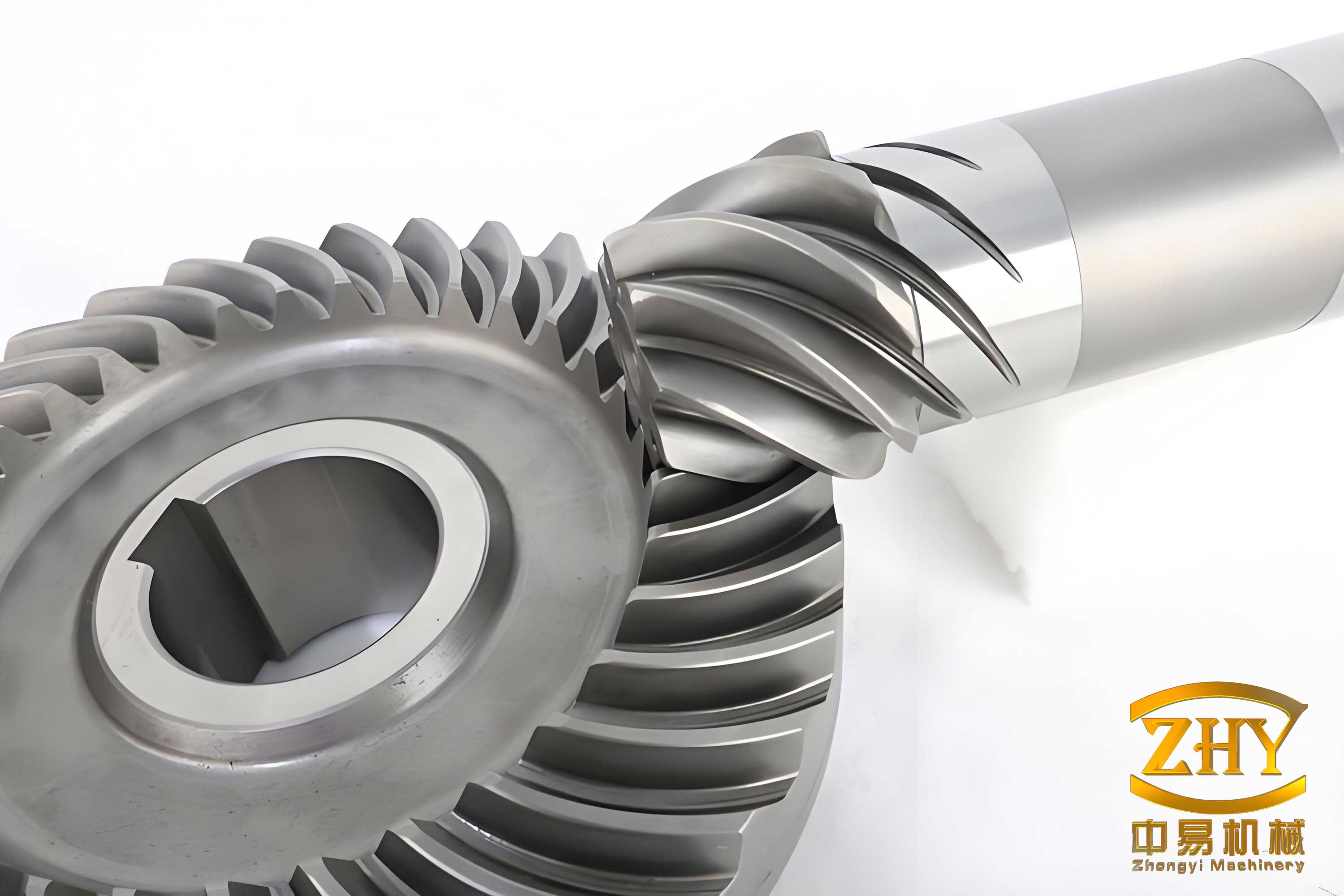
In modern mechanical engineering, the spiral bevel gear stands as a critical component in power transmission systems, widely utilized in aerospace, automotive, and marine industries due to its ability to transmit motion between intersecting shafts with high efficiency and smooth operation. The performance of a spiral bevel gear is heavily influenced by its meshing behavior under load, which involves complex interactions between multiple teeth. Understanding the load distribution across contacting teeth and the resulting stress variations, particularly bending stresses at the tooth root, is essential for optimizing design, manufacturing, and operational reliability. Traditional methods often simplify these aspects, but advanced computational techniques, such as finite element analysis (FEA) combined with Loaded Tooth Contact Analysis (LTCA), offer a more accurate representation. This article delves into a detailed methodology for analyzing the spiral bevel gear meshing process, focusing on load distribution and stress calculation using a holistic finite element model. By incorporating gear flexibility and real-time contact conditions, this approach provides insights into the dynamic behavior of spiral bevel gears throughout the engagement cycle, from entry to exit. The goal is to present a robust framework that enhances the predictive capabilities for gear performance, ultimately contributing to improved durability and efficiency in applications involving spiral bevel gears.
The foundation of this analysis lies in the development of a comprehensive finite element model that accurately represents the spiral bevel gear structure. Unlike simplified models that isolate individual teeth, this model encompasses the entire gear assembly, including the hub, web, rim, and a segment of multiple teeth—typically at least three teeth to capture interaction effects. This holistic approach ensures that the flexibility of the gear body is accounted for, which is crucial for realistic load distribution. The model is constructed using parameterized elements, such as 20-node, 18-node, and 16-node isoparametric elements, to mesh the complex geometries of the spiral bevel gear. Key coordinates, including those on the tooth surface and the fillet transition region, are derived from gear meshing theory to ensure precision. Boundary conditions are applied to simulate real-world constraints: radial and axial restraints at the hub and shoulder contact areas, and radial constraints at the hub-shaft interface. This setup mimics the operational environment, allowing for accurate deformation and stress analysis. The finite element model is generated automatically via a pre-processing program, which outputs the mesh for further computation. For instance, a typical spiral bevel gear model might consist of 342 elements and 1,720 nodes, providing a detailed discretization for analysis. The advantage of this model is its ability to compute tooth compliance—a measure of deformation under load—which is fundamental to LTCA. By integrating the entire gear structure, the model captures system-level effects that influence meshing behavior, making it superior to isolated tooth models for spiral bevel gear analysis.
The finite element model’s effectiveness can be summarized in terms of element types and nodal configurations, as shown in the table below:
| Component | Element Type | Number of Elements | Number of Nodes |
|---|---|---|---|
| Hub and Web | 20-node isoparametric | 120 | 600 |
| Rim | 18-node isoparametric | 85 | 425 |
| Tooth Segment (3 teeth) | 16-node isoparametric | 137 | 685 |
| Total | Mixed | 342 | 1,720 |
To compute the compliance matrix for the spiral bevel gear, a fundamental step in LTCA, we apply unit loads at nodal points on the tooth surface and analyze the resulting deformations. The compliance value, denoted as \( C_{i,j} \), represents the deformation at node \( i \) due to a unit load at node \( j \). Mathematically, this is expressed as:
$$ \delta_{i,j} = C_{i,j} P_j $$
where \( \delta_{i,j} \) is the deformation at node \( i \) from load \( P_j \) at node \( j \). When multiple loads act on the tooth surface—say, at \( M \) contact points—the total deformation at node \( i \) is the superposition of individual effects:
$$ \delta_i = \sum_{j=1}^{M} C_{i,j} P_j $$
For a tooth surface discretized into \( N \) nodes, applying unit loads sequentially yields an \( N \times N \) compliance matrix:
$$ \mathbf{C} = \begin{bmatrix} C_{1,1} & C_{1,2} & \cdots & C_{1,N} \\ C_{2,1} & C_{2,2} & \cdots & C_{2,N} \\ \vdots & \vdots & \ddots & \vdots \\ C_{N,1} & C_{N,2} & \cdots & C_{N,N} \end{bmatrix} $$
This matrix encapsulates the flexibility characteristics of the spiral bevel gear tooth under various loading scenarios. However, since spiral bevel gears typically exhibit point contact due to their curved tooth profiles, the compliance at actual meshing points must be interpolated from nodal values. Using the displacement interpolation functions of 16-node isoparametric elements, the compliance at any meshing point can be accurately approximated, ensuring high fidelity in LTCA iterations. This interpolation process is critical for capturing the true deformation behavior during gear operation, as it accounts for the continuous nature of contact along the tooth surface of the spiral bevel gear.
The load distribution in a spiral bevel gear during meshing is governed by the LTCA framework, which extends traditional Tooth Contact Analysis (TCA) by incorporating deformation effects. LTCA solves a set of equations that enforce gear meshing conditions under load: the fundamental gear kinematics equation, workpiece surface constraints, motion continuity, and force equilibrium. The compliance matrix derived from the finite element model is integrated into these equations to account for tooth flexibility. The meshing process is discretized into time increments—for example, 45 equal intervals from tooth entry to exit—and at each step, the LTCA equations are solved iteratively to determine the number of contacting teeth, their contact point coordinates, and the load share on each tooth. This iterative solution relies on the computed meshing point compliances, which enhance accuracy by reflecting real deformation patterns. The load distribution pattern for a spiral bevel gear typically shows variations as teeth engage and disengage; for instance, at high loads, multiple teeth may share the torque, reducing stress concentrations. The LTCA formulation can be summarized as:
$$ \mathbf{K} \cdot \mathbf{u} = \mathbf{F} $$
where \( \mathbf{K} \) is the stiffness matrix derived from the inverse of the compliance matrix \( \mathbf{C} \), \( \mathbf{u} \) is the displacement vector, and \( \mathbf{F} \) is the applied load vector. The contact conditions are enforced through inequality constraints, ensuring that only active teeth contribute to load sharing. This approach provides a dynamic view of load distribution, which is essential for predicting performance in spiral bevel gear systems.
Once the load distribution is determined via LTCA, the next step is to calculate the bending stresses at the tooth root of the spiral bevel gear. The stress analysis uses the same finite element model to ensure consistency. For each time increment in the meshing cycle, the contact information—including the number of meshing teeth, their coordinates, and allocated loads—is input into the finite element stress computation program. The model solves for stress fields under these loading conditions, outputting the three principal stresses and von Mises equivalent stress at each node in the tooth root region. The bending stress variation over time is then obtained by repeating this process across all increments. The maximum bending stress typically occurs at the fillet region, where stress concentration is highest, and its fluctuation during meshing reflects the dynamic load sharing among teeth. The stress calculation can be expressed using the elasticity equations:
$$ \sigma_{ij} = D_{ijkl} \epsilon_{kl} $$
where \( \sigma_{ij} \) is the stress tensor, \( D_{ijkl} \) is the material stiffness tensor, and \( \epsilon_{kl} \) is the strain tensor derived from displacements. For the spiral bevel gear, the root bending stress \( \sigma_b \) is often evaluated using the von Mises criterion to assess yield potential:
$$ \sigma_{vm} = \sqrt{\frac{1}{2} \left[ (\sigma_1 – \sigma_2)^2 + (\sigma_2 – \sigma_3)^2 + (\sigma_3 – \sigma_1)^2 \right]} $$
where \( \sigma_1, \sigma_2, \sigma_3 \) are the principal stresses. This comprehensive stress analysis helps in identifying critical regions in the spiral bevel gear that may require design modifications, such as optimized tooth profiles or material enhancements, to improve fatigue life and reliability.
To illustrate the methodology, consider a generic example of a spiral bevel gear pair used in a high-power transmission system, similar to aerospace applications. The gears are designed with standard parameters: module, pressure angle, and spiral angle tailored for efficient motion transfer. The finite element model, as described earlier, is built for both pinion and gear, with automatic mesh generation ensuring accuracy. The operating conditions include a transmitted power of 392 kW and a pinion speed of 8,780 rpm, representing demanding environments where spiral bevel gears are often deployed. The meshing cycle is divided into 45 time steps, and LTCA is performed to obtain load distribution. The results show that load sharing varies significantly during engagement; for instance, at peak load, up to three teeth might be in contact, distributing the torque more evenly. The load distribution curve typically exhibits a parabolic shape, with loads peaking near the pitch point and tapering at entry and exit. This behavior underscores the importance of multi-tooth contact in spiral bevel gears for reducing stress peaks.
The stress computation reveals the temporal variation of bending stresses at the tooth root. For the pinion in this spiral bevel gear pair, the maximum von Mises stress at a critical node fluctuates over the meshing cycle, as summarized in the table below for selected time steps. The stresses are normalized to the maximum observed value to highlight trends:
| Time Step (Normalized) | Number of Contacting Teeth | Load Share on Pinion (%) | Max Bending Stress (Normalized) |
|---|---|---|---|
| 0.1 (Entry) | 2 | 40 | 0.65 |
| 0.3 | 3 | 30 | 0.45 |
| 0.5 (Pitch Point) | 2 | 60 | 1.00 |
| 0.7 | 3 | 35 | 0.55 |
| 0.9 (Exit) | 1 | 100 | 0.80 |
This table illustrates how load distribution affects stress levels in the spiral bevel gear. At the pitch point, where a single tooth often bears higher loads, the bending stress peaks, while multi-tooth contact at other phases reduces stress. The finite element model confirms that the root stress varies cyclically, with the maximum value aligning with high load concentration. Such insights are vital for designing spiral bevel gears with enhanced durability, as they guide decisions on tooth geometry, material selection, and heat treatment processes. Furthermore, the compliance-based LTCA approach ensures that these predictions are realistic, accounting for system flexibility that simpler models might ignore.
In conclusion, the integration of a holistic finite element model with Loaded Tooth Contact Analysis provides a robust method for analyzing load distribution and stress calculation in spiral bevel gears. This approach captures the dynamic meshing behavior by incorporating gear body flexibility, accurate compliance matrices, and iterative LTCA solutions. The results demonstrate that spiral bevel gears exhibit complex load-sharing patterns, with multiple teeth often engaged to mitigate stress concentrations. The bending stress at the tooth root varies significantly during the meshing cycle, highlighting the need for comprehensive analysis in design phases. Key advantages of this methodology include improved accuracy over traditional isolated-tooth models, better prediction of real-world performance, and insights for optimizing spiral bevel gear systems in high-demand applications. Future work could explore effects of manufacturing errors or thermal loads, but the current framework sets a strong foundation for advancing spiral bevel gear technology. Ultimately, this contributes to more reliable and efficient power transmission systems, where spiral bevel gears play a pivotal role.