
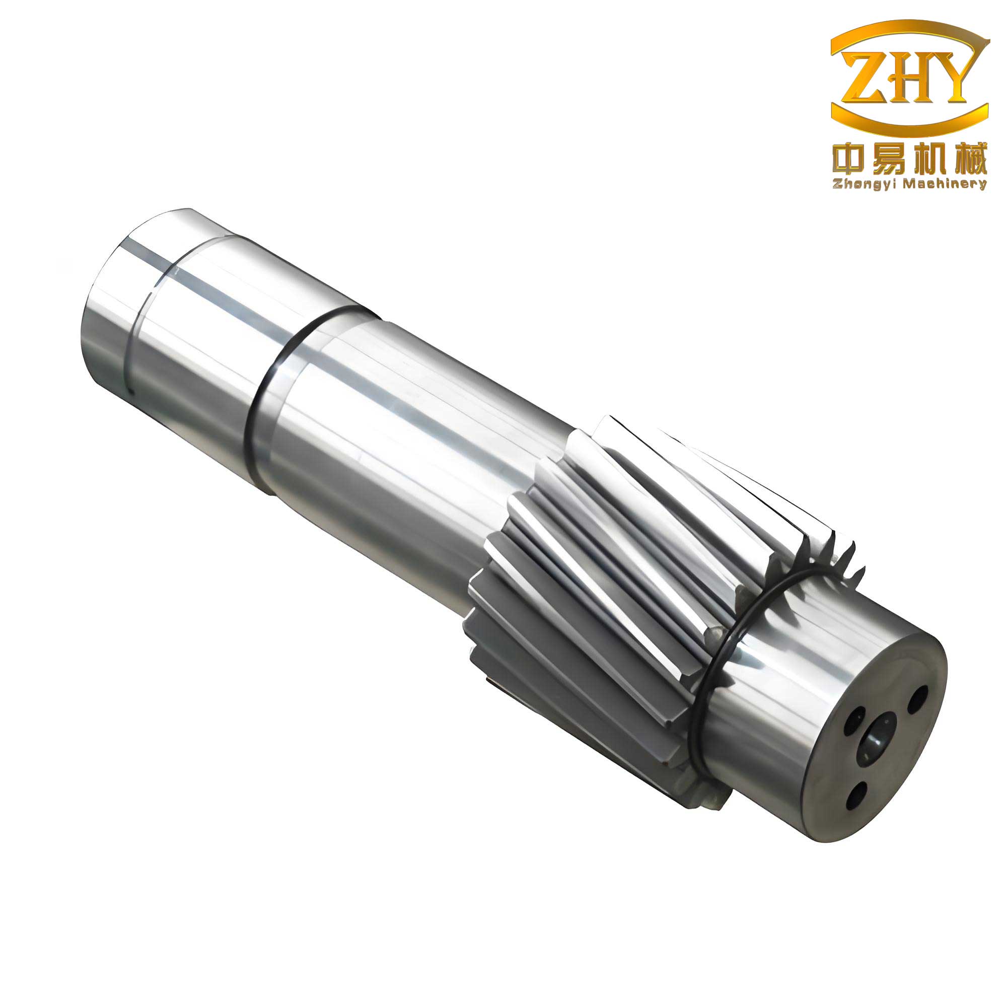
In my experience with heavy machinery manufacturing, the integrity of critical components like the output gear shaft is paramount. This gear shaft, typically used in high-torque transmission systems, must withstand rigorous operational stresses. Recently, during routine inspection after heat treatment, a crack was discovered on an output gear shaft made from 18CrNiMo7-6 steel. This incident prompted a thorough investigation to determine the root cause and prevent future occurrences. The gear shaft in question had a toothed section with dimensions of φ238mm × 130mm and a total length of 505.5 mm. The manufacturing process involved several steps: cutting, forging, normalizing, rough machining, quenching and tempering, finish machining, gear cutting, carburizing and quenching, splining, and finally gear grinding. The heat treatment protocol for this output gear shaft included carburizing at 920°C with a carbon potential of 1.1%, followed by a diffusion phase at 920°C with 0.90%C, and then quenching from 820°C with 0.75%C into oil at 80°C. A secondary quenching was performed at 810°C with 0.75%C for 6 hours, oil-cooled at 60°C, and finally tempered at 220°C for 10 hours, followed by air cooling. Out of a batch of 12 output gear shafts processed together, only one exhibited a crack after carburizing and tempering, while the others passed ultrasonic testing without defects.
The crack on the output gear shaft was visually striking. It ran longitudinally from the small end face to the large end face of the gear section, spanning approximately 390 mm in length. The crack width varied, being widest at the small end face (about 2 mm) and tapering toward the gear end. In cross-section, from the small end face (diameter φ110 mm), the crack extended radially inward for about 68 mm, with its width decreasing from the surface to the core. Additionally, a fine axial crack about 7 mm long was observed on the outer diameter, 21 mm from the small end face and 70 mm away from the main longitudinal crack. To analyze this failure, samples were extracted from the gear shaft: one from near the crack at 15 mm from the small end face (20 mm thick), and another from a tooth section (20 mm thick) for comparative study.
Macroscopic examination of the crack revealed multiple distinct zones on the fracture surface. The crack initiation site, labeled Zone I, exhibited a relatively flat surface with oxide scales, accounting for about 8.3% of the total fracture area. This indicated that the initial cracking occurred prior to the high-temperature tempering process. Adjacent to this, Zone II showed classic river patterns characteristic of crack propagation, covering 18.3% of the area. Zone III, the largest at 43.3%, displayed an exceptionally flat surface, suggesting a secondary crack initiation event. Zone IV, comprising 28.3%, exhibited radial patterns marking the propagation of this secondary crack. Zone V was the freshly broken section during sampling. The presence of oxide scales in Zone I confirmed that the crack originated before or during the carburizing process, while the morphology of other zones pointed to subsequent growth during quenching.
To quantify material properties, hardness measurements were taken across the crack sample and the tooth sample. The hardness profile from the surface to the core near the crack showed lower surface hardness due to the application of anti-carburizing coating, which reduced cooling rates. In contrast, regions adjacent to the crack exhibited higher hardness because of carburization. The tooth sample showed a typical case-hardened profile with high surface hardness and lower core hardness. The data are summarized in the following tables:
| Position on Crack Sample (Side A) | Distance from Surface (mm) | Distance from Crack (mm) | Hardness (HRC) |
|---|---|---|---|
| Point 1 | 2.4 | 30.0 | 38.4 |
| Point 2 | 6.0 | 27.5 | 43.3 |
| Point 3 | 9.8 | 24.3 | 48.3 |
| Point 4 | 13.8 | 21.2 | 48.3 |
| Point 5 | 17.4 | 19.4 | 46.3 |
| Point 6 | 22.0 | 17.0 | 46.1 |
| Point 7 | 27.5 | 14.5 | 42.1 |
| Point 8 | 32.0 | 11.2 | 43.6 |
| Point 9 | 38.0 | 6.3 | 53.0 |
| Point 10 | 44.0 | 4.3 | 54.2 |
| Position on Crack Sample (Side B) | Distance from Surface (mm) | Distance from Crack (mm) | Hardness (HRC) |
|---|---|---|---|
| Point 1 | 3.7 | 37.3 | 35.7 |
| Point 2 | 8.4 | 32.6 | 37.6 |
| Point 3 | 13.3 | 28.5 | 45.4 |
| Point 4 | 19.6 | 24.0 | 47.0 |
| Point 5 | 22.4 | 20.7 | 44.2 |
| Point 6 | 26.7 | 16.6 | 43.8 |
| Point 7 | 31.5 | 12.6 | 43.7 |
| Point 8 | 37.2 | 8.1 | 44.5 |
| Point 9 | 41.0 | 4.9 | 50.6 |
| Point 10 | 45.0 | 2.7 | 53.9 |
| Position on Tooth Sample | Distance from Tooth Top Surface (mm) | Hardness (HRC) |
|---|---|---|
| Point 1 | 6.6 | 42.0 |
| Point 2 | 10.0 | 40.9 |
| Point 3 | 13.3 | 39.6 |
| Point 4 | 16.8 | 39.0 |
| Point 5 | 20.4 | 38.2 |
| Point 6 | 24.0 | 38.7 |
| Point 7 | 27.3 | 37.7 |
| Point 8 | 30.7 | 36.7 |
The surface hardness of the tooth sample was 58-59 HRC, while the core hardness was 38 HRC. This gradient is typical for carburized gear shafts. The effective case depth on the crack sample was measured at 2.20 mm, and on the tooth sample at 2.15 mm, with carbide rating at level 1, martensite at level 2, and retained austenite below 20%. Microstructural analysis of the crack region revealed a carburized layer at the initial crack site, consisting of fine needle martensite, retained austenite, and minor carbides, transitioning to lath martensite inward. This confirms that the crack existed before carburizing. The secondary crack zones showed lath martensite without carburization or decarburization, indicating they formed during or after quenching. Crucially, metallographic examination of transverse and longitudinal sections near the crack exposed significant non-metallic inclusions, appearing as elongated stringers in the longitudinal direction. These inclusions act as stress concentrators and likely initiated the crack.
Chemical composition analysis of the output gear shaft material was conducted to ensure conformity with standards. The results, compared to EN-10084 specifications for 18CrNiMo7-6 steel, are shown below:
| Element | Standard Requirement (wt.%) | Measured Value (wt.%) | Status |
|---|---|---|---|
| C | 0.15-0.21 | 0.19 | 合格 |
| Si | 0.15-0.40 | 0.26 | 合格 |
| Mn | 0.6-0.9 | 0.56 | 合格 |
| P | ≤0.014 | 0.013 | 合格 |
| S | ≤0.003 | 0.002 | 合格 |
| Cr | 1.5-1.8 | 1.58 | 合格 |
| Mo | 0.25-0.35 | 0.28 | 合格 |
| Ni | 1.4-1.7 | 1.49 | 合格 |
All elements were within specified limits, ruling out material composition as a direct cause. However, the presence of inclusions, despite acceptable chemistry, highlights the importance of microcleanliness in steel quality. The crack morphology further supports this: straight cracks in non-coated areas and at the small end face with oxide scales suggest they formed during the initial quenching and tempering (quenching and tempering) process. The锯齿状 cracks in anti-carburizing coated areas and other straight cracks without oxides are extensions that occurred during carburizing quenching, driven by residual stresses and the pre-existing flaw.
To understand the failure mechanism, we can consider the stress intensity factor \( K_I \) for a crack in a cylindrical component like a gear shaft. For a surface crack under tensile stress, it can be approximated as:
$$ K_I = \sigma \sqrt{\pi a} \, f\left(\frac{a}{c}, \frac{a}{t}, \phi\right) $$
where \( \sigma \) is the applied stress, \( a \) is the crack depth, \( c \) is the half-length, \( t \) is the wall thickness, and \( f \) is a geometric factor. During quenching, thermal gradients induce high tensile stresses on the surface. If inclusions are present, they act as stress raisers, reducing the fracture toughness. The critical stress intensity factor \( K_{IC} \) for 18CrNiMo7-6 steel at room temperature is around 60-80 MPa√m, but it decreases at elevated temperatures during heat treatment. When \( K_I \) exceeds \( K_{IC} \), crack propagation occurs. The hardness gradient also contributes to stress distribution. The relationship between hardness and yield strength \( \sigma_y \) can be estimated using empirical formulas like:
$$ \sigma_y (\text{in MPa}) \approx 3.45 \times \text{HB} $$
for steel, where HB is Brinell hardness. Converting HRC to HB, the core hardness of ~38 HRC corresponds to about 350 HB, giving \( \sigma_y \approx 1200 \) MPa. The case hardness of ~58 HRC corresponds to about 650 HB, with \( \sigma_y \approx 2240 \) MPa. This mismatch in strength between case and core can lead to residual stresses during cooling. The cooling rate \( \frac{dT}{dt} \) during oil quenching influences the martensite transformation and stress development. The temperature distribution in a cylinder during quenching can be modeled by the heat conduction equation:
$$ \frac{\partial T}{\partial t} = \alpha \left( \frac{\partial^2 T}{\partial r^2} + \frac{1}{r} \frac{\partial T}{\partial r} \right) $$
where \( \alpha \) is thermal diffusivity. Rapid cooling causes surface contraction while the core is still hot, inducing tensile stresses on the surface. If inclusions are present, they nucleate cracks. Additionally, the carburizing process introduces carbon gradients, affecting transformation temperatures. The martensite start temperature \( M_s \) can be estimated using empirical relations such as:
$$ M_s (°C) = 539 – 423C – 30.4Mn – 17.7Ni – 12.1Cr – 7.5Mo $$
where element concentrations are in weight percent. For this gear shaft, with C varying from ~0.2% in core to ~0.8% in case, \( M_s \) ranges from ~300°C to ~150°C. Lower \( M_s \) in the case leads to delayed transformation, increasing tensile stresses in the core during cooling and promoting crack growth from inclusions.
In summary, the failure of this output gear shaft was a classic quench crack initiated by non-metallic inclusions. The crack likely started during the initial quenching and tempering process, as evidenced by oxide scales on part of the fracture surface. During subsequent carburizing and quenching, the pre-existing crack propagated due to thermal and transformation stresses. The inclusions, visible in metallographic samples, served as stress concentrators that lowered the effective strength of the material. While the chemical composition met standards, the microcleanliness was insufficient for this critical application. This gear shaft failure underscores the need for stringent quality control in material selection and processing. Future measures should include enhanced non-destructive testing after forging and quenching and tempering, such as magnetic particle inspection, to detect early cracks. Additionally, specifying higher cleanliness steels, e.g., with lower inclusion ratings per ASTM E45, can mitigate such risks. The design of the gear shaft should also consider stress relief steps and optimized quenching media to reduce thermal gradients. By addressing these factors, the reliability of output gear shafts in heavy-duty transmissions can be significantly improved.
To further elaborate on the analysis, let’s delve into the mechanical properties and fracture mechanics aspects. The toughness of a material is crucial for resisting crack propagation. The strain energy release rate \( G \) is related to the stress intensity factor by:
$$ G = \frac{K_I^2}{E’} $$
where \( E’ = E \) for plane stress and \( E’ = E/(1-\nu^2) \) for plane strain, with \( E \) being Young’s modulus and \( \nu \) Poisson’s ratio. For steel, \( E \approx 210 \) GPa and \( \nu \approx 0.3 \). During quenching, the stress state can approach plane strain due to constraint, making the gear shaft more susceptible to brittle fracture. The presence of inclusions reduces the effective cross-sectional area and creates local stress concentrations. The stress concentration factor \( K_t \) for an elliptical inclusion can be approximated as:
$$ K_t = 1 + 2\sqrt{\frac{a}{\rho}} $$
where \( a \) is the inclusion length and \( \rho \) is the tip radius. For sharp inclusions, \( \rho \) is small, leading to high \( K_t \) values that can exceed 10, drastically reducing the fatigue strength and fracture resistance. In the context of heat treatment, the cooling rate affects the microstructure and hardness. The continuous cooling transformation (CCT) diagram for 18CrNiMo7-6 steel shows that at the cooling rates achieved during oil quenching, the formation of martensite is expected, which is hard but brittle if not properly tempered. The tempering process at 220°C relieves some stresses but may not fully eliminate them if cracks have already initiated.
The carburizing process itself adds complexity. The carbon diffusion follows Fick’s second law:
$$ \frac{\partial C}{\partial t} = D \frac{\partial^2 C}{\partial x^2} $$
where \( C \) is carbon concentration, \( D \) is diffusion coefficient, and \( x \) is depth. The case depth is typically defined as the depth where carbon content reaches 0.4% above core. For this gear shaft, the effective case depth of ~2.2 mm is consistent with industrial standards. However, carburizing can also introduce internal oxidation and non-martensitic transformation products if not controlled, but in this case, the microstructure was acceptable. The key issue remains the pre-existing inclusions.
In practice, for high-performance gear shafts, non-destructive evaluation (NDE) is essential. Ultrasonic testing can detect internal flaws, but surface cracks may require dye penetrant or magnetic particle inspection. The crack in this gear shaft was found after heat treatment, but earlier detection could have saved cost. Statistical process control can also help: monitoring hardness distributions, case depths, and microstructure across batches can identify outliers. For instance, the hardness data from the crack sample showed anomalies near the crack, with higher hardness due to carburization into the crack faces. This can be quantified using the correlation between hardness and carbon content. An approximate relation for low-alloy steels is:
$$ \text{HRC} \approx 20 + 60 \times (C\% – 0.1) $$
for carbon contents up to 0.8%. This highlights how carburization increases hardness locally, altering stress distributions.
Finally, preventive measures for future production of similar gear shafts include: specifying steel with improved cleanliness (e.g., vacuum degassed or electroslag remelted grades), optimizing quenching parameters to reduce thermal stresses (e.g., using hotter oil or interrupted quenching), and incorporating stress-relief annealing after rough machining. Additionally, finite element analysis (FEA) can simulate temperature and stress fields during heat treatment to identify critical regions. For a cylindrical gear shaft, the von Mises stress \( \sigma_{vm} \) during quenching can be calculated as:
$$ \sigma_{vm} = \sqrt{\frac{1}{2}\left[(\sigma_r – \sigma_\theta)^2 + (\sigma_\theta – \sigma_z)^2 + (\sigma_z – \sigma_r)^2\right]} $$
where \( \sigma_r, \sigma_\theta, \sigma_z \) are radial, hoop, and axial stresses. High \( \sigma_{vm} \) near inclusions can initiate cracks. By integrating these approaches, the manufacturing process for output gear shafts can be made more robust, ensuring longevity and safety in service.
In conclusion, the crack in the 18CrNiMo7-6 steel output gear shaft was primarily caused by material inclusions that acted as stress concentrators during heat treatment. The failure analysis involved detailed examination of crack morphology, hardness profiling, microstructural analysis, and chemical composition verification. While the material met compositional standards, the presence of non-metallic inclusions led to quench cracking during the initial quenching and tempering stage, with further propagation during carburizing and quenching. This incident highlights the critical importance of material cleanliness and process control in the manufacture of high-stress components like gear shafts. Moving forward, enhanced quality assurance measures and material specifications will be implemented to prevent recurrence and ensure the reliability of our output gear shafts in demanding applications.