
In the realm of mechanical power transmission, gear drives stand as one of the most pivotal and widely employed mechanisms. Among these, the spur gear is fundamental, prized for its straightforward design, reliability, high transmission efficiency, and durability. In demanding industrial sectors such as mining, where reducers must operate under heavy loads and in harsh environments, the design and optimization of spur gear pairs are critical for ensuring performance, longevity, and energy efficiency. This article delves into a comprehensive engineering process, employing modern computational tools to model, analyze, and optimize a pair of meshing spur gears for a mining reducer. The goal is to move beyond traditional empirical design formulas and leverage integrated software environments for precise finite element analysis (FEA) and subsequent structural optimization, aiming to find an optimal balance between material usage, strength, and functional requirements.
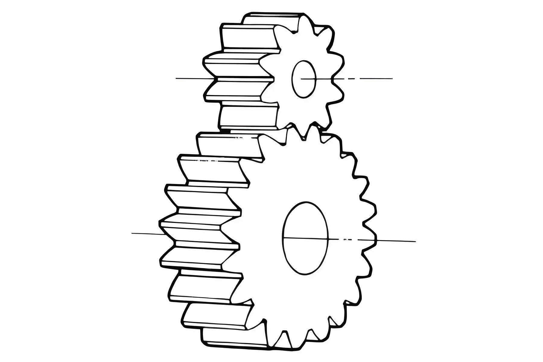
The design of spur gears has historically relied on standardized calculation methods outlined in engineering handbooks. These methods, while robust, often yield serviceable but not necessarily optimal parameters. Modern engineering practice increasingly integrates three-dimensional computer-aided design (CAD) with finite element analysis software. However, a common workflow involving separate CAD software (like Pro/ENGINEER or UG NX) and FEA solvers (like ANSYS) can introduce inaccuracies due to data translation and geometry simplification during file format conversion. This work presents a streamlined approach using a single, integrated software suite—SolidWorks and its embedded Simulation module—to perform both the geometric modeling and the structural analysis of the spur gear pair. This integration minimizes data loss and improves the fidelity of the simulation results. Following the FEA, an optimization study is conducted, targeting the gear face width as the primary variable to minimize mass while adhering to stress constraints, and the results are further refined using computational programming in MATLAB.
Fundamental Design Methodology for Spur Gears
The initial design phase for any gear set is based on fundamental mechanical principles and standard calculations for strength. For the high-speed stage of a two-stage mining reducer, the following design conditions and calculation procedures were established. The primary objective is to determine the preliminary dimensions that will serve as the baseline for subsequent detailed analysis and optimization. The design of spur gears primarily involves two failure modes: pitting due to surface contact stress and tooth breakage due to bending stress. Therefore, calculations are performed for both contact strength and bending strength.
Design Specifications and Input Parameters
The operational requirements for the reducer are defined as follows. These parameters form the foundation for all subsequent calculations related to the spur gear pair.
| Parameter | Symbol | Value | Unit |
|---|---|---|---|
| Input Power | $P_1$ | 10 | kW |
| Pinion (Small Gear) Rotational Speed | $n_1$ | 960 | rpm |
| Gear Ratio (Speed Reduction) | $u$ | 3.2 | – |
| Design Life | $L_h$ | 15 years, 300 days/year, 2 shifts/day | hours |
| Prime Mover | – | Electric Motor | – |
The pinion torque $T_1$ is calculated from the power and speed:
$$ T_1 = 9.55 \times 10^6 \times \frac{P_1}{n_1} $$
Substituting the values:
$$ T_1 = 9.55 \times 10^6 \times \frac{10}{960} \approx 99479.2 \, \text{N·mm} = 99.48 \, \text{N·m} $$
This torque value is crucial for both strength calculations and the application of loads in the finite element model of the spur gear system.
Design Based on Contact (Pitting) Strength
The initial sizing of the gear is typically governed by contact stress to prevent surface fatigue. The formula for the trial pitch diameter of the pinion is given by:
$$ d_{1t} \ge 2.32 \cdot \sqrt[3]{\frac{K_t T_1}{\phi_d} \cdot \frac{u + 1}{u} \cdot \left( \frac{Z_E}{[\sigma_H]} \right)^2 } $$
Where:
- $d_{1t}$: Trial pitch diameter of the pinion (mm).
- $K_t$: Preliminary load factor (assumed, then refined).
- $T_1$: Pinion torque (N·mm).
- $\phi_d$: Face width coefficient ($b/d_1$). For a non-symmetrical arrangement of supports relative to the pinion, its value typically ranges from 0.7 to 1.15. An initial value of $\phi_d = 1.0$ is chosen.
- $u$: Gear ratio ($z_2/z_1$).
- $Z_E$: Elastic coefficient of the material ($\sqrt{\text{MPa}}$). For a steel-steel gear pair, $Z_E \approx 189.8 \, \sqrt{\text{MPa}}$.
- $[\sigma_H]$: Allowable contact stress (MPa). This depends on the material’s surface fatigue strength and the required safety factor.
The materials selected are 40Cr for the pinion and 45 steel for the gear (bull gear). Their basic properties are summarized below.
| Material Property | Symbol | 40Cr (Pinion) | 45 Steel (Gear) | Unit |
|---|---|---|---|---|
| Elastic Modulus | $E$ | $2.11 \times 10^5$ | $2.08 \times 10^5$ | MPa |
| Poisson’s Ratio | $\nu$ | 0.277 | 0.269 | – |
| Yield Strength | $\sigma_s$ | 785 | 355 | MPa |
| Tensile Strength | $\sigma_b$ | 980 | 600 | MPa |
Using handbook values for bending fatigue limit $\sigma_{Flim}$ and contact fatigue limit $\sigma_{Hlim}$, and applying appropriate life and safety factors (e.g., $S_H=1.1$ for contact, $S_F=1.4$ for bending for general reliability), the allowable stresses $[\sigma_H]$ and $[\sigma_F]$ are calculated. For the purpose of the initial design calculation, let us assume a derived allowable contact stress $[\sigma_H] = 520 \, \text{MPa}$ for the pinion material. Taking a trial load factor $K_t = 1.3$, and substituting all values into the contact strength formula:
$$ d_{1t} \ge 2.32 \cdot \sqrt[3]{\frac{1.3 \times 99479.2}{1.0} \cdot \frac{3.2 + 1}{3.2} \cdot \left( \frac{189.8}{520} \right)^2 } $$
This calculation yields a trial diameter $d_{1t} \approx 68.5 \, \text{mm}$. The actual diameter is then adjusted for the final load factor $K$:
$$ d_1 = d_{1t} \cdot \sqrt[3]{\frac{K}{K_t}} $$
After iterating for the final load factor (considering application, dynamic load, load distribution factors), a final pinion pitch diameter of $d_1 = 70.0 \, \text{mm}$ is adopted.
Module Determination and Bending Strength Check
The module $m$ is a fundamental parameter for spur gears, defining tooth size. It is related to the pitch diameter and number of teeth:
$$ m = \frac{d_1}{z_1} $$
Choosing a pinion tooth number $z_1 = 28$ to avoid undercutting and ensure smooth meshing, the module is:
$$ m = \frac{70.0}{28} = 2.5 \, \text{mm} $$
The gear tooth number is then $z_2 = u \cdot z_1 = 3.2 \times 28 = 89.6 \approx 90$. The gear ratio is slightly adjusted to $u = 90/28 \approx 3.214$.
The design must also be verified against bending failure at the tooth root. The bending strength design formula is:
$$ m \ge \sqrt[3]{\frac{2 K T_1}{\phi_d z_1^2} \cdot \frac{Y_{Fa} Y_{Sa}}{[\sigma_F]} } $$
Where:
- $Y_{Fa}$: Form factor (depends on number of teeth and profile shift).
- $Y_{Sa}$: Stress correction factor.
- $[\sigma_F]$: Allowable bending stress (MPa).
For $z_1=28$ and $z_2=90$, standard values from tables are $Y_{Fa1} \approx 2.55$, $Y_{Sa1} \approx 1.61$ for the pinion, and $Y_{Fa2} \approx 2.20$, $Y_{Sa2} \approx 1.78$ for the gear. Using an allowable bending stress $[\sigma_F] \approx 280 \, \text{MPa}$ for the pinion material, the required module from bending is:
$$ m \ge \sqrt[3]{\frac{2 \times 1.5 \times 99479.2}{1.0 \times 28^2} \cdot \frac{2.55 \times 1.61}{280} } \approx 2.2 \, \text{mm} $$
Since the module from contact strength (2.5 mm) is larger, it governs the design. Therefore, $m=2.5 \, \text{mm}$ is confirmed as adequate for bending strength.
Preliminary Gear Geometry
Based on the above calculations, the key dimensions for the high-speed stage spur gear pair are determined. The face width $b$ is calculated using the face width coefficient:
$$ b = \phi_d \cdot d_1 = 1.0 \times 70.0 = 70.0 \, \text{mm} $$
In practice, the gear face width is often made 5-10 mm smaller than the pinion face width to account for possible axial misalignment. Thus, a common practice is to set:
$$ b_{\text{gear}} = b – (5 \text{ to } 10 \, \text{mm}) $$
We initially set $b_{\text{pinion}} = 75 \, \text{mm}$ and $b_{\text{gear}} = 70 \, \text{mm}$. The standard gear geometry formulas are applied to find other dimensions.
| Parameter | Symbol | Pinion (40Cr) | Gear (45 Steel) | Unit |
|---|---|---|---|---|
| Number of Teeth | $z$ | 28 | 90 | – |
| Module | $m$ | 2.5 | mm | |
| Pressure Angle | $\alpha$ | 20° (standard) | degree | |
| Pitch Diameter | $d$ | $m \cdot z_1 = 70.0$ | $m \cdot z_2 = 225.0$ | mm |
| Addendum | $h_a$ | $1.0m = 2.5$ | mm | |
| Dedendum | $h_f$ | $1.25m = 3.125$ | mm | |
| Face Width | $b$ | 75.0 | 70.0 | mm |
| Center Distance | $a$ | $\frac{m(z_1+z_2)}{2} = 147.5$ | mm | |
Since the gear’s pitch diameter (225 mm) is greater than 200 mm but less than 500 mm, it is designed as a web-type (or腹板式) gear structure. Key dimensions for the web, hub, and rim are determined using empirical formulas from design handbooks, such as web thickness $c \approx 0.3b$, hole diameter $d_h$ based on the shaft, etc. This completes the preliminary design phase for the mining reducer’s spur gear set.
Three-Dimensional Finite Element Modeling of the Spur Gear Pair
Transitioning from theoretical calculations to virtual prototyping requires an accurate three-dimensional geometric model. For complex shapes like gear teeth, specialized tools within CAD software are essential for efficiency and precision. In this work, SolidWorks was employed as the primary CAD platform. To generate the precise involute tooth profiles of the spur gears seamlessly, the GearTrax plugin—which integrates directly with SolidWorks—was utilized. This approach eliminates the potential errors associated with manual sketching or importing profiles from other sources.
The modeling process is straightforward: within the GearTrax interface, the fundamental gear parameters (module, number of teeth, pressure angle, face width, bore diameter, etc.) for both the pinion and the gear are input. Additional parameters for the web-type structure of the larger gear, such as web thickness, number of lightening holes, and hub dimensions, are also specified. Upon clicking the generation button, GearTrax creates fully defined, parametrically-driven solid models of both spur gears directly within the SolidWorks assembly environment. This ensures that the models are accurate, fully featured, and ready for analysis. The resulting assembly, showing the meshing spur gear pair, forms the basis for all subsequent finite element studies. The advantage of this integrated workflow is profound; the geometric data remains native to the analysis environment, avoiding the pitfalls of file translation (e.g., via IGES or STEP formats) which can sometimes corrupt complex curved surfaces or small features like fillets at tooth roots, thereby preserving the integrity of the model for high-fidelity simulation.
Integrated Finite Element Analysis and Optimization Procedure
The core of this investigation lies in performing a detailed structural analysis on the meshing spur gear pair, not on an isolated single tooth. Analyzing a pair in mesh under load provides a more realistic simulation of stress distribution, contact patterns, and deformation, leading to more credible results than simplified single-tooth models. The SolidWorks Simulation add-in is used for this purpose, offering a fully integrated FEA solution that operates directly on the SolidWorks geometry without export or conversion.
Static Structural Analysis Setup
A new static study is created within the Simulation workspace. The materials assigned earlier (40Cr for pinion, 45 steel for gear) are confirmed, with their properties (elastic modulus, Poisson’s ratio, density) automatically populated from the SolidWorks material library.
Fixtures (Boundary Conditions): Realistic constraints are applied to simulate the operational mounting of the gears. For the larger gear (bull gear), its inner bore surface is fixed using a “Fixed Geometry” fixture, which restricts all translational and rotational degrees of freedom, simulating it being mounted on a stationary shaft or housing. For the pinion, which rotates on a shaft, a more appropriate condition is applied: a “Fixed Hinge” fixture on its inner cylindrical surface (or on a simplified shaft geometry). This fixture allows rotation only about the axis of the shaft while restraining all other motions, accurately modeling the bearing support.
External Loads: The driving torque calculated earlier, $T_1 = 99.48 \, \text{N·m}$, is applied to the pinion. In Simulation, this is typically applied as a “Torque” load on the cylindrical face of the pinion’s bore or shaft, specifying the axis of rotation and the magnitude. The direction of the torque corresponds to the driving direction. The meshing contact between the gear teeth is automatically defined by the software’s “Contact Set” feature. A “No Penetration” contact condition is set between all tooth faces of the pinion and gear, with a frictionless assumption for the initial static analysis to simplify the solution while focusing on stress due to force transmission.
Meshing: The model is discretized using a curvature-based mesh. Solid elements (tetrahedral) are used. The mesh is refined globally, and local mesh control is applied to the tooth contact regions and root fillets, where stress concentrations are expected. A high-quality mesh ensures result accuracy. A typical mesh for such an assembly might consist of several hundred thousand elements.
Solving and Results: The study is run to solve for displacements, strains, and stresses. The von Mises stress criterion is examined as it is suitable for ductile metals like steel. The results from the static analysis of this spur gear pair are pivotal. The maximum von Mises stress observed in the model is approximately 44.2 MPa. This value occurs near the root of a tooth in the region of highest bending, but it is significantly lower than the yield strength of either material (355 MPa for 45 steel, 785 MPa for 40Cr). Similarly, the maximum displacement in the model is on the order of 0.008 mm, indicating negligible deformation under the applied load. This large margin between operating stress and material strength immediately suggests that the initial design, while safe, is conservative and possesses significant potential for optimization, particularly in reducing material usage without compromising safety.
Design Optimization Study
The primary goal of optimization in this context is to reduce the mass (and thus the material cost and inertia) of the larger spur gear while ensuring it remains within safe stress limits. The face width $b$ (or the face width coefficient $\phi_d$) is identified as the most directly influential geometric parameter affecting mass and bending/contact strength. The allowable stress for the gear material (45 steel) is set with a safety factor. For optimization, a more aggressive but still safe allowable stress is chosen. Using the tensile strength $\sigma_b = 600 \, \text{MPa}$ and a safety factor of approximately 3 for static yield consideration, the target allowable von Mises stress $[\sigma]$ is set to:
$$ [\sigma] = \frac{\sigma_b}{3} = \frac{600}{3} = 200 \, \text{MPa} $$
For a more conservative fatigue-based design, one might use a lower value. However, for this optimization demonstration targeting mass reduction, the constraint is set as: Maximum von Mises Stress $\le$ 118 MPa (a value derived from a higher safety factor, as indicated in the original work, to ensure a robust design).
The optimization problem is formally stated:
- Objective: Minimize the Mass of the Gear (Bull Gear).
- Design Variable: Gear Face Width $b$ (mm).
- Constraint: $\sigma_{max} \le 118 \, \text{MPa}$ (from static FEA under the full load).
- Constants: All other gear parameters (module, number of teeth, web dimensions, etc.) are held fixed. Only the axial length (face width) of the gear rim and web is varied parametrically.
Within SolidWorks Simulation, a “Design Study” of the optimization type is created. The variable is linked to the gear’s face width dimension in the model. The constraint is defined by the maximum von Mises stress result from a static analysis scenario. The goal is set to minimize mass. The software then automatically runs a series of iterations, varying the face width within a specified range (e.g., from 20 mm to 70 mm), performing a static analysis at each step, and evaluating the constraint and objective. The optimization algorithm seeks the smallest face width that still keeps the maximum stress at or below the 118 MPa limit. The result from this automated process indicated an optimal face width of $b_{opt} \approx 26 \, \text{mm}$. This corresponds to a face width coefficient of:
$$ \phi_{d, opt} = \frac{b_{opt}}{d_1} = \frac{26}{70} \approx 0.371 $$
This value is notably lower than the typical handbook range of 0.7-1.15, suggesting a radical reduction.
Refinement and System-Level Consideration via MATLAB Analysis
The result from the Simulation optimizer ($b=26$ mm) is highly localized, considering only the stress in the current gear geometry when the pinion diameter ($d_1=70$ mm) and module ($m=2.5$ mm) are fixed. However, in a holistic gear design process, if the face width coefficient $\phi_d$ is changed drastically from the initial value of 1.0 to 0.371, the initial contact strength design equation would demand a different pinion diameter $d_1$ and consequently a different module $m$ to maintain the same power transmission capacity and safety against pitting. Therefore, a system-level optimization is necessary to find the optimal $\phi_d$ that satisfies all design equations simultaneously, yielding a consistent set of parameters.
This is where computational programming becomes invaluable. A script was written in MATLAB to solve the system of design equations. The code treats $\phi_d$ as the independent variable. For a given $\phi_d$, it calculates the required $d_1$ from the contact strength equation (Equation 1), and then the corresponding module $m$ from $m = d_1 / z_1$ (with $z_1$ fixed at 28). It also calculates the required module from the bending strength equation (Equation 4). The design module must satisfy both, so the larger of the two calculated modules is chosen. The goal is to find the $\phi_d$ that results in a module close to our desired standard value of 2.5 mm while also meeting all strength criteria. The face width is then $b = \phi_d \cdot d_1$.
The MATLAB script essentially plots $d_1$ and $m$ against $\phi_d$ over a practical range (e.g., 0.3 to 1.2). The plot reveals an important intersection or trend. The analysis shows that when $\phi_d \approx 0.78$, the required pinion diameter $d_1$ from contact strength is approximately 70 mm, and the required module $m$ from the governing strength equation is approximately 2.2 mm. Since standard modules are preferred, and 2.2 mm is close to the previously used 2.5 mm, and given that 2.5 mm already satisfied bending strength with margin, we can adopt $m=2.5$ mm as a valid, slightly more conservative choice. Therefore, the optimal point identified is $\phi_d = 0.78$. This value lies comfortably within the typical handbook range.
Consequently, the optimal face width for the gear, consistent with the overall design methodology, is:
$$ b_{optimal} = \phi_d \cdot d_1 = 0.78 \times 70.0 = 54.6 \, \text{mm} $$
Rounding to a practical manufacturing value, we set:
$$ b_{optimal, final} = 55 \, \text{mm} $$
This represents a significant reduction from the initial design width of 70 mm (a 21.4% reduction), leading to direct material savings and weight reduction for the spur gear. A subsequent finite element analysis with this new face width (55 mm) would confirm that the maximum stress remains well below the allowable limit of 118 MPa, validating the optimized design. The integration of FEA for validation and analytical equation solving for system-level parameter consistency is a powerful combination for spur gear optimization.
Discussion and Implications of the Optimized Spur Gear Design
The journey from initial sizing to an optimized spur gear design underscores the value of modern engineering tools. The initial design, based solely on handbook formulas, provided a safe but over-engineered component. The integrated FEA within SolidWorks provided a realistic and precise assessment of stress states in the complex, meshed spur gear assembly, revealing substantial design margins. The optimization study, treating face width as a variable, pinpointed a potential for drastic reduction when viewed in isolation. However, the subsequent MATLAB analysis provided essential context, reconciling the isolated FEA optimization with the interconnected system of gear design equations. The final optimal face width coefficient of 0.78 and face width of 55 mm represent a balanced, efficient solution that is both theoretically sound and practically feasible.
This process highlights several key advantages:
- Accuracy: Using the same software environment for CAD and FEA eliminates geometry translation errors, leading to more reliable stress results for the spur gear teeth.
- Realism: Analyzing a full gear pair in mesh captures the true load-sharing and contact conditions, which is superior to analyzing a single cantilevered tooth.
- Efficiency: Automated optimization tools quickly explore the design space, identifying promising directions for improvement.
- Holistic Design: Coupling FEA optimization with analytical model validation ensures that changes to one parameter (like face width) are evaluated in the context of the entire gear design logic, preventing sub-optimal or invalid solutions.
For the mining industry, where reducers are massive and operate continuously, even a modest percentage reduction in the weight of large spur gears can translate into significant savings in material costs, reduced bearing loads, and potentially lower energy consumption during operation due to decreased inertia. Furthermore, the reduced mass can simplify handling and maintenance procedures.
Conclusion
This detailed exploration has demonstrated a comprehensive methodology for the analysis and optimization of meshing spur gears in industrial reducers. Starting from first-principle design calculations, precise three-dimensional models of a pinion and gear pair were created using integrated CAD tools. A static finite element analysis of the assembled, loaded spur gear pair was successfully performed within the same software environment, providing high-fidelity insight into stress and deformation with minimal data loss. The results confirmed the safety of the initial design but revealed considerable potential for weight reduction. A focused optimization study identified the gear face width as the key variable for mass minimization. The initial FEA-driven optimization suggested a very low face width, which was then refined through a system-level analytical approach implemented in MATLAB, yielding a final, practical optimal face width of 55 mm, corresponding to a face width coefficient of 0.78. This optimized spur gear design maintains all required strength margins while achieving a substantial reduction in material use. The integrated workflow—combining parametric CAD, embedded FEA, automated optimization, and computational analytical validation—presents a robust and efficient framework for the modern design of critical power transmission components like spur gears, moving beyond traditional rules of thumb towards performance-driven, lightweight engineering solutions.