
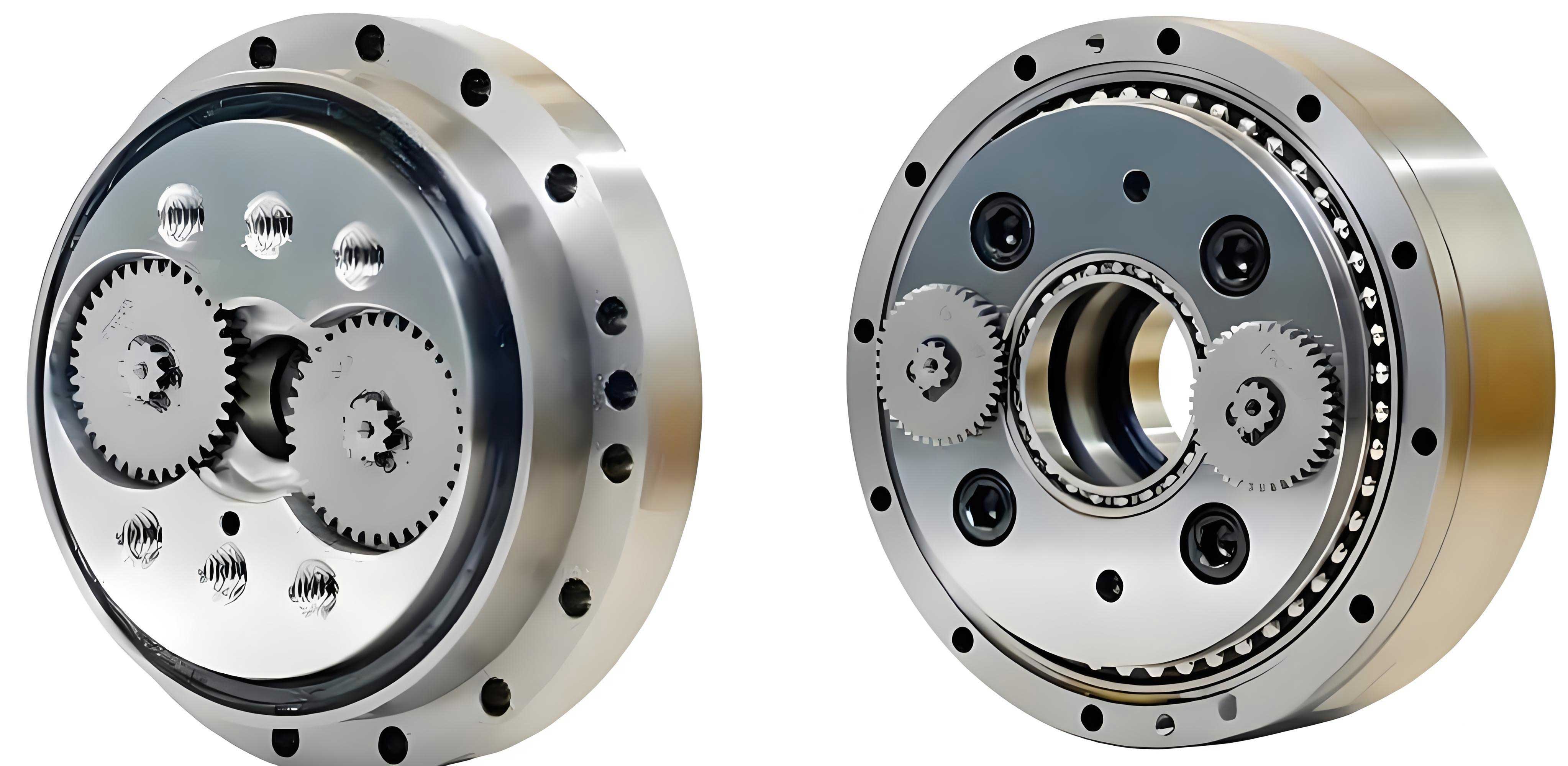
In the realm of precision power transmission, the rotary vector reducer stands as a critical component, extensively utilized in industrial robots, CNC machine tools, medical detection equipment, and satellite reception systems. Its operation hinges on a two-stage reduction mechanism: the first stage involves an involute cylindrical gear planetary reduction, while the second stage employs a cycloid pin-wheel planetary reduction, forming a closed differential gear train. Within this system, the cycloid wheel emerges as a pivotal element of the second stage. Typically, cycloid wheels are used in matched pairs, designated as Type A and Type B, which must work in concert to ensure the motion accuracy and stability of the rotary vector reducer. Consequently, the machining of these components demands not only exceptional individual precision but also stringent consistency between paired sets. This article, from a first-person perspective as an engineer engaged in advanced manufacturing, delves into the design of specialized process equipment for the finishing stages of cycloid wheel production. The goal is to enhance both accuracy and consistency through innovative tooling and optimized processes, thereby addressing common challenges in the batch production of rotary vector reducers.
The core challenge in manufacturing cycloid wheels for rotary vector reducers lies in achieving micron-level tolerances and perfect pairing compatibility. Traditional methods often result in low product yield and inefficient production due to suboptimal process sequencing, inadequate machine tool stability, and the inherent deformations introduced by heat treatment. For instance, post-heat-treatment warping necessitates multiple reciprocal基准 grinding operations to achieve required flatness, and paired wheels must be painstakingly measured and matched after machining, slowing assembly. My approach centers on a holistic redesign of the finishing process flow, coupled with the development of dedicated fixtures for each operation. This integrated strategy ensures that the stringent requirements of the rotary vector reducer are met consistently. The following sections detail the optimized production sequence, the design and implementation of key tooling, and the resultant improvements in quality and throughput.
Optimization of Production Process and Infrastructure
The finishing process for cycloid wheels begins after rough machining and heat treatment, which are typically outsourced. The initial in-house step involves grinding the two end faces. However, to combat the inconsistencies caused by heat treatment, the process flow was fundamentally restructured. The revised sequence is summarized in the table below, highlighting the critical addition of a double-sided lapping operation.
| Process Step | Key Objective | Baseline Requirement | Optimized Feature |
|---|---|---|---|
| Surface Grinding (Face Grinding) | Establish a flat datum plane. | Parallelism ≤ 0.02 mm (often requiring multiple passes). | Use of a specialized clamping fixture to minimize bending stress, enabling single-pass grinding per side. |
| Double-Sided Lapping | Achieve final thickness, parallelism, and surface quality for paired sets. | Not typically included. | Simultaneous machining of both faces on multiple wheels, ensuring height consistency within a matched pair. |
| Boring & Honing of Bearing Mount Holes | Machine three eccentric bearing bore holes with high positional accuracy. | Single-wheel processing, leading to pair mismatch. | Simultaneous machining of a matched pair (A & B) in a single fixture setup. |
| Tooth Profile Grinding | Final precision grinding of the cycloidal tooth form. | Single-wheel grinding based on bore hole datum. | Multi-wheel grinding using a high-precision hydraulic expansion mandrel fixture. |
The success of this process is heavily dependent on the production environment and equipment. To meet the extreme precision demands of the rotary vector reducer, investment in high-grade machinery is non-negotiable. This includes the procurement of imported cylindrical grinders, surface grinders, CNC boring machines, and coordinate measuring machines (CMM). Furthermore, environmental stability is paramount. Therefore, production is conducted within a temperature-controlled clean room maintained at 22 °C ± 0.5 °C. This eliminates thermal drift in machine tools and workpieces, forming a stable foundation for achieving consistent sub-micron accuracies essential for the reliable performance of the rotary vector reducer.
Design and Implementation of Specialized Process Equipment
The heart of this methodology lies in the custom-designed fixtures for each operation. These fixtures are engineered to align with the optimized process, ensuring precise locating, minimal distortion during clamping, and efficient batch processing.
Surface Grinding Fixture
Direct magnetic chucking of the heat-treated cycloid wheel for face grinding often exacerbates or fails to correct inherent warpage. To solve this, a modified three-jaw chuck fixture was developed. Standard jaws are replaced with custom jaws contoured to contact the cycloid tooth profile. The workpiece is clamped such that each jaw’s arcuate surface contacts at least two teeth, distributing clamping force evenly around the periphery. A critical feature is the use of temporary adjustable shims placed between the wheel’s face and the chuck body. These shims allow for rapid manual adjustment to approximate planar alignment before final clamping. The clamping torque is precisely controlled to 5 N·m, sufficiently low to prevent inducing bending moments. After clamping, the shims are removed, and the first face is ground. This method ensures that when released, the ground face remains stable, allowing the second face to be ground directly against the magnetic chuck without reciprocal基准 flipping. The target parallelism after this stage is 0.01 mm. The effectiveness of this fixture can be partly analyzed by considering the bending stress induced. For a thin disc clamped at its periphery, the deflection $$ \delta $$ can be approximated by plate theory. Minimizing clamping force $$ F_c $$ reduces the stress $$ \sigma $$ and thus the elastic deformation:
$$ \sigma \propto \frac{F_c \cdot r}{t^2} $$
where $$ r $$ is the radius and $$ t $$ is the thickness. By limiting $$ F_c $$, we ensure $$ \delta $$ is negligible, preserving the integrity of the ground datum.
Fixture for Boring and Honing of Bearing Holes
This operation is crucial for establishing the geometric relationship between the three eccentric bores in the paired cycloid wheels. The primary innovation is a fixture that holds the Type A and Type B wheels together in their exact operational orientation. As illustrated in the textual description, when the eccentric bores are aligned, the cycloid teeth of the two wheels are in a staggered, intermeshing position. The fixture uses movable positioning tongues that engage with the tooth spaces of both wheels simultaneously to lock their relative angular position. The Z-axis (axial) location is defined by the lapped end faces resting on a precision ground surface within the fixture.
The machining sequence is: Rough Boring → Finish Boring → Honing. A vital preparatory step is hardness sorting. Since cutting forces and tool wear are influenced by material hardness, a prerequisite for consistent machining within a pair is matched hardness. Each wheel’s tooth region hardness is measured using a Rockwell hardness tester. Pairs are formed only from wheels with a hardness differential of ≤ 1 HRC. These pairs are then permanently marked with a laser etcher for traceability. This meticulous pairing ensures uniform material behavior during cutting, which is critical for the final precision of the rotary vector reducer. The process parameters for honing can be summarized as follows:
| Parameter | Rough Boring | Finish Boring | Honing |
|---|---|---|---|
| Tool Type | Carbide Insert (PVD coated) | Diamond Insert | Diamond Abrasive Honing Tool |
| Cutting Speed (m/min) | 80 – 100 | 120 – 150 | 30 – 50 (Oscillatory) |
| Feed Rate (mm/rev) | 0.1 – 0.15 | 0.05 – 0.08 | Radial Expansion: 0.002 – 0.005 mm/pass |
| Target Diameter Tolerance (mm) | ± 0.02 | ± 0.005 | ± 0.0015 (H6/H7) |
| Target Positional Tolerance (mm) | φ 0.03 | φ 0.01 | φ 0.005 |
Tooth Profile Grinding Fixture and Mandrel Manufacturing
This is the most critical and complex piece of equipment, as it directly governs the final accuracy of the cycloid tooth form, the heart of the rotary vector reducer’s second-stage reduction. The fixture is based on a master mandrel that locates the workpiece via the three honed bearing bores. A hydraulic expansion system is integrated into the mandrel, allowing simultaneous clamping of multiple wheels of the same type (e.g., four Type A wheels). The mandrel’s design specifications far exceed the part’s requirements to minimize error stack-up.
The mandrel body is made from low-carbon alloy steel, heat-treated via carburizing, quenching, and low-temperature tempering. The specified hardness is 58-62 HRC on functional surfaces, with a core hardness of 30-45 HRC for toughness. Crucially, during carburizing, the areas destined for the three bore holes (and a surrounding zone of approximately hole diameter + 4 mm) are masked. This results in these regions retaining a lower, machinable hardness post-heat-treatment, which is essential for the subsequent precision boring operation. After heat treatment, the mandrel’s final geometry is achieved through a meticulous machining sequence.
The most challenging aspect is boring the three precision holes in the mandrel itself, which will later accept the hydraulic expansion sleeves. To accomplish this, a dedicated machining sub-fixture or “base” is designed. The mandrel is first precision ground on its external locating surfaces, ensuring runout relative to its center holes is ≤ 0.001 mm. It is then mounted onto this base. The base’s design is critical to prevent distortion during clamping on the boring machine. Its bottom contact surface is not a full ring but a narrow annular land (approx. 4 mm wide in the radial direction) ground to a slight concave profile. This creates a line contact with the machine table when clamped, preventing the transmission of clamping forces that could distort the mandrel body. The key dimensional relationships for the mandrel holes are defined by the following equations, ensuring the constructed circle of the three holes is concentric with the mandrel axis:
Let the mandrel’s central axis be at the origin O(0,0). The three hole centers are positioned at angles 0°, 120°, and 240° on a construction circle of radius R_c. The position vector for each hole i is:
$$ \vec{P_i} = R_c (\cos\theta_i, \sin\theta_i), \quad \text{for } i=1,2,3 \text{ and } \theta_i = 0, \frac{2\pi}{3}, \frac{4\pi}{3} $$
The requirement for the machining is that the axis of each hole, after boring, must be parallel to the central axis O, and its positional tolerance must satisfy:
$$ \text{Position Tolerance: } \Delta P_i = | \vec{P_{i,actual}} – \vec{P_{i,ideal}} | \leq 0.0015 \text{ mm} $$
$$ \text{Perpendicularity of each hole axis to the mandrel datum axis: } \leq 0.001 \text{ mm} $$
$$ \text{Concentricity of the construction circle of holes to the mandrel axis: } \leq 0.003 \text{ mm} $$
The boring is performed on a high-precision CNC machining center under strict thermal equilibrium (22°C ±1°C). After the holes are bored, the custom hydraulic expansion sleeves are precision ground to a light interference fit (approximately 0 to -0.002 mm) with the mandrel holes and gently pressed in place. The final assembly forms a rigid, high-precision grinding arbor.
Grinding Process and Auxiliary Tooling
With the cycloid wheels mounted on the grinding mandrel, the entire assembly is installed on the C-axis of a dedicated CNC profile grinding machine. The significant weight of the loaded mandrel necessitates an auxiliary support device for safe and accurate loading. This device provides coarse initial alignment and supports the mandrel just below the machine centerline (typically 0.5 mm lower) during the engagement of the machine’s live and dead centers. Once the centers are fully engaged and clamped, the auxiliary support disengages slightly, ensuring no contact during the grinding process to avoid vibration or distortion.
The grinding wheel is dressed to the exact, modified cycloid profile required for the rotary vector reducer. Dressing can be performed using a CNC-driven diamond roll or a form crush roll. The mathematical definition of the standard cycloid tooth profile, upon which modifications are applied, is given by the following parametric equations, where the generating circle of radius $$ r_g $$ rolls without slipping inside the base circle of radius $$ R_b $$:
$$ x(\phi) = (R_b – r_g) \cos\phi + r_g \cos\left(\frac{R_b – r_g}{r_g} \phi\right) $$
$$ y(\phi) = (R_b – r_g) \sin\phi – r_g \sin\left(\frac{R_b – r_g}{r_g} \phi\right) $$
Here, $$ \phi $$ is the rolling angle. For a rotary vector reducer, this basic profile is often modified through techniques like equidistant or isometric offset to optimize contact stress and backlash with the pin gear. The grinding process must accurately replicate this complex, modified curve. Post-grinding, each wheel is inspected on a CMM using a high-density point scanning strategy. The measured profile is compared against the digital nominal profile, and deviations are calculated to verify conformance to specifications, which are typically in the range of a few microns for high-performance rotary vector reducers.
Application Results and Performance Analysis
The implementation of the optimized process flow and the suite of specialized fixtures has yielded transformative results in the production of cycloid wheels for rotary vector reducers. The synergy between stable environmental conditions, high-precision machinery, and purpose-built tooling has addressed the core issues of low yield and poor consistency.
Quantitatively, the production output increased to 30 matched sets of cycloid wheels per day, a threefold improvement over the previous method. More importantly, the first-pass yield consistently exceeds 95%, a testament to the enhanced process capability. The statistical process control (SPC) data for key parameters show a dramatic reduction in variation. The following table summarizes the capability indices (Cpk) for critical dimensions before and after implementation.
| Critical Dimension | Specification Limit | Cpk (Previous Process) | Cpk (With New Tooling & Process) |
|---|---|---|---|
| Thickness of Paired Set | ± 0.005 mm | 0.85 | 1.67 |
| Parallelism of Faces | ≤ 0.01 mm | 0.78 | 1.80 |
| Bore Hole Diameter (H6) | +0.009 / 0 mm | 0.90 | 1.75 |
| Position of Three Bores (True Position) | φ 0.008 mm | 0.70 | 1.60 |
| Tooth Profile Error (Total) | ≤ 0.006 mm | 0.65 | 1.55 |
The improvement in Cpk values well above 1.33 indicates a highly capable and robust process. Furthermore, because matched pairs are processed together from the lapping stage onward—including hardness sorting, concurrent boring, and grouped grinding—the need for post-hoc selective assembly has been completely eliminated. Assembly technicians can now directly pair wheels based on their laser-etched matching codes, drastically reducing assembly time and virtually eliminating mismatches that could compromise the performance of the final rotary vector reducer. This streamlined workflow, from machining to assembly, underscores the systemic benefit of integrating process design with equipment innovation.
Conclusion
This comprehensive examination of the finishing process for cycloid wheels demonstrates that achieving the extraordinary precision required for rotary vector reducers is not solely a function of advanced machine tools. It is the result of a meticulously engineered ecosystem comprising an optimized process sequence, a stable production environment, and a family of specially designed process equipment. The surface grinding fixture eliminates stress-induced distortion, the double-sided lapping ensures dimensional harmony within pairs, the boring/honing fixture guarantees geometric congruence of eccentric bores, and the ultra-precision grinding mandrel enables the accurate replication of the complex cycloid tooth form. Each fixture is designed with the principles of precise location, minimal distortion, and batch efficiency at its core. The results speak unequivocally: significant gains in daily output, a substantial leap in product quality and consistency, and the elimination of wasteful selective assembly steps. This holistic approach to process and tooling design provides a scalable and reliable blueprint for the high-volume manufacturing of precision components like the cycloid wheel, which is indispensable for the advancing field of robotics and precision machinery where the rotary vector reducer plays a starring role. The methodologies and principles detailed here can be adapted and extended to other high-precision gear manufacturing challenges, pushing the boundaries of what is achievable in mechanical power transmission.