Introduction
Planning and constructing a multi-level and different-standard rail transit network is an important measure to promote the implementation of the national new urbanization strategy and promote the integrated development of urban agglomerations and metropolitan areas. In recent years, a new type of rail transit, mountain tooth rail, has quietly emerged in China, and government departments in many places across the country are stepping up the planning and construction of mountain tooth rail. Mountain tooth rail is a kind of mountain climbing railway with a maximum slope of 250‰~480‰, which is more than 10 times that of ordinary railways. The tooth rail train used in the mountain tooth rail needs to have strong climbing ability. The biggest difference between the tooth rail train and ordinary urban rail or intercity train is the tooth rail bogie, and the core of the tooth rail bogie is the tooth rail drive system. The performance and reliability of the tooth rail drive system are the core factors for the success or failure of the development of the tooth rail train. The tooth rail drive system is an extremely complex component, and there is currently no mature product in China, requiring new design and development. Therefore, it is necessary to conduct bench verification tests before loading the tooth rail drive system. At present, there is no professional test platform for the mountain tooth rail drive system in China. This article combines the characteristics and functional requirements of the tooth rail drive system to build a test verification platform for the tooth rail drive system, and conducts research on the performance and reliability of the tooth rail drive system.
Structure and characteristics of rack drive system
The rack drive system is based on the current mainstream urban rail vehicle wheelset drive system technology platform, using similar motor frame suspension + gearbox holding The axle structure adds a rack wheel and a rack brake device that need to cooperate with the rack in the middle of the axle, providing greater traction and braking force during operation on steep slopes. The structure mainly consists of wheel sets, axle boxes, transmission gearboxes, clutch mechanisms, drive gears, axle holding mechanisms, and band brakes It consists of the main motor, traction motor, coupling and other components.

Test platform for rack drive system
The main function of the test bench is to simulate the driving system of the rack and pinion under different operating conditions of the rack and pinion and wheel track, under different traction or braking loads, and apply certain vibration and impact excitations according to standard requirements. It can conduct type tests, routine tests, and research tests with different track gauges, different axle loads, and different speed levels, mainly including rack function tests, traction and braking characteristics tests, temperature rise tests, transmission efficiency tests, overspeed and overload tests, durability vibration and impact tests, rack and wheel track switching tests, and simulated large ramp traction and braking capacity tests.
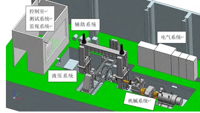
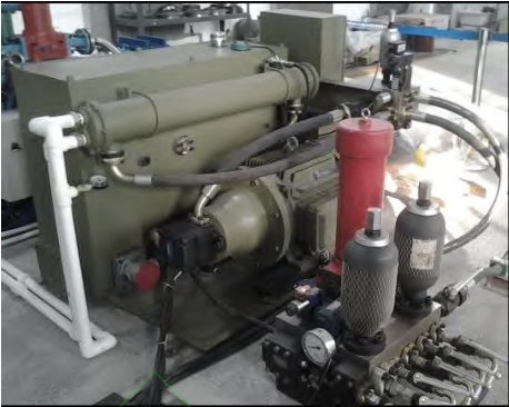
The rack drive system test bench is a rolling vibration test bench with a single wheelset and rack drive function. It uses track wheels to simulate an infinitely long rail, and uses large circular rack gears to simulate an infinitely long rack in the middle of the actual line. The test bench is vertically compressed by the simulated frame and the traction positioning devices at the front and rear to achieve longitudinal flexible positioning. The test bench is mainly composed of mechanical systems, hydraulic loading systems, electrical systems, testing and monitoring systems, and air cooling systems. The schematic diagram and overall layout of the test bench are shown in Figure 1. The power supply system of the test bench is connected to a 50Hz, 380V AC power source from the factory building, and provides power to the drive frequency converter through a circuit breaker. The inverter unit 1 of the frequency converter supplies power to the drive motor of the test bench, and the output end of the drive motor is connected to a gearbox. The gearbox is connected to the track wheel through a torque meter, serving as an adjustable torque speed load for the test bench. A large circular rack gear that is easy to disassemble is installed in the middle of the track wheel, and the upper part of the track wheel is the tested drive device. The test bench is driven by rotating the tested drive device through the track wheel or the large circular rack gear, simulating the test. The upper part of the tested drive device is equipped with a simulated frame to secure it, and the upper part of the frame is equipped with a gantry and hydraulic loading system to simulate the load of the axle weight. The front and rear of the frame are equipped with positioning devices to secure the simulated frame. During the test, the traction motor of the tested rack drive device can also be used as the main drive motor, and the inverter unit 2 can be used as the drive power source for the traction motor in the tested drive device after being boosted by a step-up transformer. By adjusting the frequency and voltage of the power supply, the traction motor can be driven to the required operating conditions, and then the tested wheelset can be used to drive the track wheel of the test bench to rotate. The motor equipped on the test bench can also be used as an electric brake motor, and the braking energy can be fed back to the grid for reuse. The vibration excitation of the test bench is achieved by processing polygons on the tested wheelset or track wheel, which can generate high-frequency vibration excitation as required by standard requirements during rotation, achieving long-life durability vibration and impact testing of the tested product with load.


Mechanical system
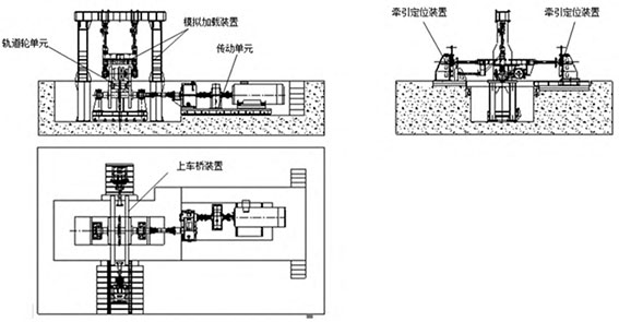
The mechanical system of the test bench is the foundation of the entire test bench, mainly consisting of track wheel units, transmission units, upper bridge devices, traction positioning devices, and simulation loading devices. The track wheel unit is used to simulate an infinitely long track and mainly consists of track wheels, track wheel shafts, large circular tooth rail gears, expansion sleeves, bearing seats, upper and lower platforms for track wheels, angle adjustment devices, oil receiving devices, etc. The track wheel bearing seat is installed on the track wheel platform, and the track wheel and track wheel shaft are connected through an expansion sleeve. By adjusting the position of the track wheel on the track wheel shaft, the track wheel gauge of the test bench can be adjusted. The large circular tooth rail gear adopts a split structure and is divided into a gear ring and a wheel core. The gear ring and wheel core are connected by bolts, and the wheel core and track wheel shaft are connected by interference fit. The gear ring adopts a two-piece assembly structure for easy disassembly and assembly. The main function of the transmission unit is to provide driving power for the track wheel unit, which is connected to the track wheel unit through a cross universal coupling. It mainly consists of a variable speed gearbox, a flywheel box, a drive motor, a transmission platform, a diaphragm coupling, a safety coupling, a universal coupling, and a torque meter.
Traction and positioning device
One set of traction positioning device is provided at the front and rear of the test drive system, which is used for longitudinal positioning. It mainly consists of a reaction frame, a traction rod, and embedded flat The traction rod can move up and down along the T-shaped slot on the mounting plate of the reaction frame to adapt to the height changes of the tested object. The tensioning force can be adjusted by extending and retracting the screw.

Simulate loading
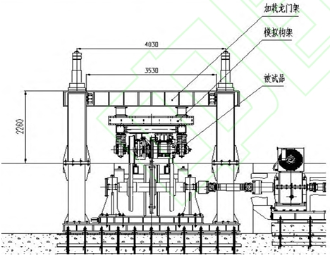
The system is used to provide support reaction force for the vertical hydraulic loading cylinder during testing and to install and fix the tested object. It mainly consists of a loading gantry and a simulation frame. The strength of the gantry is designed according to a 21t axle load, and the simulation frame adopts a movable assembly structure. Different components are connected by bolts, and different test conditions and different tested drive systems can be tested by simply replacing some parts.


Main features and technological innovation
(1) The test bench can be used for both no-load and load tests of the drive system’s wheel-rail conditions, as well as for no-load and load tests of the rack conditions,
It can also simulate the traction and braking capacity tests on the uphill and downhill of the 250‰ steep slope track of the rack rail. This technology is the first of its kind in China and fills the gap in the field of rack rail testing technology.
(2) The rack wheel installed in the middle of the track wheel of the test bench adopts a combined innovative structure of inner core + outer ring, where the inner core is an integral structure and the outer ring It is a two-part structure, designed for easy assembly and disassembly during testing. The inner core is a shrink-fit structure that is mounted on the axle, facilitating easy assembly and replacement. The gears on the outer ring have a modular design The number of teeth can be adjusted according to the diameter of the track wheel, which can adapt to various types of rack and pinion.
(3) The wheelset gauge of the test bench can be adjusted within the range of 1000-1520mm according to the needs of the tested object, and the axle load can be adjusted within the range of 12t-21t The test is adjusted to accommodate vehicle drive systems with different track gauges and axle loads.
(4) The test bench can accommodate both 750V and 1500V voltage levels for the tested drive system to conduct both idle and full-load tests, expanding the test bench’s testing adaptability and scope.
(5) The test bench has a function of electric energy feedback during testing, that is, when the test bench motor is pulling, the tested motor can implement electric braking; conversely, the tested motor can implement electric braking when the test bench motor is pulling When the machine is driven, the test bench motor can achieve braking, and the braking energy is fed back to the intermediate DC link, allowing the electric energy to continue to be utilized. According to testing, energy consumption can be saved by more than 70% during testing.
conclusion
The establishment and application of the rack drive system test bench has filled the domestic There is no blank for the test bench of the toothless rail drive, which optimizes the testing of the vehicle drive system This means that China has the necessary means to develop the rack and pinion drive system experimental study conditions. Through the study of different types of rack and pinion vehicle drive systems The test not only provides a test basis for product performance evaluation and improvement According to the report, it has also accumulated rich experience for the application of test beds.
