Introduction
As a key equipment for conveying raw coal in underground coal mines, the scraper conveyor has very high reliability requirements. The main factors affecting the reliability of the scraper conveyor are the transmission system composed of motors, couplings, reducers, sprocket shafts, and scraper chain components. The reducer is the core component of the transmission system, and due to the limited installation space and cantilever installation form, it requires a very compact structure and high strength of its box. In addition, with the increasing large-scale mining equipment, the power of the supporting motor for the planetary reducer has reached 3000kW, and some planetary reducers have begun to replace the split-type structural box with a higher strength monolithic box. The monolithic cast-formed planetary reducer box has various advantages such as compact structure, long service life, and low equipment damage rate, and has replaced some split-type box structures. However, the monolithic cast-formed box structure has difficulty in assembling components such as the input shaft and second shaft, and it is difficult to adjust the contact area of the reducer conical gear pair. The existing method for adjusting the contact area of the reducer conical gear pair in the split-type box structure is not applicable, and new installation structures and new contact area adjustment methods need to be studied.
Integrated box structure planetary reducer bevel gear pair installation structure research
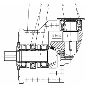
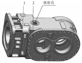
The schematic diagram of the split-type structure reducer bevel gear pair is shown in the figure. The upper and lower boxes of the split-type structure reducer can be separated. When assembling the reducer, the input shaft and the second shaft are first installed into the lower box. The outer circle ends of the four-point contact ball bearings on the input shaft and the aligning ball bearings on the second shaft, as well as the outer circle ends of the four-point contact ball bearings, are left with space for adjusting pads. The contact area of the bevel gear pair formed by the input shaft bevel gear and the second shaft bevel gear is adjusted by moving the input shaft and the second shaft along their axial direction through the input shaft and the second shaft, respectively. The thickness of the adjusting pads is determined based on the measured clearance between the outer circle sections of the relevant bearings of the input shaft and the second shaft. After assembling the components in the lower box, the upper box is assembled last. The difficulty of adjusting the contact area of the reducer bevel gear pair is relatively small. The three-dimensional diagram of the integrated box structure is shown in the figure. The input shaft and the second shaft of the reducer with an integrated box structure need to be assembled from the side of the box. If the structure of the input shaft and the second shaft cannot be adjusted according to the structural design of the split-type box reducer, it is necessary to redesign the structure and positioning method of the input shaft and the second shaft in combination with the integrated box structure.


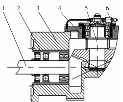
The input shaft of the integral box structure can only be installed from the bearing mounting hole on the box. The second shaft and the reducer side plate are assembled together and then assembled from the side of the box. Therefore, the input shaft and the second shaft must be designed to be able to be assembled as a whole, and can move as a whole along the axial direction. The axial positioning can only be adjusted by designing the contact area of the bevel gear pair outside the box, and observing the position of the contact area from the observation hole on the upper part of the box. Therefore, the input shaft and the second shaft are designed with bearing cups for axial positioning, and the axial positioning of the input shaft and the second shaft is designed on the bearing cups, which are positioned outside the integral box. The axial change of the bearing cup flange and the gap between the box and the reducer side plate drives the input shaft and the second shaft to move as a whole, achieving the adjustment and axial positioning of the contact area of the reducer bevel gear pair.

Key technology for adjusting the contact area of the bevel gear pair in the integrated box structure planetary reducer
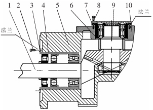
The foundation for adjusting the contact area of the bevel gear pair in the integrated box structure reducer is the overall axial movement of the input shaft and the second shaft within the box, fine-tuning the axial position of the axial positioning bearing, while the axial positioning connection of the input shaft and the second shaft is achieved by adding an adjustment pad outside the box. The input shaft and the second shaft are designed as a bearing cup structure with a connecting flange to achieve the adjustment and positioning of the axial positioning bearing. In addition, an observation hole for observing the contact area of the bevel gear pair is designed on the integrated box structure to check the position and size of the contact area during adjustment.

The input shaft adjusting pad is embedded in the cross section of the input shaft and the input shaft bearing mounting hole of the box, adjusting the feed rate of the input shaft along the axial direction. The second shaft adjusting pad is embedded in the end face of the second shaft and the second shaft bearing mounting hole of the box, adjusting the feed rate of the second shaft along the axial direction. The integrated box is designed with an observation hole, which faces the contact area of the input shaft bevel gear and the second shaft bevel gear. The installation and adjustment method of the reducer bevel gear pair is as follows:
(1) The input shaft is assembled into the box from the input shaft bearing hole of the box as a whole, and the side plates of the second shaft reducer are assembled together and then installed into the box as a whole. By adjusting the axial feed rate of the input shaft and the second shaft, the contact position and contact area of the bevel gear pair are adjusted. The contact position and contact area of the bevel gear pair are determined through the observation hole of the box;
(2) When the contact position and contact area of the bevel gear pair meet the requirements, measure the clearance formed between the flange surface of the input shaft bearing cup and the end face of the bearing hole in the box body, as well as the clearance formed between the flange surface of the second shaft bearing cup and the cross section of the bearing hole in the side plate of the reducer;
(3) Adjust the thickness of the input shaft adjusting pad and the second shaft adjusting pad based on the measured clearance, and insert the input shaft adjusting pad into the gap formed between the flange surface of the input shaft bearing cup and the end face of the bearing hole of the box. Similarly, insert the second shaft adjusting pad into the gap formed between the flange surface of the second shaft bearing cup and the end face of the bearing hole of the box. Use connecting bolts to connect and position the input shaft and second shaft bearing cup flanges with the reducer box and reducer side plate, respectively, to complete the adjustment and installation of the reducer bevel gear pair.
Epilogue
The developed high-power mining reducer has been used in the underground working face and main gate of coal mines with scraper conveyors and scraper loaders. The adjustment technology of the contact area of the planetary gear reducer’s bevel gear pair in the integrated box structure and the new structure of the components have solved the technical problems of assembling and adjusting the contact area of the main gear pair in the integrated box structure reducer, which has played a promoting role in improving the transmission efficiency of the reducer and provided a new solution for the design of the integrated box structure reducer.
