In the process of spiral bevel gear machining, the large wheel often adopts the generating method and forming method, and the small wheel often adopts the tilting method and deformation method. The large wheel is processed by generating method and the small wheel is processed by denaturing method. The shaking table mechanism of the machine tool simulates an imaginary gear, and the cutting surface of the cutter head installed on the shaking table is an imaginary gear tooth. When the wheel embryo and the imaginary tooth rotate around their respective axes with a certain transmission ratio, the cutter head will cut a tooth groove on the wheel embryo. The cutting process of a gear is like the meshing process of a pair of gears. This machining method is called generating method. In order to increase the freedom of the production wheel, the transmission ratio between the production wheel and the workpiece can be changed to adapt to the tooth surface correction of the small wheel. This method is processed on the machine tool equipped with a denaturing mechanism. This processing method is called denaturing method.
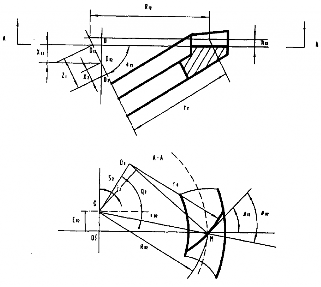
The processing of right-hand large wheel with left-hand production wheel is shown in the figure:
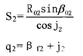
The adjustment parameters of the machine tool include the position of the cutter head relative to the forming wheel (referred to as the cutter position), the position of the large wheel relative to the forming wheel (referred to as the wheel position) and the transmission ratio between the forming wheel and the large wheel (referred to as the roll ratio). In the figure, O is the intersection of the production wheel axis and the tool tip plane, which is the center of the machine tool. OO is the intersection of the cutter head axis and the cutter tip plane, which is the cutter head center. The rear position of the cutter head relative to the production wheel can be determined by the distance S2 between OOo and the included angle Q2 between OOo and the horizontal axis. S2 is called radial tool position and Q2 is called angular tool position. If so ordered:

From the diagram:

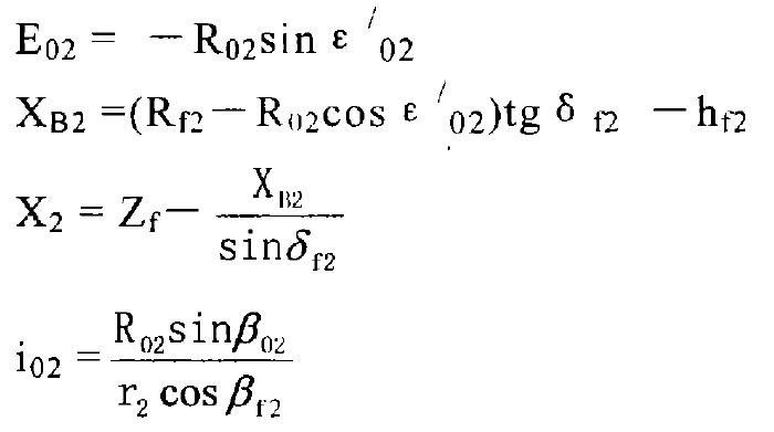
The position of the large wheel relative to the production wheel is determined by the included angle between the axis of the large wheel and the plane of the machine tool δ M2= δ F2. The offset distance E02 between the big wheel axis and the production wheel axis (hereinafter referred to as the vertical wheel position), the distance x2 between the intersection O2 of the big wheel and the cutting intersection o ‘2 (hereinafter referred to as the axial wheel position) and the distance XB2 from O02 to the plane of the machine tool (hereinafter referred to as the bed position). The following formula can be obtained from the figure:


