
Main motion transmission chain: the main motion chain to realize the rotation of gear hobbing hob: motor-1-2-uv-3-4-hob. Among them, UV can adjust the forming speed of involute profile, that is, it is an important parameter to adjust the spindle speed. Generating motion transmission chain: the compound motion composed of the rotating motion of hob and the rotating motion of machined gear is called generating motion. It uses the generating principle to make the gear form an involute. The two ends of the generative motion transmission chain are the spindle of the worktable and the hob respectively, which is the internal connection transmission chain: hob-4-5-ux-6-7-worktable. The generative motion transmission chain ensures the strict tooth splitting motion relationship between the tool and the gear blank, in which Xu is used to meet the changes of the number of teeth of the gear to be processed and the number of hob heads.
Vertical feed movement transmission chain: the hob holder moves along the column guide rail to realize the vertical feed movement of the hob. It can also realize forward milling and reverse milling in gear hobbing. As an external connection, the transmission chain is: workbench-7-8-uf-9-10-tool holder. UF can be used to adjust the feed direction and feed rate, and control the machining parameters.
Gear hobbing is not only the basic way to process cylindrical gears, but also the basic way to process surface gears. The above three transmission chains are also included in the hobbing processing of helical gear on ordinary hobbing machine, but the difference between it and the processing of general helical cylindrical gear is that the axis of the processed helical gear is not placed vertically, but placed horizontally.
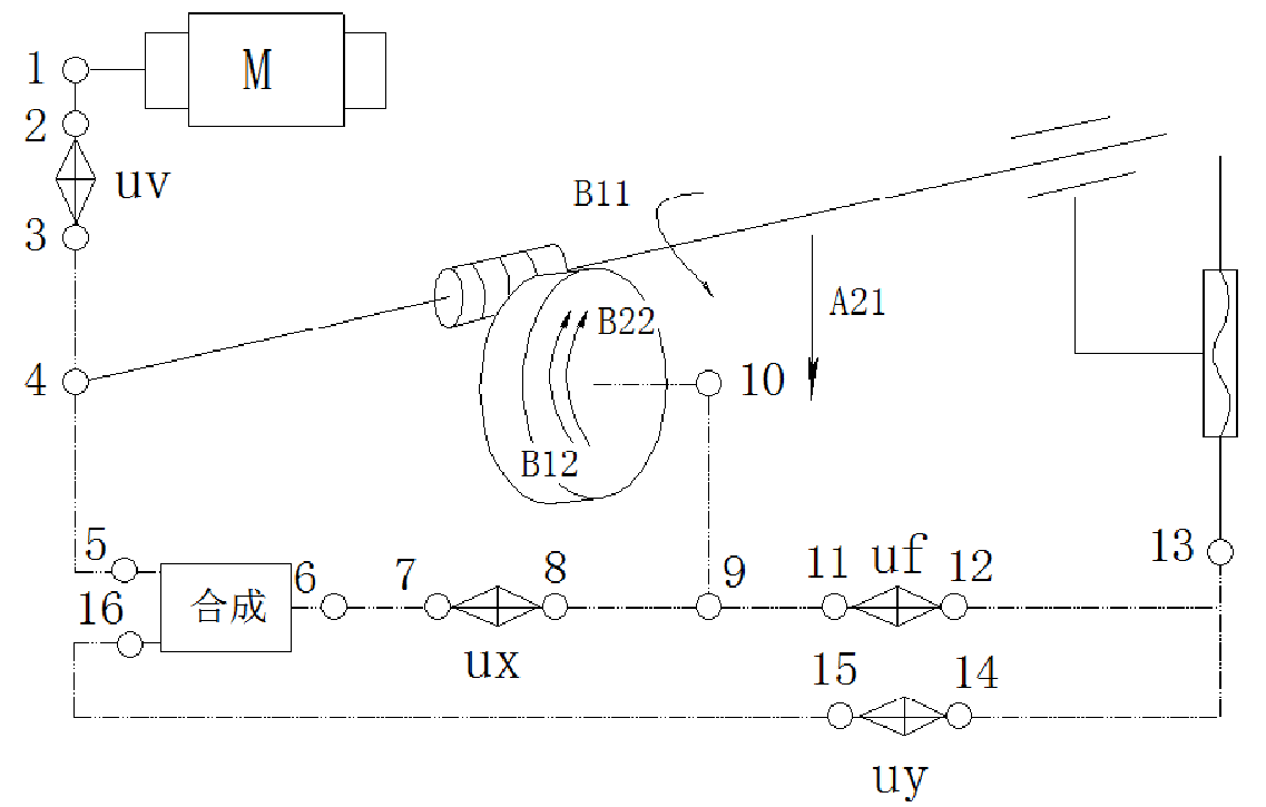
Therefore, when machining helical gear on ordinary hobbing machine, it is necessary to design a set of fixture to realize the hobbing of face gear, such as adding a bevel gear transmission with transmission ratio of 1, in order to change the direction of the axis of the workpiece and keep the transmission ratio in the original transmission chain unchanged, while the machining part of the workpiece is changed from the cylindrical surface of the cylindrical blank to the end face. The schematic diagram of transmission chain for hobbing helical gear after improvement of Y3150E hobbing machine is shown in the figure. In the improved gear hobbing machine, a pair of bevel gear pairs with transmission ratio of 1:1 are added to the generative motion transmission chain.