
I have examined the revised standard TB/T 3134—2023, Rolling Stock Driving Gearbox—General Requirements, as a practical engineering reference for the design, manufacture, verification, and inspection of driving gearboxes used on electric multiple units and locomotives. My primary interest is the way this standard consolidates two earlier documents into one coherent technical framework while preserving the functional intent of the original requirements. The driving gearbox is not a secondary component. It is the mechanical interface through which traction torque is transmitted from the traction motor to the wheelset, and every pinion gear, ring gear, bearing, seal, housing, fastener, lubricant, and suspension element contributes to the safety and reliability of the vehicle. I read the revision as a response to three forces: advances in material and manufacturing technology, higher vehicle performance demands, and the continuing modernization of the railway standards system.
The older documents covered EMU driving gearboxes and locomotive wheel-set drive systems separately. Their replacement by a single general standard is significant because it creates a common vocabulary for pinion gear design, housing strength, bearing life, lubricant selection, sealing, testing, and inspection. I find that the new standard is not merely an editorial merge. It changes operating conditions, technical limits, test methods, and inspection rules in ways that reflect actual service experience and current manufacturing practice. The pinion gear remains a central object of attention because it is the first gear in the torque path, it operates at the highest speed, and its alignment, backlash, surface integrity, and lubrication strongly influence noise, vibration, efficiency, and durability.
In my reading, the standard is best understood through a set of linked questions. What environment must the gearbox survive? What temperatures must the oil and bearings withstand? What efficiency must the mesh and bearings achieve? What materials are acceptable for the housing and the pinion gear? How should the pinion gear, bearings, seals, and fasteners be assembled? Which tests demonstrate that the complete system is safe? Which deviations require type testing? The revised standard answers these questions with clearer quantitative limits and more direct references to component-level standards. It also removes requirements that have become redundant because modern manufacturing methods already provide the intended quality.
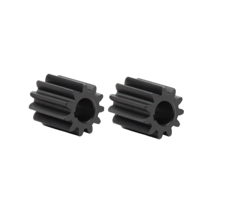
I begin with operating conditions because they determine the boundary of every subsequent calculation and test. The revised standard adds a special ambient temperature range for EMU driving gearboxes and modifies the locomotive wheel-set drive gearbox range. It also removes the gauge requirement from the general operating conditions. I interpret this as a move toward separating the gearbox envelope from vehicle-level interface constraints. The gearbox must still fit within the bogie or underframe envelope, but the general standard now concentrates on the functional conditions that directly affect the pinion gear, bearings, lubricant, seals, and housing.
| Operating condition item | EMU driving gearbox in the revised standard | Locomotive wheel-set drive system gearbox in the revised standard | My engineering note |
|---|---|---|---|
| General ambient temperature | Standard railway operating environment | -40 °C to +40 °C | The locomotive range is optimized to reflect actual service profiles. |
| Special ambient temperature | -40 °C to +40 °C | Not separately listed in the same way | This special condition supports extreme cold and high-temperature regions. |
| Previous locomotive range | Not applicable | -40 °C to +50 °C in the old standard | The upper limit is reduced to +40 °C in the revised general requirement. |
| Gauge requirement | Deleted | Deleted | Vehicle-level gauge control remains outside the gearbox general standard. |
| High-speed continuous operation | Supports sustained high-speed operation, including 350 km/h class duties | Supports locomotive traction duties | The pinion gear and bearings must survive sustained thermal and dynamic loads. |
| Sealing environment | Rain, snow, dust, and high-speed airflow | Railway underfloor environment | Sealing is treated as a performance requirement, not only a assembly detail. |
I see the temperature requirements as especially important for the pinion gear. A pinion gear running at high speed generates mesh heat and churning heat, and the lubricant must carry that heat away while maintaining a stable film. If the lubricant viscosity falls too far at high temperature, the pinion gear and bearings may experience inadequate film thickness. If the lubricant viscosity rises too high at low temperature, the pinion gear may suffer from poor oil distribution during start-up, and the bearings may experience sliding friction before a stable lubricant film forms. Therefore, I treat the operating temperature range as a direct input to lubricant selection and thermal test design.
The revised standard also changes fastening requirements. It expands the use of anti-loosening marks from important fastening locations to all fastening locations. I consider this a practical improvement because a loose fastener on a pinion gear bearing housing, inspection cover, oil plug, or suspension element can lead to oil loss, misalignment, or a safety-critical failure. The standard also requires that fasteners satisfy the relevant design rules in TB/T 3246. In addition, critical screws and bolts must have a property class not lower than 8.8, and nuts must have a property class not lower than 8. Fastener surfaces must have corrosion protection. I regard these requirements as the minimum basis for maintaining pinion gear alignment and gearbox structural integrity over repeated thermal cycles and vibration.
| Fastener requirement | Previous approach | Revised approach | Effect on pinion gear and gearbox |
|---|---|---|---|
| Anti-loosening mark | Important fastening locations | All fastening locations | Improves detection of loosening near pinion gear bearing supports and covers. |
| Design rule | Separate anti-loosening and engagement length clauses | Comply with TB/T 3246 | Creates a single design reference for fasteners. |
| Bolt property class | General requirement | Not lower than 8.8 for critical locations | Maintains preload under vibration and thermal loading. |
| Nut property class | General requirement | Not lower than 8 | Prevents thread stripping and loss of clamp load. |
| Surface protection | Implied by general corrosion protection | Explicitly required | Reduces risk of corrosion-induced preload loss. |
| Aluminum housing connection | 4.8 class tightening torque for aluminum parts | Deleted; wire thread inserts or steel thread inserts are used | Better matches actual aluminum housing practice and protects pinion gear bearing bores. |
Temperature limits are among the most visible technical changes. The revised standard replaces formula-based conversion with direct allowable temperature limits. For EMU driving gearboxes, the maximum allowable bearing temperature is not greater than 135 °C, and the maximum allowable lubricant temperature is not greater than 120 °C. For locomotive wheel-set drive system gearboxes, the maximum allowable lubricant temperature is not greater than 95 °C for mineral oil and not greater than 120 °C for synthetic oil. I find these limits easier to apply during test stand acceptance because they remove ambiguity about which temperature rise formula should be used and which reference ambient temperature should be selected.
| Thermal limit | EMU driving gearbox | Locomotive wheel-set drive gearbox | My interpretation |
|---|---|---|---|
| Maximum bearing temperature | Not greater than 135 °C | Not explicitly stated as a single value in the same clause | The pinion gear bearing and output bearing must remain below the EMU limit. |
| Maximum lubricant temperature | Not greater than 120 °C | Not greater than 95 °C for mineral oil; not greater than 120 °C for synthetic oil | Oil type and thermal stability are directly linked. |
| Temperature rise basis | Direct allowable temperature | Direct allowable temperature for oil | Reduces reliance on derived temperature-rise formulas. |
| High-temperature test | Required | Low-temperature test is emphasized | The pinion gear and oil must be evaluated under realistic thermal conditions. |
| Low-temperature test | Required | Required, with oil pour point substitution allowed when needed | Start-up behavior is critical for the pinion gear and bearings. |
Efficiency is another area where I see a deliberate move toward realistic system-level performance. The old standard used higher values that mainly reflected the gear mesh. The revised standard accounts for the entire gearbox, including gear mesh losses, bearing losses, churning losses, windage losses, and seal losses. For EMU driving gearboxes, the revised requirement is not less than 97% for a single-stage gearbox and not less than 96% for a multi-stage gearbox at rated power and rated speed. For locomotive wheel-set drive system gearboxes, the requirement is not less than 95% at rated power. I consider this more defensible because a complete gearbox cannot avoid bearing and churning losses, and the pinion gear alone does not represent the whole transmission path.
The basic efficiency relationship I use in my analysis is:
$$ \eta = \frac{P_2}{P_1} \times 100\% = \left(1 – \frac{P_V}{P_1}\right) \times 100\% $$
where \(\eta\) is the transmission efficiency, \(P_1\) is the input power, \(P_2\) is the output power, and \(P_V\) is the total power loss. I further decompose the total loss into load-dependent and load-independent terms:
$$ P_V = P_{V,mesh} + P_{V,bearing} + P_{V,churning} + P_{V,windage} + P_{V,seal} $$
For a pinion gear stage, the mesh loss and pinion gear bearing loss are especially important because the pinion gear rotates at the highest speed in the gearbox. The churning loss associated with the pinion gear and its surrounding oil volume can become significant at high speed, particularly when the oil level is high or the housing geometry allows excessive oil to be thrown by the pinion gear. The windage loss around the pinion gear and the ring gear also increases with speed. Therefore, I interpret the revised efficiency values as a compromise between theoretical gear efficiency and measured complete-gearbox efficiency.
| Efficiency item | Old requirement | Revised requirement | My assessment |
|---|---|---|---|
| EMU single-stage gearbox | Not less than 99% | Not less than 97% | More realistic because bearing, churning, windage, and seal losses are included. |
| EMU multi-stage gearbox | Not less than 98% | Not less than 96% | Recognizes additional mesh and bearing losses. |
| Locomotive wheel-set drive gearbox | Separate old requirements | Not less than 95% at rated power | Reflects complete system losses and locomotive duty cycles. |
| Test condition | Not always fully defined for complete gearbox | Rated speed and rated power; forward and reverse once each | Improves repeatability and comparability. |
| Test method | General method | GB/T 14231 for gear unit efficiency measurement | Provides a recognized measurement basis. |
The standard also strengthens material and component requirements. For housings, the revised standard distinguishes between attached or separately cast test specimens and specimens taken from the casting itself. Cast aluminum housings must comply with the relevant aluminum casting requirements, and ductile iron housings must comply with the applicable ductile iron general technical requirements. This matters because the housing supports the pinion gear bearings and maintains the center distance between the pinion gear and the ring gear. Any deformation or crack in the housing can change the mesh pattern, increase vibration, and reduce pinion gear life.
| Housing material | Specimen type | Mechanical property reference | My design note |
|---|---|---|---|
| Cast aluminum alloy | Attached or separately cast specimen | Mechanical property requirements for the material | Use when lightweight design is important. |
| Cast aluminum alloy | Specimen taken from the casting body | Class B casting requirements in TB/T 3409—2021 | Verifies actual casting quality near critical pinion gear bearing areas. |
| Ductile iron | Attached or separately cast specimen | Mechanical property requirements for ductile iron | Provides strength and stiffness for higher load cases. |
| Ductile iron | Specimen taken from the casting body | TB/T 1465 general technical conditions | Confirms local properties of the housing body. |
| Aluminum housing threads | Threaded holes | Wire thread inserts required | Protects threads and maintains clamp load around the pinion gear support. |
For the pinion gear and other gears, the revised standard refers directly to TB/T 2989 for common material grades and requirements. It also states that carburized alloy steel is preferred. I agree with this direction because carburizing produces a hard, wear-resistant surface and a tough core, which is well suited to the high contact stresses and bending loads experienced by a pinion gear. The standard requires calculation or verification of contact load capacity, bending load capacity, scuffing load capacity, and static strength. These checks are essential because a pinion gear may fail by pitting, tooth breakage, scuffing, or plastic deformation depending on the load regime.
| Gear verification item | Physical meaning | Why it matters for a pinion gear | Typical influencing factors |
|---|---|---|---|
| Contact load capacity | Resistance to surface fatigue and pitting | The pinion gear has a small number of teeth and high cycle count. | Hardness, roughness, lubrication, alignment, contact stress. |
| Bending load capacity | Resistance to tooth root fatigue fracture | The pinion gear tooth root experiences alternating bending stress. | Fillet radius, case depth, core strength, load distribution. |
| Scuffing load capacity | Resistance to adhesive wear at high sliding speed | High-speed pinion gear meshing can generate high flash temperature. | Oil type, viscosity, surface finish, sliding velocity, load. |
| Static strength | Resistance to severe short-duration load | Motor short-circuit or protection torque can overload the pinion gear. | Yield strength, tooth geometry, shaft support stiffness. |
| Backlash | Circumferential clearance between meshing teeth | Controls lubrication, noise, and load distribution of the pinion gear mesh. | Center distance, tooth thickness, thermal expansion, bearing clearance. |
The standard specifies that gear backlash must conform to the design value and be measured according to the relevant cylindrical gear inspection practice. I consider backlash a subtle but critical parameter for the pinion gear. If backlash is too small, the pinion gear may operate with insufficient lubrication clearance and may generate excessive heat. If backlash is too large, impact loading and noise may increase. Because the pinion gear and ring gear operate under different thermal expansions, the design backlash must account for the full operating temperature range.
Bearing life calculation has also been clarified. The revised standard requires that the calculated mass range for bearing life be defined. For the pinion gear shaft bearing, the calculated mass includes the pinion gear and all parts mounted on the pinion gear shaft. For the output gear shaft bearing, the calculated mass includes the gearbox mass except the output gear and all parts mounted on the output shaft, excluding the large bearing. This is a practical distinction because the pinion gear shaft usually carries the pinion gear, spacers, nuts, and sometimes a coupling element, while the output shaft is integrated with the wheelset and its mass is partly external to the gearbox calculation.
| Bearing location | Calculated mass range in the revised standard | My interpretation |
|---|---|---|
| Pinion gear shaft bearing | Pinion gear and all parts mounted on the pinion gear | The pinion gear assembly mass must be included in bearing load and life calculation. |
| Output gear shaft bearing | Gearbox mass excluding the output gear and all parts mounted on the output shaft, excluding the large bearing | The calculation focuses on the gearbox-supported mass rather than the wheelset mass. |
| Bearing clearance | Must meet assembly technical conditions | Clearance affects load distribution, temperature, and pinion gear alignment. |
| Life calculation | Must be calculated and corrected as required | Correction factors account for reliability, lubrication, and contamination. |
I often use a basic bearing life expression to frame the calculation:
$$ L_{10} = \left(\frac{C}{P}\right)^p \times 10^6 \text{ revolutions} $$
where \(L_{10}\) is the basic rating life, \(C\) is the dynamic load rating, \(P\) is the equivalent dynamic bearing load, and \(p\) is the life exponent. In a real gearbox, I also consider lubrication and contamination correction:
$$ L_{nm} = a_1 a_{ISO} L_{10} $$
For the pinion gear bearing, the equivalent load depends on radial and axial components, and the axial component can be significant when the pinion gear uses a helical tooth form. Therefore, the bearing life calculation cannot be separated from the pinion gear geometry, helix angle, and bearing arrangement.
The revised standard also adds weight requirements. It calls for lightweight design, with the total weight of the driving gearbox less than the weight allowed by the bogie. I view this as a system-level requirement because reducing unsprung or semi-sprung mass improves track interaction and energy consumption. At the same time, lightweight design must not compromise the stiffness that supports the pinion gear mesh. A housing that is too flexible can deflect under load, misalign the pinion gear, and increase noise and tooth load concentration. Thus, the weight requirement must be balanced against strength, stiffness, and thermal performance.
Lubricant requirements are expanded. The revised standard requires that the lubricant satisfy both gear and bearing lubrication needs, and that selection consider operating temperature, extreme pressure performance, demulsibility, and aging resistance. I strongly support this system-level view because the pinion gear and bearings share the same oil in most designs. The lubricant must protect the pinion gear against scuffing and wear while also providing adequate film thickness for rolling bearings. It must resist emulsification when water enters through seals, and it must resist oxidation at high temperature.
| Lubricant property | Why it matters for the pinion gear | Why it matters for bearings | Test or evaluation concern |
|---|---|---|---|
| Operating temperature range | Maintains viscosity and film thickness at high speed | Prevents low-temperature starvation and high-temperature thinning | Low-temperature start-up and high-temperature endurance. |
| Extreme pressure performance | Protects pinion gear teeth against scuffing and wear | Reduces boundary lubrication distress | High-load and high-sliding conditions. |
| Demulsibility | Prevents water from degrading the pinion gear oil film | Prevents corrosion and lubricant breakdown | Water spray and rain operation. |
| Aging resistance | Maintains oil properties over long service intervals | Prevents deposit formation and viscosity change | Thermal oxidation and endurance testing. |
| Compatibility with seals | Prevents seal swelling and leakage | Maintains bearing lubrication volume | Seal material compatibility and long-term aging. |
Sealing is another area where I see the pinion gear indirectly involved. The standard requires dynamic seals to provide bidirectional sealing, and it states that lubricant shall not leak during normal use. The pinion gear shaft often passes through the housing and is exposed to high-speed air, dust, and water. A failed seal can contaminate the oil, cause emulsification, and reduce pinion gear and bearing life. The revised standard therefore adds a water spray test for EMU driving gearboxes and requires that the lubricant show no visible emulsification after the test. In my view, this is a realistic requirement for high-speed trains operating in rain and snow.
Housing design must consider flying stone impact. The revised standard requires that the EMU driving gearbox design account for the effect of flying stones during high-speed operation and avoid impact on the housing. This matters because a cracked housing can change pinion gear alignment and may eventually lead to loss of lubricant or structural failure. The standard also requires an anti-drop safety structure for the EMU driving gearbox, and it recommends elastic nodes in the suspension device connecting the gearbox to the bogie frame. I interpret these requirements as part of a fail-safe philosophy: even if a suspension element or fastener degrades, the gearbox should not separate from the vehicle in a way that endangers operation.
| Housing and suspension item | Revised requirement | My engineering rationale |
|---|---|---|
| Flying stone impact | Consider and avoid impact on the housing | Protects housing integrity and pinion gear alignment. |
| Anti-drop safety structure | Required for EMU driving gearbox | Prevents the small end from falling and affecting running safety. |
| Suspension connection | Elastic node preferred | Reduces transmission of bogie vibration to the pinion gear and bearings. |
| Oil fill and drain | Fill hole and drain hole required | Supports maintenance and oil condition control. |
| Drain plug | Permanent magnetic and anti-loosening, anti-drop measures | Captures wear particles from the pinion gear and bearings. |
| Breather | May be added as needed | Balances internal and external pressure to reduce seal leakage. |
| Oil level observation | Required with upper and lower marks | Prevents overfilling or underfilling that affects pinion gear churning and lubrication. |
Noise and vibration requirements are closely tied to the pinion gear. The revised standard requires that vibration velocity RMS not exceed 18 mm/s. It also provides noise evaluation methods for EMU driving gearboxes and locomotive wheel-set drive gearboxes. For the EMU gearbox, noise can be evaluated by sound pressure level or sound power level. For the locomotive gearbox, sound pressure level is used. I consider these limits important because they reflect the condition of the pinion gear mesh, bearing preload, backlash, and housing dynamic stiffness. A pinion gear with poor tooth contact, excessive backlash, or misalignment will often produce a characteristic vibration signature before a functional failure occurs.
I also note that the revised standard changes vibration test conditions. The old method used a light-load running condition at rated speed. The revised method requires testing at rated speed and rated power, forward and reverse once each, with measurement according to the general vibration measurement and evaluation standard for non-rotating parts. This change is significant because load affects pinion gear tooth contact and bearing load distribution. A gearbox that is quiet at no load may show increased vibration under full load due to tooth deflection and bearing load zone changes.
| Dynamic performance item | Revised requirement | My interpretation |
|---|---|---|
| Vibration velocity RMS | Not greater than 18 mm/s | Applies to the specified measurement locations and operating conditions. |
| EMU vibration test | Rated speed and rated power, forward and reverse once each | Evaluates pinion gear mesh under loaded conditions. |
| Locomotive vibration test | Rated speed, no-load or light-load condition | Evaluates system vibration without traction load. |
| EMU noise evaluation | Sound pressure level or sound power level | Supports comparison between test environments. |
| Locomotive noise evaluation | Sound pressure level under no-load conditions | Reduces interference from traction motor and test stand. |
| Noise test speed schedule | Defined speeds and durations | Captures pinion gear noise at different rotational speeds. |
For locomotive wheel-set drive system noise testing, the revised standard provides a speed and time schedule. I reproduce the essential structure in the following table because it shows how the test sweeps through low speed, medium speed, high speed, and coast-down. The pinion gear passes through a wide range of rotational speeds, and noise can vary significantly with speed due to mesh frequency, resonances, and oil churning.
| Locomotive speed condition | Operating time | My note on pinion gear behavior |
|---|---|---|
| 0 to 20 km/h | 3 min | Low-speed lubrication and bearing start-up behavior. |
| 50% of maximum operating speed | 10 min | Transition through low and medium mesh frequencies. |
| 75% of maximum operating speed | 30 min | Thermal stabilization and loaded mesh behavior. |
| Maximum design speed | 3 min | High-speed pinion gear dynamic and churning losses. |
| Maximum design speed to 0 | Natural deceleration | Coast-down signature and resonance passage. |
High-temperature and low-temperature tests are essential for the pinion gear and bearings. The revised standard requires EMU driving gearboxes to be tested at the minimum and maximum ambient temperatures of the operating range. In the low-temperature condition, the gearbox speed is raised to at least 90% of the maximum operating speed and maintained for at least 30 minutes. In the high-temperature condition, the gearbox speed is raised to the maximum operating speed and maintained for at least 1 hour. For locomotive wheel-set drive system gearboxes, the low-temperature test is required. The gearbox is accelerated according to the locomotive design start-up acceleration to the maximum speed and maintained for at least 30 minutes. If the low-temperature test cannot be performed, an oil pour point test may be substituted.
I find the low-temperature requirement particularly relevant to the pinion gear. At low temperature, the oil viscosity increases, and the pinion gear may not receive sufficient oil during the first few seconds of rotation. If the pinion gear is splash-lubricated, the oil may be too viscous to be thrown into the mesh. If an oil passage is used, the passage may have high resistance. Bearings with tapered roller geometry may experience sliding contact at the roller end faces and inner ring ribs. Therefore, the low-temperature test is not only a seal test; it is a lubrication and material compatibility test for the pinion gear and bearings.
| Temperature test | EMU driving gearbox | Locomotive wheel-set drive gearbox | My technical focus |
|---|---|---|---|
| Low-temperature speed | At least 90% of maximum operating speed | Accelerate to maximum speed per design acceleration | Pinion gear oil distribution and bearing start-up. |
| Low-temperature duration | At least 30 min | At least 30 min | Thermal stabilization and steady-state lubrication. |
| High-temperature speed | Maximum operating speed | Not the primary focus in the same clause | Pinion gear thermal stability and oil oxidation. |
| High-temperature duration | At least 1 h | Not the primary focus in the same clause | Bearing temperature and lubricant life. |
| Substitution | Not specified | Oil pour point test if low-temperature test is not available | Provides a practical alternative for some facilities. |
The revised standard also introduces or clarifies several other tests. For EMU driving gearboxes, it adds a high-temperature test and a water spray test. It deletes separate sealing inspection because running-in, rated-speed loading, and maximum operating speed loading already cover sealing performance. It deletes contact pattern measurement because modern precision gear grinding provides accurate tooth profile and lead, and contact pattern measurement is no longer the primary production control. It deletes no-load testing because running-in and high-temperature testing already cover the no-load condition. It deletes overload testing because the maximum starting torque loading test already covers the overload condition. It deletes tilt testing for EMU gearboxes because high-speed EMU gearboxes pass through track gradients and superelevation quickly, and sealing is already verified in other tests. It deletes contact fatigue testing of gear material because contact load capacity and bending load capacity calculations provide the necessary verification. I agree with these deletions because they remove duplication and focus the test program on conditions that are not already covered.
| Test item | Old approach | Revised approach | My assessment |
|---|---|---|---|
| Sealing inspection for EMU gearbox | Separate inspection | Deleted; covered by running-in and load tests | Reduces redundant testing while maintaining seal verification. |
| Contact pattern measurement | Required for gears | Deleted | Precision grinding and profile inspection replace contact pattern checks. |
| No-load test for EMU gearbox | Required | Deleted; covered by running-in and high-temperature tests | Reduces test stand time. |
| Overload test for EMU gearbox | Required | Deleted; covered by maximum starting torque test | Avoids duplicate load cases. |
| Tilt test for EMU gearbox | Required | Deleted | High-speed service and other tests already cover sealing. |
| Gear material contact fatigue test | Required | Deleted; replaced by load capacity verification | Moves verification to design calculation and standardized material requirements. |
The revised standard also clarifies running-in and load tests. Running-in starts from zero and increases speed step by step. Each speed level is held for a period before increasing to the next level. The gearbox is finally raised to the maximum operating speed, and the duration at maximum operating speed is not less than 5 minutes. Running-in is performed once in forward rotation and once in reverse rotation. I consider running-in essential for the pinion gear because it allows the tooth surfaces to adapt, distributes the lubricant, and stabilizes bearing clearances. It also provides an early opportunity to detect abnormal noise, vibration, or leakage.
Loading tests simulate actual service conditions. For EMU driving gearboxes, the revised standard requires rated-speed loading, maximum-speed loading, maximum operating test speed loading, maximum starting torque loading, and endurance testing. For locomotive wheel-set drive system gearboxes, the revised standard requires rated-speed loading, maximum operating speed loading, temperature-rise testing, overload testing, and endurance testing. During locomotive gearbox loading tests, the axle load borne by the wheelset must be simulated. The loading is applied gradually. For locomotive gearboxes, the torque is increased in steps of 25%, 50%, 75%, and 100% of the corresponding torque for rated-speed loading, maximum operating speed loading, and temperature-rise testing. Tests are performed once forward and once in reverse.
| Loading test | EMU driving gearbox | Locomotive wheel-set drive gearbox | Purpose for the pinion gear |
|---|---|---|---|
| Rated-speed loading | Required | Required | Evaluates pinion gear mesh and bearing temperatures at rated conditions. |
| Maximum-speed loading | Required | Not the same term; maximum operating speed loading is used | Evaluates high-speed pinion gear dynamics and churning. |
| Maximum operating test speed loading | Required | Required | Verifies performance at the highest service speed. |
| Maximum starting torque loading | Required | Covered by overload test | Verifies pinion gear and housing strength under severe torque. |
| Temperature-rise test | Covered by high-temperature and load tests | Required | Confirms lubrication and heat dissipation. |
| Overload test | Deleted as duplicate | Required | Checks short-term severe load capacity. |
| Endurance test | Required | Required | Demonstrates long-term pinion gear and bearing reliability. |
| Forward and reverse | Each once | Each once | Confirms symmetrical behavior for the pinion gear mesh. |
Static strength testing is required for the housing and the suspension rod body, often called the C-shaped bracket. The stress in key locations must not exceed the material yield limit. This test is important because motor short-circuit torque or protection torque can produce a severe transient load. The pinion gear and its bearings transmit that torque to the housing through the bearing seats and the suspension structure. If the housing yields, the pinion gear center distance may change permanently, leading to poor tooth contact and premature failure.
Casting defect inspection is also specified. Cast aluminum housings must be inspected by radiographic testing, and the defect grade must meet the relevant aluminum casting standard. Ductile iron housings must meet specified defect grades for radiographic testing. When magnetic particle testing is used, it must follow the relevant non-destructive testing standard for magnetic particle testing. The standard provides acceptance requirements for ductile iron gearbox housings by wall thickness. I reproduce the essential acceptance structure in the following table because it directly affects the probability of a fatigue crack near pinion gear bearing supports.
| Housing wall thickness \(t\) | Linear or dotted linear defect: single indication length | Linear or dotted linear defect: cumulative indication length | Non-linear defect: single indication length | Non-linear defect: total area |
|---|---|---|---|---|
| \(t \le 16\) mm | 6 mm | 10 mm | 6 mm | 70 mm² |
| \(16 < t \le 50\) mm | 9 mm | 18 mm | 6 mm | 70 mm² |
| \(50 < t\) mm | 15 mm | 30 mm | 6 mm | 70 mm² |
Inspection rules are another major part of the revision. Factory inspection items have been aligned with the revised test methods. Gear dynamic balance, gear contact pattern, and housing surface quality are removed from factory inspection for the relevant gearboxes. For cases where the main vehicle manufacturer purchases housings, gears, and other components and assembles the gearbox independently, the factory inspection items for housing non-destructive testing, gear pair backlash measurement, bearing clearance measurement, and locomotive gearbox sealing and mechanical property tests may be supported by component manufacturer inspection reports. I see this as a practical recognition of modern supply chains. The final gearbox manufacturer still has overall responsibility, but component-level evidence can be accepted when it meets the standard.
| Inspection category | Deleted or changed item | Revised treatment | My interpretation |
|---|---|---|---|
| Factory inspection | Gear dynamic balance | Deleted | Modern forged and precision-machined pinion gears have improved balance. |
| Factory inspection | Gear contact pattern | Deleted | Tooth profile and lead inspection control the mesh quality. |
| Factory inspection | EMU gearbox housing surface quality | Deleted from factory inspection | Surface quality is controlled at casting or component level. |
| Factory inspection | Housing non-destructive testing | May be supported by component manufacturer report | Recognizes specialized casting inspection facilities. |
| Factory inspection | Gear pair backlash measurement | May be supported by component manufacturer report | Allows assembly plant to rely on verified component data. |
| Factory inspection | Bearing clearance measurement | May be supported by component manufacturer report | Reduces duplication while maintaining traceability. |
| Factory inspection | Locomotive gearbox sealing test | May be supported by component manufacturer report | Supports distributed manufacturing models. |
| Factory inspection | Mechanical property test | May be supported by component manufacturer report | Materials and castings are verified at the source. |
Type inspection has also been revised. The old EMU gearbox empty-load test, overload test, tilt test, overspeed test, and gear material contact fatigue test are deleted. New water spray and high-temperature tests are added. The low-temperature test temperature range is expanded. For locomotive wheel-set drive system gearboxes, the running-in test mode is adjusted, the maximum operating speed test duration is specified as not less than 5 minutes, tilt operating conditions are supplemented, and low-temperature start-up testing may be replaced by lubricant pour point testing when facilities are not available. Noise test conditions, measurement point arrangement, and ambient noise requirements are corrected to make testing and evaluation more feasible.
| Type inspection change | Item | Revised direction | My assessment |
|---|---|---|---|
| Deleted | EMU gearbox empty-load test | Covered by running-in and high-temperature tests | Reduces duplicate test conditions. |
| Deleted | EMU gearbox overload test | Covered by maximum starting torque test | Focuses on the worst realistic torque case. |
| Deleted | EMU gearbox tilt test | Sealing covered by other tests | High-speed service does not require a separate tilt test. |
| Deleted | EMU gearbox overspeed test | Covered by maximum operating speed test | Removes redundancy. |
| Deleted | Gear material contact fatigue test | Covered by load capacity verification | Shifts verification to design and material standards. |
| Added | Water spray test | Required for EMU gearbox | Evaluates sealing and oil emulsification resistance. |
| Added | High-temperature test | Required for EMU gearbox | Evaluates thermal stability of pinion gear and bearings. |
| Expanded | Low-temperature test range | Expanded for EMU gearbox | Better coverage of cold-region operation. |
| Adjusted | Locomotive running-in test | Maximum operating speed duration not less than 5 min | Ensures adequate pinion gear run-in at high speed. |
| Adjusted | Locomotive tilt test | Tilt operating conditions supplemented | Improves sealing verification under different oil levels and angles. |
| Adjusted | Locomotive low-temperature test | Oil pour point substitution allowed if needed | Provides a practical alternative for limited facilities. |
| Adjusted | Noise test | Conditions, measurement points, and ambient noise requirements corrected | Improves repeatability and comparability. |
The standard also unifies the conditions under which type inspection is required. For both EMU driving gearboxes and locomotive wheel-set drive system gearboxes, type inspection shall be performed when a new product is being type-approved, when product structure, process, or material changes significantly, when production is transferred to another site, when production resumes after a shutdown of more than two years, or when continuous production has exceeded five years. I consider these triggers sensible because they capture the main events that can invalidate previous validation. A change in pinion gear material, heat treatment, housing casting process, bearing supplier, or assembly method can alter the dynamic and thermal behavior of the complete gearbox.
| Type inspection trigger | Condition | Why I consider it necessary |
|---|---|---|
| New product type approval | Newly developed gearbox | No prior service or test evidence exists. |
| Significant structural change | Housing, shaft, bearing arrangement, or suspension changes | Can change pinion gear alignment and load distribution. |
| Significant process change | Heat treatment, grinding, assembly, or casting process changes | Can change tooth surface integrity and housing properties. |
| Significant material change | Pinion gear steel, housing alloy, seal material, or lubricant changes | Can alter durability, sealing, and thermal performance. |
| Production transfer | Manufacturing site changes | New equipment and operators may affect quality consistency. |
| Production restart after more than 2 years | Long shutdown | Tooling, supply chain, and process controls may have changed. |
| Continuous production over 5 years | Long production run | Periodic revalidation ensures continued conformity. |
Other requirements address assembly and final inspection. All components must be inspected and accepted before assembly. The output gear, bearings, and axle may be assembled by heat fitting or press fitting. Static sealing surfaces must have sealing measures such as sealant or gaskets. During assembly, the gear backlash, bearing clearance, and key component serial numbers must be recorded. After testing, the gearbox must be disassembled and inspected. The magnetic drain plug must not have sheet-like or block-like particles. Gear tooth surfaces must not show pitting, spalling, adhesion, or cracks. Bearings must rotate normally without abnormal wear, scratching, or spalling. Parts must not be damaged. Lubricant properties must not change significantly, and no emulsification is allowed. The outer surface of the gearbox must be painted, with no scratches, blistering, wrinkling, pinholes, or lumps, and the color must be uniform.
I consider the post-test disassembly inspection to be one of the most valuable requirements for the pinion gear. A gearbox can pass temperature, vibration, and efficiency tests while still developing incipient pinion gear damage. By requiring disassembly and inspection of the pinion gear tooth surfaces, bearings, and lubricant, the standard ensures that hidden damage is detected. The magnetic drain plug provides additional evidence of wear particles. If the plug contains sheet-like or block-like particles, I would investigate the pinion gear and bearing contact surfaces immediately, because such particles may indicate spalling, scuffing, or severe wear.
| Post-test inspection item | Acceptance requirement | My diagnostic interpretation |
|---|---|---|
| Magnetic drain plug | No sheet-like or block-like particles | Indicates no severe pinion gear or bearing wear debris. |
| Gear tooth surface | No pitting, spalling, adhesion, or cracks | Confirms contact and bending fatigue performance. |
| Bearing condition | Normal rotation, no abnormal wear, scratching, or spalling | Confirms lubrication and load distribution. |
| Other parts | No damage | Confirms housing, seals, and suspension integrity. |
| Lubricant | No significant property change, no emulsification | Confirms thermal stability and water resistance. |
| Paint | No scratches, blistering, wrinkling, pinholes, or lumps | Confirms corrosion protection and appearance quality. |
I also pay attention to the requirements for the pinion gear connection to the coupling. The revised standard recommends a tapered interference connection between the pinion gear shaft and the coupling for EMU driving gearboxes. This is a practical recommendation because a tapered interference fit provides high coaxiality and reliable torque transmission while allowing assembly and disassembly with controlled procedures. Poor coaxiality at this interface can create a once-per-revolution vibration and can increase pinion gear misalignment. Therefore, I treat the coupling interface as part of the pinion gear system, not as a separate accessory.
The standard also removes the requirement for residual unbalance of the traction pinion gear. This deletion reflects the fact that modern pinion gears are forged and fully precision-machined, which greatly improves material uniformity and geometric balance. I agree with the deletion because requiring a separate residual unbalance check for every pinion gear may add cost without meaningful benefit when the manufacturing process already controls balance. However, if a pinion gear is repaired, modified, or assembled with additional components, I would still evaluate balance as part of the specific design and application.
Another important change is the removal of the 4.8 class tightening torque requirement for aluminum alloy connections. In modern aluminum housings, threaded holes often use wire thread inserts or steel thread inserts. These inserts protect the aluminum threads and allow higher and more reliable clamp loads. I see this as a direct response to actual practice. For the pinion gear bearing housing and covers, reliable clamp load is essential to maintain bearing preload and shaft alignment. Therefore, the revised standard appropriately avoids an overly simplified torque rule based only on the aluminum material.
The revised standard also requires that the gearbox be maintainable. It should be easy to inspect and repair in daily operation and easy to disassemble and assemble during heavy maintenance. I consider this important for the pinion gear because the gearbox may need periodic oil analysis, seal replacement, bearing inspection, and backlash measurement. A design that requires excessive disassembly to reach the pinion gear or inspect the oil level will increase maintenance time and risk of assembly error. Therefore, the maintainability requirement supports the long-term reliability of the pinion gear and the entire drive system.
In my analysis, the revised standard also improves the logic of the test program. Tests are no longer a loose collection of individual checks. They form a sequence that begins with component verification, proceeds through assembly checks, continues with running-in and load testing, and ends with disassembly inspection. This sequence is important because each stage provides evidence for the next. For example, running-in distributes the lubricant and stabilizes the pinion gear contact. Load testing then evaluates the thermal and dynamic behavior under realistic torque. High-temperature testing evaluates the upper thermal boundary. Low-temperature testing evaluates the lower lubrication boundary. Vibration and noise testing evaluate the dynamic signature. Efficiency testing evaluates power loss. Water spray testing evaluates sealing and oil emulsification resistance. Static strength testing evaluates the structural limit. Finally, disassembly inspection confirms that no hidden damage has occurred.
| Test sequence stage | Primary purpose | Pinion gear relevance |
|---|---|---|
| Component verification | Confirm material, geometry, heat treatment, and non-destructive testing | Ensures pinion gear material and tooth surface quality. |
| Assembly checks | Confirm backlash, bearing clearance, and sealing | Sets the pinion gear mesh position and bearing support. |
| Running-in | Distribute lubricant and stabilize contact | Adapts pinion gear tooth surfaces to load. |
| Load testing | Evaluate torque capacity and thermal behavior | Confirms pinion gear strength and lubrication under load. |
| High-temperature test | Evaluate upper thermal limit | Checks pinion gear and bearing heat rejection. |
| Low-temperature test | Evaluate cold start and lubrication | Checks pinion gear oil supply and bearing start-up. |
| Vibration and noise testing | Evaluate dynamic condition | Detects pinion gear mesh abnormalities and resonances. |
| Efficiency testing | Measure power loss | Quantifies pinion gear mesh and bearing losses. |
| Water spray test | Evaluate sealing and water resistance | Prevents water ingress that damages the pinion gear. |
| Static strength test | Evaluate structural limit | Protects pinion gear alignment under extreme torque. |
| Disassembly inspection | Detect hidden damage | Confirms pinion gear tooth and bearing condition. |
I also note that the standard maintains a strong link between design and verification. The technical requirements specify allowable temperatures, efficiency, strength, sealing, and material properties. The test methods then verify those requirements under controlled conditions. The inspection rules ensure that the verification is repeated when significant changes occur. This closed-loop approach is what makes the standard useful for both manufacturers and operators. It is not enough to design a pinion gear with high load capacity. The complete gearbox must demonstrate that the pinion gear receives adequate lubrication, maintains proper alignment, operates within temperature limits, and remains structurally safe under extreme torque.
From a first-person engineering perspective, I would summarize the revised standard as a shift from component-level assumptions to system-level evidence. The pinion gear remains the most sensitive component in many respects, but its performance cannot be evaluated in isolation. It depends on the housing stiffness, bearing clearance, lubricant viscosity, seal integrity, suspension isolation, fastener preload, and thermal environment. The revised standard recognizes this interdependence and requires tests and calculations that reflect the complete system. I consider this a significant improvement over the previous separate documents because it reduces the risk that a pinion gear will be designed to one set of assumptions while the complete gearbox is assembled and operated under another.
I also appreciate that the standard removes requirements that are no longer technically justified. Contact pattern measurement, gear dynamic balance, and separate contact fatigue testing were once important because manufacturing and inspection capabilities were more limited. Today, precision grinding, forging, and material control provide better assurance. By deleting these items, the standard allows resources to be focused on tests that address real service risks, such as high-temperature endurance, low-temperature start-up, water spray sealing, and complete-gearbox efficiency. The pinion gear still benefits because its manufacturing quality is controlled by material and gear standards, while the complete gearbox is verified under realistic operating conditions.
In conclusion, my reading of TB/T 3134—2023 is that it provides a more complete and more practical framework for driving gearbox design, manufacture, and inspection. It merges the EMU and locomotive requirements into a unified general standard, updates operating conditions, clarifies temperature limits, aligns efficiency expectations with complete gearbox losses, strengthens material and housing requirements, improves bearing life calculation, expands lubricant and sealing requirements, and revises test and inspection rules to reflect current technology. The pinion gear is central to this framework because it transmits the highest-speed, highest-cycle portion of the traction torque. Its durability, efficiency, noise, and vibration behavior depend on the entire gearbox system. By following the revised standard, I can design and verify a driving gearbox that is safer, more reliable, more efficient, and better suited to modern railway operation. The pinion gear, together with its bearings, seals, housing, and lubricant, must be treated as an integrated system. That is the main technical message I take from the revision, and it is the principle I would apply in future design, manufacturing, and inspection work.