
Introduction
The arc-tooth bevel gear is mainly used in scenarios with high loads and high speeds due to its characteristics of large overlap coefficient, changing torque transmission direction, strong load-bearing capacity, and smooth operation with low noise. It has a wide range of applications in many fields such as automobiles, helicopters, and construction machinery. Its transmission performance directly affects the stability of the entire transmission system. In the field of dynamic analysis of arc-tooth bevel gear systems, many scholars have started their research by establishing models and continuously improving the dynamics of the gear system. An equivalent 8-DOF dynamic model of an arc-tooth bevel gear transmission system with tooth flank backlash and time-varying meshing stiffness has been established, and the vibration characteristics and meshing rules of the system have been obtained through numerical calculations. A multi-DOF coupled dynamic model of an arc-tooth bevel gear transmission system with elastic deformation of the transmission shaft and bearing, as well as time-varying meshing stiffness and meshing impact, has been established. The nonlinear characteristics of the hypoid gear, such as the excitation effects of time-varying parameters such as tooth flank clearance and meshing stiffness, have been studied using nonlinear time-varying models for dynamic analysis. A coupled dynamic model of a bending-torsional shaft has been established to analyze the influence of transmission error amplitude and contact overlap on the vibration of the arc-tooth bevel gear pair. The influence of tooth surface friction and contact overlap on the vibration noise of the arc-tooth bevel gear pair during meshing has been studied. The influence of transmission error, time-varying meshing stiffness, support stiffness, and wheel displacement on the vibration of the gear pair under different operating conditions has been investigated. The research on the dynamics of arc-tooth bevel gears has been relatively mature, and a dynamic model considering various factors has been established. Through simulation analysis, the impact of the model on dynamic characteristics has been obtained. Currently, most research focuses on the relationship between time-varying meshing stiffness and gear rotation angle in meshing transmission, while the influence of early and late meshing due to installation errors and tooth deformation on the time-varying meshing stiffness of the arc-tooth bevel gear has not been considered in detail. For the influencing factors of dynamic meshing force, most studies have considered load, damping, friction, and static conditions, but have not conducted detailed analysis on the impact of system response under variable speed conditions. Taking the first-stage reduction stage of an electric drive helicopter transmission system as the research object, a variable speed model of an arc-tooth bevel gear has been established that takes into account off-line meshing. The study considers the role of off-line meshing in the system and analyzes its vibration response under different loads and variable speeds.
Out-of-line meshing caused by load-bearing deformation of gear teeth
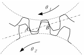
The normal view of the spiral bevel gear at the midpoint of the tooth width, where A and B are the theoretical meshing points. When the gear pair rotates without load, the gear teeth do not undergo elastic deformation, and the length of the meshing line does not increase. At this time, the transmission ratio is the theoretical transmission ratio. When the gear is loaded, the gear teeth undergo deformation due to loading, resulting in the phenomenon of entering the meshing ahead of time and exiting the meshing later. The actual meshing area is longer than the theoretical meshing area, so it is called out-of-line meshing or extended meshing.
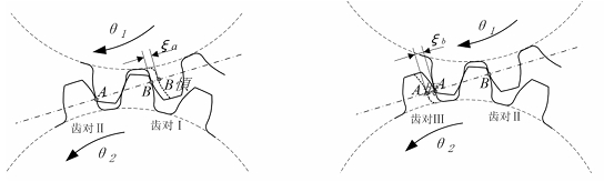
The load-bearing deformation of the gear causes a pair of gear teeth to enter and exit the meshing ahead of schedule, and the actual meshing interval is extended compared to the theoretical meshing interval. Due to the elastic deformation of tooth pair II, tooth pair I enters the meshing ahead of the theoretical meshing point, and tooth pair III exits the meshing after the theoretical meshing point. The advance meshing and delay meshing increase the actual overlap of the gear pair, and as the transmitted load increases, the overlap increases. The distance between a pair of gear teeth that are about to enter or just exit the meshing without elastic deformation is defined as the meshing interval.
Dynamics of Spiral Bevel Gear Pair
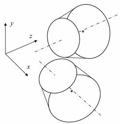
A concentrated parameter method is used to establish a torsional vibration model of an eight-degree-of-freedom spiral bevel gear. The intersection point of the two axes is taken as the origin of coordinates, with the pinion shaft as the X axis and the gear shaft as the Z axis. Torsional vibration and friction on the tooth surface are not included. There are eight degrees of freedom in the entire system, including lateral vibration along the XYZ axes axial vibration and torsional vibration.
Calculation example of spiral bevel gear
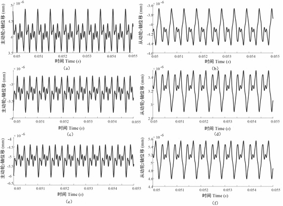
Take U(0) as the initial calculation value, where the displacement term is determined by the initial position of the system and is set to 0. The speed of the driving wheel is 5000 r/min, and the load of the driven wheel is 300N·m. Using the MATLAB software ode(45) function to solve, the time-varying displacement, velocity, and normal dynamic transmission error, dynamic meshing force of the gear in the coordinate direction can be obtained. The vibration impact is greater at the beginning and end of the meshing cycle. Through , it can be seen that the axial vibration displacement in the z direction is the largest The vibration displacement and vibration velocity on the driving and driven wheels maintain a high degree of consistency in their changing trends.
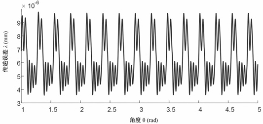
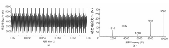
Further analysis of the dynamic meshing force of the spiral bevel gear pair. The dynamic meshing force of the spiral bevel gear pair at a speed of 5000r/min was simulated in both the time domain and frequency domain. In the time domain, the dynamic meshing force of the spiral bevel gear pair showed periodic fluctuations, and there was no separation of gear teeth, indicating a stable transmission quality. In the frequency domain, the main amplitude of the dynamic meshing force was at the meshing frequency (1916Hz) and multiple frequencies, with the maximum amplitude occurring at 5 times the meshing frequency. The Kv curve of the spiral bevel gear pair rapidly increased with the increase of discrete speed, then fluctuated, forming multiple distinct peak-valley structures.
When the load on the driven wheel is 300N·m, the speed of the driving wheel increases uniformly from 0r/min to 5000r/min within 0.5s; the angular velocity of the driving wheel. As can be seen from Figure 9, the average angular velocity of the driving wheel increases linearly, indicating that this model can be applied to the variable speed process of spiral bevel gear transmission. By taking U(0) as the initial calculation value, where the displacement term is determined by the initial position of the system and is set to 0, the dynamic meshing force of the system is simulated and calculated.
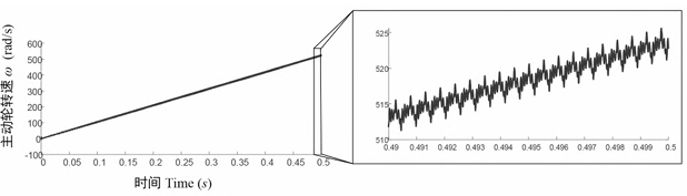
Under uniform acceleration transient conditions, compared to steady-state conditions, the amplitude of dynamic meshing forces during the meshing process of spiral bevel gear pairs fluctuates significantly, but no disengagement occurs.
conclusion
The dynamic model of the variable-speed transmission of the spiral bevel gear pair, which takes into account the off-line meshing, is used to analyze the dynamic response of the system under different steady-state and transient conditions. Under steady-state conditions, the vibration displacement and dynamic meshing force of the spiral bevel gear pair exhibit periodic fluctuations, especially at the beginning and end of the meshing cycle. In the frequency domain, the main frequency components of the dynamic meshing force are at the meshing frequency and its multiples, with the maximum amplitude occurring at five times the meshing frequency. Under transient conditions of variable speed, the speed of the system’s driving wheel increases uniformly, verifying the feasibility of the model in studying variable speed conditions; the system’s variable speed causes larger amplitude and dynamic meshing force fluctuations.