
This article presents a comprehensive analysis of the dynamic characteristics of a variable tooth thickness rotating vector (RV) reducer. This type of reducer represents an evolution from the conventional cycloidal RV reducer, offering high performance and precision crucial for applications in robotics, aerospace, and precision instrumentation. The primary mechanism for achieving theoretically zero-backlash operation is the axial adjustment of the beveloid gear via disc springs. Understanding the dynamic behavior of this complex transmission system is essential for performance optimization.
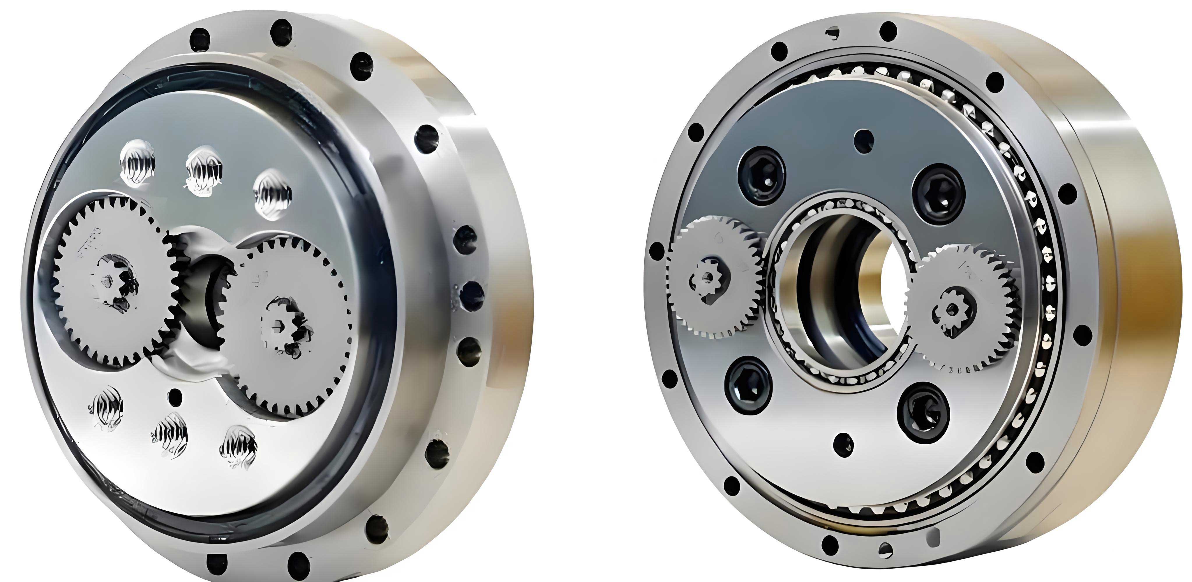
Transmission Principle and Structure
The variable tooth thickness RV reducer operates through a coupled two-stage transmission. The first stage is a standard involute planetary gear train. The second stage is a novel small tooth difference transmission utilizing a pair of beveloid (variable tooth thickness) gears. The power flow is as follows: An input shaft, integral with the sun gear, drives multiple planetary gears. These planetary gears are each connected to a crankshaft. The rotation of the crankshafts drives the beveloid external gear, which meshes with a fixed beveloid internal ring gear. Due to the tooth difference, the beveloid external gear undergoes a compound motion of revolution and rotation. When the internal ring gear is fixed, this motion is converted into a reduced output rotation at the carrier (planet carrier), which is the output member. A distinctive feature is the use of disc springs that apply an axial preload to the beveloid external gear, compensating for wear and manufacturing errors to minimize operational backlash in the RV reducer. The total speed ratio is given by:
$$
i = 1 + \frac{z_2}{z_1} \cdot \frac{z_5}{(z_5 – z_4)}
$$
where \( z_1 \) and \( z_2 \) are the tooth numbers of the sun and planet gears (first stage), and \( z_4 \) and \( z_5 \) are the tooth numbers of the beveloid external and internal gears (second stage), respectively.
Development of the System Dynamic Model
To accurately capture the dynamic behavior of the entire variable tooth thickness RV reducer, a coupled bending-torsion-axial vibration model is developed using a lumped-parameter approach based on Lagrangian mechanics. The model integrates both transmission stages, considering their mutual interactions.
Modeling Assumptions and Degrees of Freedom
The model includes the major load-bearing components: sun gear, multiple planetary gears, carrier, multiple crankshafts, and the beveloid gear pair. Non-load-carrying parts like screws and seals are neglected. The following degrees of freedom (DOFs) are considered for each component to account for spatial vibrations:
- Sun Gear: Two lateral translations (\(x_s, y_s\)), and torsional rotation (\(u_s\)).
- Planetary Gears: Two lateral translations (\(x_{pi}, y_{pi}\)), and torsional rotation (\(u_{pi}\)) for each planet i.
- Carrier: Two lateral translations (\(x_c, y_c\)), axial translation (\(z_c\)), and torsional rotation (\(u_c\)).
- Crankshafts: Two lateral translations (\(x_{shj}, y_{shj}\)), axial translation (\(z_{shj}\)), and torsional rotation (\(u_{shj}\)) for each crankshaft j.
- Beveloid External Gear: Two lateral translations (\(x_{gk}, y_{gk}\)), axial translation (\(z_{gk}\)), and torsional rotation (\(u_{gk}\)) for each external gear k (in a multi-gear design). The axial DOF is coupled with the disc spring stiffness.
The coordinate systems are established at the geometric center of each component.
System Energies and Equation Formulation
The system’s kinetic energy (\(T\)), potential energy (\(U\)), and dissipative energy (\(R\)) are formulated considering the masses, moments of inertia, and displacements of all components. The potential energy includes contributions from:
- Gear Meshing Stiffnesses: Time-varying mesh stiffness for the involute planetary stage (\(k_{msp}(t)\)) and for the beveloid gear stage. The beveloid mesh is characterized by both a tangential component (\(k_{mtrg}\)) and an axial component (\(k_{mzrg}\)), related by the pitch cone angle \(\gamma\): \(k_{mzrg} = k_{mtrg} \tan \gamma\).
- Bearing Support Stiffnesses: Radial and axial stiffness values for all supporting bearings, such as those between the crankshafts and the carrier (\(k_{xcshi}, k_{ycshi}, k_{zcshi}\)), and between the beveloid gear and crankshafts (\(k_{xgjshi}, k_{ygjshi}\)).
- Disc Spring Stiffness: Represented as an axial stiffness (\(k_{dh}\)) acting on the beveloid external gear.
The dissipative energy accounts for corresponding damping coefficients for meshing (\(c_m\)) and bearing supports (\(c_b\)). Applying the Lagrangian equation:
$$
\frac{d}{dt}\left( \frac{\partial L}{\partial \dot{q}} \right) – \frac{\partial L}{\partial q} + \frac{\partial R}{\partial \dot{q}} = F(t)
$$
where \(L = T – U\) is the Lagrangian, \(q\) is the generalized coordinate vector, and \(F(t)\) is the external force vector, yields the system’s equations of motion. These can be compactly expressed in matrix form:
$$
\mathbf{M}\ddot{\mathbf{q}} + [\mathbf{C}_b + \mathbf{C}_r + \mathbf{C}_m(t)]\dot{\mathbf{q}} + [\mathbf{K}_b + \mathbf{K}_{dh} + \mathbf{K}_r + \mathbf{K}_m(t)](\mathbf{q} + \mathbf{e}(t)) = \mathbf{F}(t)
$$
where \(\mathbf{M}\) is the mass matrix; \(\mathbf{K}_b, \mathbf{C}_b\) are bearing support stiffness and damping matrices; \(\mathbf{K}_{dh}\) is the disc spring stiffness matrix; \(\mathbf{K}_r, \mathbf{C}_r\) are the ring gear support matrices; \(\mathbf{K}_m(t), \mathbf{C}_m(t)\) are time-varying gear mesh stiffness and damping matrices; and \(\mathbf{e}(t)\) is the static transmission error excitation vector.
Dynamic Response Analysis of a Prototype RV Reducer
The developed model is employed to analyze the dynamic characteristics of a prototype variable tooth thickness RV reducer. Key parameters are listed in the table below.
| Parameter | Crankshaft | Sun Gear | Planet Gear | Beveloid Int. Gear | Beveloid Ext. Gear | Carrier |
|---|---|---|---|---|---|---|
| Mass \(m\) (kg) | 0.11 | 0.015 | 0.06 | 2.715 | 0.537 | 2.043 |
| Moment of Inertia \(I\) (kg·mm²) | 0.84E-2 | 1.24E-3 | 1.01E-2 | 5.052 | 1.159 | 10.19 |
| Number of Teeth \(Z\) | – | 18 | 36 | 78 | 80 | – |
| Module \(m_n\) (mm) | – | 1.25 | 1.25 | 1.5 | 1.5 | – |
| Pressure/Pitch Cone Angle | – | 20° | 20° | 47.6° / 2.5° | 47.6° / 2.5° | – |
Stiffness values were calculated as follows: bearing stiffnesses were derived from standard formulas; planetary mesh stiffness \(k_{msp}(t)\) was obtained analytically; beveloid gear mesh stiffness \(k_{mtrg}(t)\) was determined via finite element analysis and curve fitting; disc spring stiffness \(k_{dh}\) was treated as constant for small deflections.
Dynamic Meshing Forces
Under an input speed of 3000 rpm and a rated output torque of 412 N·m, the dynamic meshing forces were solved. The results show periodic fluctuations corresponding to the respective mesh frequencies.
Planetary Stage: The mean meshing force \(F_{sp}\) was 147.8 N, closely matching the theoretical static value (error ~1.96%). The dominant fluctuation frequency was 889 Hz, equal to the first-stage mesh frequency \(f_{msp}\).
Beveloid Stage: The mean meshing force \(F_{rg}\) was 3561.4 N, also aligning well with theory (error ~1.12%). Its fluctuation frequency was 1877 Hz, matching the second-stage mesh frequency \(f_{mrg}\). This confirms that the dynamic model of the RV reducer accurately captures the fundamental forced response.
Vibration Acceleration Response
The vibration acceleration responses of key components, such as the fixed beveloid internal ring gear and the output carrier, were analyzed in time and frequency domains.
The ring gear, being rigidly fixed, exhibited lower acceleration amplitudes compared to the carrier. The carrier showed significant radial vibrations, with axial vibrations being smaller due to stiffer axial constraints. Frequency spectrum analysis revealed that the ring gear’s vibration energy is predominantly excited by the second-stage beveloid meshing frequencies (\(f_{mrg}\) and its harmonics). In contrast, the carrier’s spectrum contains prominent frequency components from both the first-stage planetary meshing (\(f_{msp}\)) and the second-stage beveloid meshing. This clearly demonstrates the coupling effect between the two stages in the RV reducer. Ignoring the dynamics of the first stage would lead to an incomplete understanding of the system’s output behavior.
Transmission Error Analysis
Transmission error (TE), a critical metric for precision RV reducers, was investigated under varying operational conditions. TE is defined as the difference between the actual and theoretical output position of the carrier.
1. Influence of Load Torque
The load was varied from near-zero (0.1 N·m) to the rated torque (412 N·m). The results are summarized below.
| Load Torque \(T\) (N·m) | TE Peak-to-Peak (arcmin) | TE Mean Value (arcmin) |
|---|---|---|
| 0.1 | 0.093 | 0.007 |
| 100 | 0.102 | 1.345 |
| 200 | 0.112 | 2.691 |
| 300 | 0.123 | 4.036 |
| 412 | 0.134 | 5.512 |
Both the mean value and the peak-to-peak amplitude of the transmission error increase significantly with load. The increase in the mean TE is primarily due to the elastic deformation (contact, bending, torsion) of gear teeth, crankshafts, and bearings under load. The increased fluctuation is related to the heightened dynamic forces.
2. Influence of Disc Spring Initial Compression
The disc spring preload, defined by its initial compression \(\delta\), is a key design parameter for backlash control in this RV reducer. Its effect on TE was studied under rated load.
| Initial Compression \(\delta\) (mm) | TE Peak-to-Peak (arcmin) | TE Mean Value (arcmin) |
|---|---|---|
| 0.1 | 0.180 | 5.566 |
| 0.5 | 0.236 | 5.596 |
| 1.0 | 0.353 | 5.676 |
| 1.5 | 0.489 | 5.726 |
| 2.0 | 0.526 | 5.747 |
The initial compression has a pronounced effect on the dynamic component (peak-to-peak) of the transmission error. A larger preload introduces a stronger axial coupling stiffness, which can alter the system’s natural frequencies and potentially exacerbate vibrations under certain conditions, leading to larger TE fluctuations. The mean TE is less affected. This highlights a critical design trade-off for the RV reducer: sufficient preload is needed to eliminate backlash, but excessive preload can degrade dynamic precision.
3. Influence of Input Speed
The input speed was varied from 500 to 2500 rpm under rated load.
| Input Speed \(\omega\) (rpm) | TE Peak-to-Peak (arcmin) | TE Mean Value (arcmin) |
|---|---|---|
| 500 | 0.108 | 5.544 |
| 1000 | 0.112 | 5.543 |
| 1500 | 0.130 | 5.544 |
| 2000 | 0.127 | 5.545 |
| 2500 | 0.158 | 5.544 |
The input speed has a modest and non-monotonic influence on the peak-to-peak transmission error, likely due to the system passing through different resonance regions. The mean value of the TE remains virtually unchanged, as it is predominantly determined by the load-dependent elastic deflections rather than inertial effects.
Conclusion
This analysis provides a foundational framework for understanding the dynamics of the variable tooth thickness RV reducer. A coupled bending-torsion-axial dynamic model was successfully established, integrating both transmission stages and key elements like time-varying mesh stiffness, bearing supports, and the critical disc spring mechanism. The analysis of a prototype reveals that the dynamic characteristics of the first planetary stage significantly influence the output vibration, necessitating a coupled system analysis. Furthermore, the transmission error is strongly affected by the load and the disc spring preload setting, while the input speed has a secondary effect. The disc spring preload presents a clear design optimization challenge: minimizing backlash without inducing excessive dynamic transmission error. These findings offer essential theoretical guidance for the design, parameter selection, and dynamic performance optimization of high-precision variable tooth thickness RV reducers.