
The successful production of critical power transmission components is often a defining challenge in heavy machinery manufacturing. From my experience, few projects better illustrate this than the fabrication of the double herringbone gear shafts for large multi-point, multi-link mechanical presses. These shafts are not merely components; they are the very heart of the drive system, where precision directly translates to the synchronous operation of the press’s cranks and, ultimately, the quality of the stamped product. The requirement for extreme accuracy in the relative phase alignment between the two distinct sets of herringbone gears on a single shaft presents a formidable technical hurdle, compounded by the need for excellent surface finish on the gear teeth and a reliable method to verify the achieved precision. This account details the comprehensive process developed to overcome these challenges, ensuring the final components met the stringent design specifications.
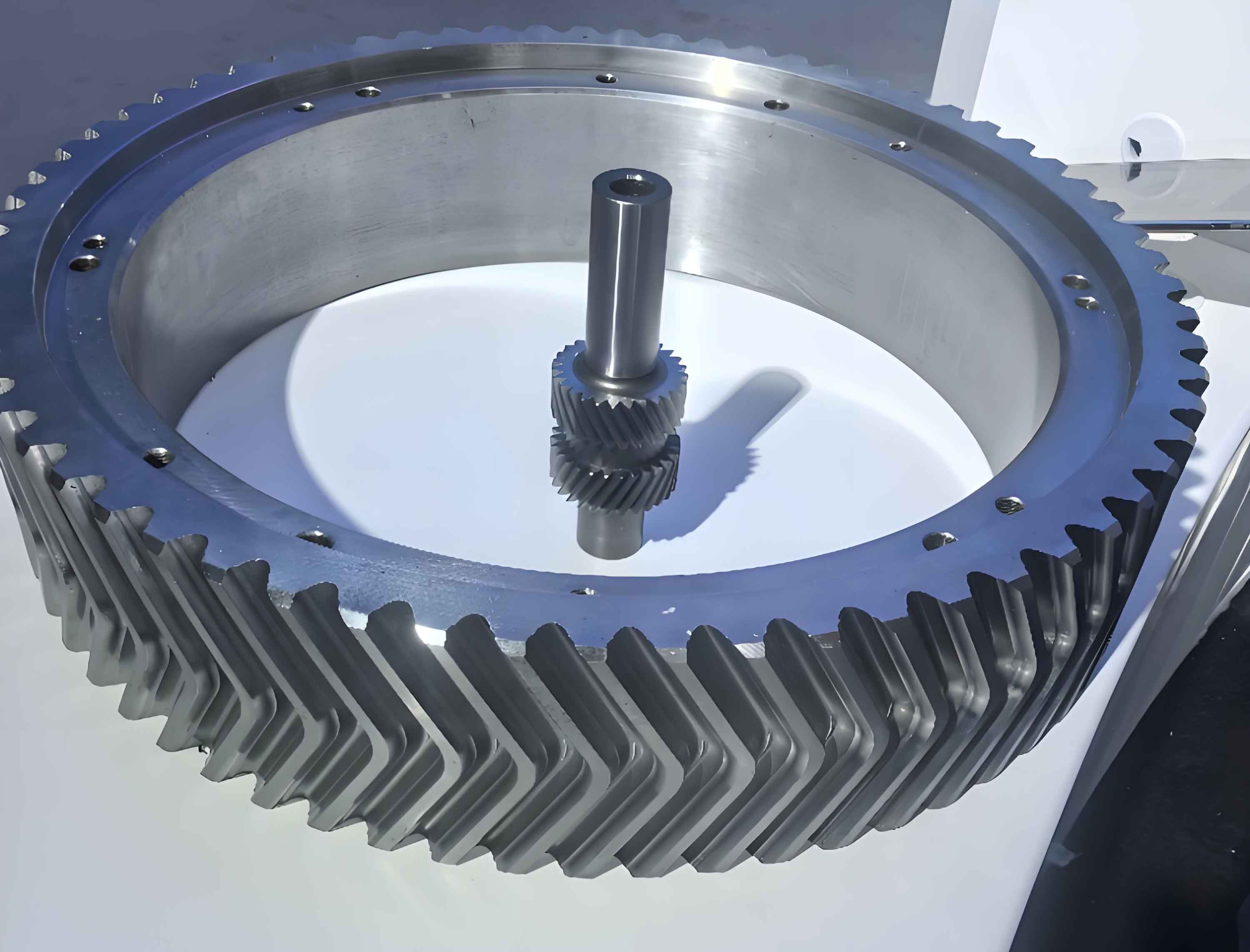
The unique design of herringbone gears, essentially two mirrored helical gears side-by-side, offers significant advantages in high-torque applications by canceling out axial thrust forces. However, when two such gear sets are required on a single shaft with a strict phase relationship, the manufacturing complexity increases exponentially. The primary technical obstacles identified were threefold. First, and most critical, was guaranteeing the phase synchronization between the front and rear herringbone gears. Any deviation here would introduce timing errors in the crank movement, leading to uneven press loading and potential part misalignment. Second, achieving a superior surface finish on the complex tooth flanks of the herringbone gears was essential for smooth meshing, reduced noise, and enhanced fatigue life. Third, devising a practical and accurate post-machining inspection method to quantify the phase difference was necessary to provide actionable data for assembly and system tuning, moving beyond subjective assessment.
The specifications for the double herringbone gear shaft demanded tolerances that pushed conventional machining approaches to their limits. A summary of the key precision requirements is presented below:
| Parameter | Specification | Criticality |
|---|---|---|
| Phase Alignment (Between Gear Sets) | < 0.10 mm (at measurement radius) | Ultra-Critical |
| Tooth Flank Surface Roughness (Ra) | ≤ 1.6 μm | High |
| Gear Tooth Profile Accuracy | AGMA 12 or better | High |
| Journal Runout | < 0.02 mm | High |
The manufacturing sequence was meticulously planned, with each stage building upon the precision of the last. The initial steps involved conventional turning to establish the primary shaft geometry, including the critical undercut relief grooves for the herringbone gear machining operations. Key journals were then ground to serve as reliable datums for subsequent processes. The first major challenge arose in machining the initial set of herringbone gears. A custom-designed, split-type locating sleeve was fabricated. This tooling was mounted in the tailstock of a gear planer. The shaft was supported at its center within this sleeve, which was then clamped shut, ensuring the rotational axis was maintained and concentricity was preserved relative to the pre-machined datums. This setup allowed for the accurate planing of the first full set of left and right-hand helical teeth that constitute one herringbone gear.
The machining of the second herringbone gear set on the opposite end of the shaft was the most delicate operation, pivotal for achieving the required phase lock. A horizontal hobbing machine was employed, but fitted with a single-point finger milling cutter instead of a hob. The setup and alignment procedure was a multi-step, iterative process of extreme care:
- Initial Alignment: The shaft was mounted between centers, referencing the ground journals. The index and differential change gears were set according to the gear’s helical lead and tooth count.
- Reference Establishment: The finger cutter was used to lightly touch off a tooth face on the already-planed first gear set. The cutter was then removed. The machine’s milling head spindle was brought close to the gear end-face, and the distance from the spindle centerline to the reference end was calculated based on spindle diameter $$D_{spindle}$$ and gear width $$B$$, yielding offset $$L = \frac{B}{2} + \frac{D_{spindle}}{2} + \delta_{clearance}$$, where $$\delta_{clearance}$$ was measured with a feeler gauge.
- Machine Zeroing: The milling head was positioned at the center of the relief groove (the axial center of the gear to be cut), and the digital readout was zeroed.
- Angular Registration: A dial indicator was set to zero against the same reference tooth face used in step 2.
- Translocation: The differential gear train was disengaged. The milling head was then traversed along the bed to the axial center of the second gear location, a distance precisely known from the part print.
- Phase Locking: The key step: the differential gears were re-engaged while ensuring the dial indicator reading against the reference tooth face did not change. This action effectively “carried” the exact angular orientation of the first gear set to the location of the second.
- Machining: The finger cutter was reinstalled and the roughing of the second set of herringbone gears commenced from the established center.
While effective for roughing, the finger milling process alone could not achieve the desired surface finish. For the finishing pass, the process shifted to a high-precision gear shaper. A dedicated fixture was designed to hold the shaft, allowing access to both gear sets. The shaper cutter, generating the exact tooth form, was used to take a final, light cut. The procedure was precise: one set of helices (e.g., left-hand) was finished, then the cutter head was swiveled to the opposite helix angle to finish the mirrored right-hand teeth, all while carefully maintaining the tooth thickness and, crucially, the phase by taking equal stock from both flanks. The shaft was then rotated 180 degrees in the fixture to identically finish the second herringbone gear set.
Following gear finishing, secondary operations like turning, final grinding of bearing journals, and spline hobbing were completed. The final, and equally critical, phase was metrology. A custom phase-checking gauge was manufactured. This gauge featured two precision ground pins mounted on a common base, spaced to span multiple teeth. The inspection protocol was as follows:
- The gear shaft was placed on V-blocks on a surface plate, and its axis was leveled using a height gauge.
- The checking gauge was clamped onto the first herringbone gear set, ensuring positive contact with the tooth flanks.
- The height of both pins was measured using a digital height gauge, and the values were averaged to establish a master height $$H_1$$ relative to the shaft axis.
- The gauge was then transferred and identically clamped onto the second herringbone gear set.
- The pin heights were measured again to establish average height $$H_2$$.
The phase error $$\Delta \phi$$, expressed as a linear deviation at the gauge pin radius $$R_{gauge}$$, is directly proportional to the height difference:
$$\Delta \phi \approx (H_2 – H_1)$$
This provides a direct, quantitative measure of the torsional misalignment between the two gear sets.
The entire manufacturing and inspection process is summarized in the following flowchart table:
| Process Stage | Key Operation | Precision Objective | Tooling/ Method |
|---|---|---|---|
| 1. Primary Machining | Turning & Grinding | Establish Datum Geometries | Lathe, Cylindrical Grinder |
| 2. First Gear Set Machining | Gear Planing | Form First Herringbone Profile | Planer with Custom Split Sleeve |
| 3. Second Gear Set Roughing | Finger Milling | Establish Phase-Locked Rough Gear | Horizontal Hobber with Precision Alignment Protocol |
| 4. Gear Finishing | Gear Shaping | Achieve Final Profile & Surface Finish (Ra ≤ 1.6 μm) | Precision Gear Shaper with Dedicated Fixture |
| 5. Final Operations | Grinding, Hobbing | Complete Shaft Features | Standard Machine Tools |
| 6. Metrology | Phase Difference Inspection | Quantify Phase Alignment (Target < 0.10 mm) | Custom Gauge & Surface Plate Measurement |
The efficacy of this integrated manufacturing strategy was validated by the inspection results. The measured phase error on the first completed double herringbone gear shaft was 0.08 mm, and on the second, an even more impressive 0.04 mm, both well within the specified tolerance. Furthermore, the tooth flank surface roughness consistently measured below Ra 1.6 μm. This successful outcome underscores that machining complex components like double herringbone gear shafts requires more than just capable machine tools. It demands a holistic approach where innovative process design, purpose-built tooling, meticulous alignment procedures, and rigorous final verification are all interlinked. The process not only solved the immediate production challenge but also established a reliable framework for manufacturing other high-precision, phase-critical gear systems, proving that with careful planning and execution, the formidable tolerances required by modern heavy machinery are indeed attainable.