There are several calculation methods for gear drive errors, including finite element method and empirical analysis method.The transmission error obtained by finite element method should be the most accurate but time-consuming and difficult to apply.Analytical method is the most commonly used method. It uses ISO method or Ishikawa formula to calculate the stiffness of individual teeth, and then synthesizes the meshing stiffness of gear pairs according to the overlap coefficient, which makes it difficult to fully consider the situation of modification and tooth profile errors.The foil theory is used to calculate the transmission error considering the actual tooth profile.
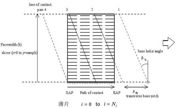
Figure 1 shows the contact area of a pair of helical gears with a coincidence between 2 and 3.There are 4 contact lines in the diagram, which means that the gear meshing transmission error with a maximum overlap of 4 can be calculated.Note that the actual end overlap does not exceed 2 because the end pitch is not less than half the length of the contact line.

“Flake” theory firstly divides the gear studied into equal parts with wN per unit length in the direction of tooth direction and lN per unit length in the direction of tooth height. Each unit represents a small increment in the rotation angle of the gear, so each tooth surface can be represented by W lN x N array.Each slice divided can be considered as a spring with a certain stiffness, and the sum of the forces on each spring is the total load applied on the tooth surface.
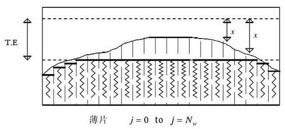
In the direction of the engagement line, for the angular position of each gear and each contact line, it is assumed that each slice is made of a spring, and under the action of load, part of the spring is compressed to form a transmission error, as shown in Figure 2.

