Helical gear systems often operate in complex environments such as high speeds, high temperatures, and harsh loads. In enclosed gearboxes, tooth breakage is one of the most common faults in helical gear transmission, which is difficult to detect. The occurrence of tooth breakage in helical gears can seriously affect the reliable operation and safety of mechanical transmission systems, reduce the fatigue life of helical gears, affect the performance and use of equipment, and even cause serious mechanical accidents. The time-varying mesh stiffness of helical gear pairs is an important parameter for dynamic analysis of helical gear systems, which can better reflect the vibration characteristics of helical gear systems under tooth breakage faults. Therefore, studying the dynamic characteristics of helical gears under tooth breakage faults is one of the important means to ensure equipment safety.
The time-varying mesh stiffness is often used as an input condition for the dynamic analysis of helical gear transmission systems, and scholars at home and abroad have conducted a series of studies on the time-varying mesh stiffness. Lin Tengjiao et al. conducted research on helical gears and analyzed the influence of various crack parameters on their meshing using finite element method. The results showed that the meshing stiffness of helical gears decreased with the increase of cracks; Ma Rui et al. established a theoretical model for a single pair of helical gears, analyzed their crack formation factors and vibration characteristics, and obtained the dynamic characteristics of helical gears containing cracks; Julia et al. proposed a method for calculating the meshing stiffness of helical gears based on the slicing idea and slicing coupling theory, and analyzed the time-varying meshing stiffness of helical gears; Wan Guozhi et al. proposed a mesh stiffness correction method that considers the non coincidence of tooth root circle and base circle, and used the potential energy method to solve the time-varying mesh stiffness of helical gears; Saxena et al. used the potential energy method to obtain the meshing stiffness of spur gear pairs and studied the influence of different crack lengths on the modal frequency response characteristics of helical gear rotor systems; Liu Wen et al. proposed a time-varying meshing stiffness correction algorithm for helical gears based on the slicing method and integration idea, when the size of the gear base circle and the tooth root circle are not consistent; Wang et al. proposed that the time-varying mesh stiffness of helical gears should also consider the axial bending stiffness, axial torsional stiffness, and axial matrix stiffness of helical gears; Xiao Zhengming analyzed planetary gears with cracks, established a dynamic model of the system, and conducted simulation analysis. The results showed that the established model had high accuracy. Wang Yangang et al. analyzed the nonlinear characteristics of helical gears under different faults, established a dynamic model of the helical gear system, and conducted analysis, which can effectively distinguish the size of fault signals. In terms of helical gear tooth breakage fault, Qiang Shijie et al. solved the meshing stiffness of helical gear pairs at any tooth breakage angle based on ISO stiffness calculation criteria; Yan Zuotang et al. extracted the fault characteristics of broken teeth and determined the severity and quantity of broken teeth through the analysis of broken tooth signals; Chen Baoqing et al. analyzed that the amplitude of meshing force increases significantly with the degree of tooth breakage.
Existing research has provided a good evaluation of the time-varying mesh stiffness of helical gears, but if fault factors can be comprehensively considered in a closed gearbox to study the dynamic response of the system’s vibration, it will be more helpful for studying the vibration characteristics of helical gear transmission systems. Therefore, this article establishes a three-dimensional model of helical gear tooth breakage to study the time-varying meshing stiffness law of helical gear pairs under tooth breakage faults. Based on the Runge Kutta method, the influence of different dynamic parameters on the dynamic characteristics of the transmission system under tooth breakage faults is analyzed, which has important engineering research significance for predicting the meshing state of helical gear pairs.
1. Modeling and meshing stiffness calculation of helical gears under tooth breakage fault
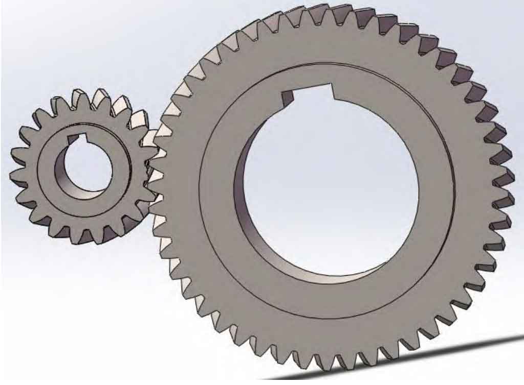
Considering that one of the teeth on the small gear has fractured, parameterized modeling using SolidWorks software is shown in Figure 1.
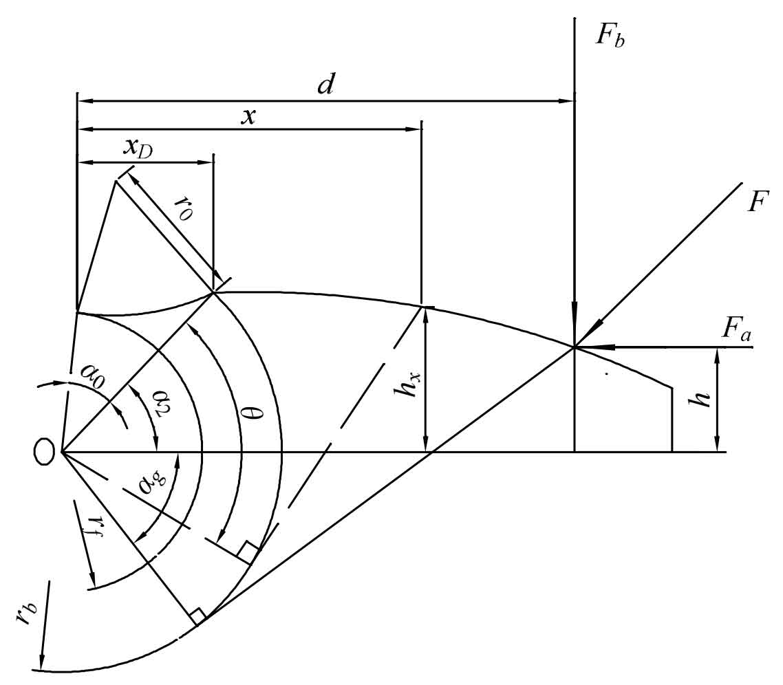
The accurate and effective method for calculating time-varying mesh stiffness is the key to conducting dynamic analysis, and the key to considering the calculation of time-varying mesh stiffness is to calculate the elastic deformation during gear tooth meshing. As shown in Figure 2, this article is based on the case of rb>rf, considering the fracture of one of the teeth of the small gear. The tooth meshing is equivalent to a variable cross-section beam, and the effective comprehensive meshing stiffness of the gear is obtained using the potential energy method. Figure 2: xD is the distance between the tooth root circle and the base circle in the direction of tooth height; The distance between the point on the tooth curve with x as the cross-section and the base circle in the direction of tooth height; D is the distance between the meshing point and the base circle in the tooth height direction; R0 is the radius of the circular arc on the tooth surface in contact with the base circle and the tooth root circle; The distance between the point on the tooth curve of the section hx and the centerline of the gear; H is the distance between the contact point and the centerline of the helical gear; α 0 is the angle between the tooth root circle and the base circle on the tooth surface; α 2 is the pressure angle; α G is the angle between the tangent of the meshing point in the tooth root direction and the centerline of the helical gear; θ The angle between the tangent point on the tooth curve of the cross-section in the direction of the tooth root and the tooth root circle; Fa is the shear force of the mating teeth at the meshing point; Fb is the bending force of the mating teeth at the meshing point; F is the combined force of the mating teeth in the meshing point.
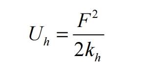
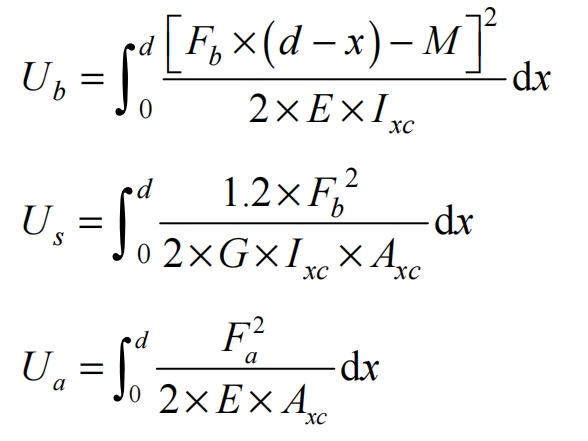
According to the elastic potential energy method, the Hertz contact energy, bending potential energy, shear potential energy, and axial compression energy during the meshing process of helical gears are considered to calculate the comprehensive meshing stiffness of tooth breakage faults. According to the energy method, the stored potential energy of the meshing helical gear is:
According to the relationship between potential energy and stiffness, it can be concluded that:
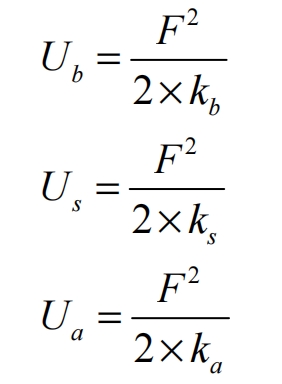
In the formula: Uh is the Hertz stiffness; Ub is the bending potential energy; Us is the shear energy; Ua is the axial compression energy; Kh is the Hertz stiffness; Kb is the bending stiffness; Ks is the shear stiffness; Ka is the axial stiffness; Ixc is the effective area moment of inertia; Axc is the effective cross-sectional area,; The bending effect of torque M as Fb.
The Hertz contact stiffness of the helical gear is obtained as:
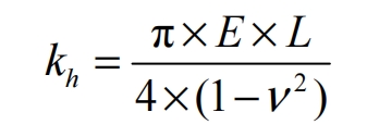
In the formula: E is the Young’s modulus; L is the length of the contact wire; V is the Poisson’s ratio.
The bending stiffness of helical gears is shown in the formula, the shear stiffness is shown in the formula, and the compression stiffness is shown in the formula.
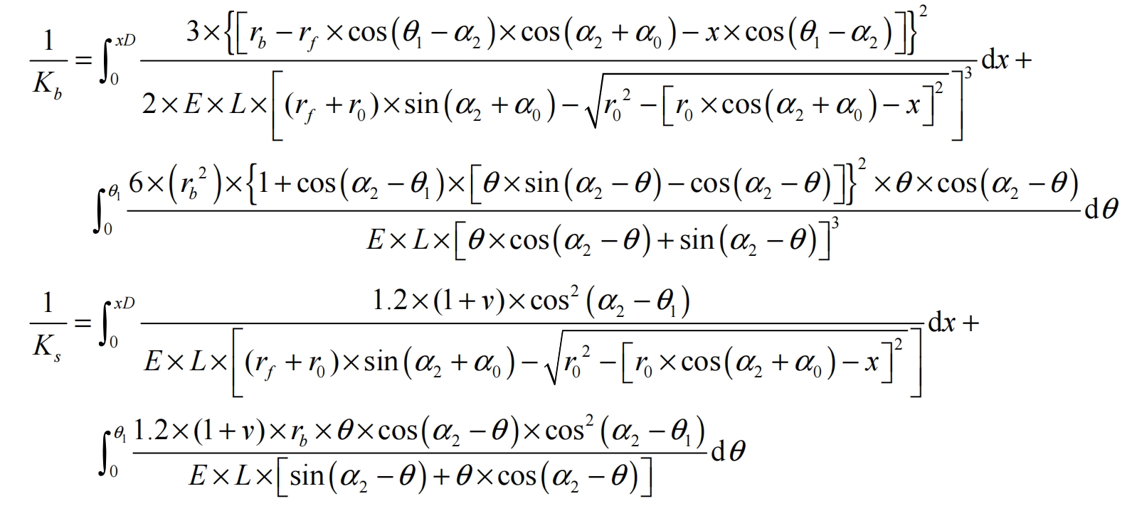

In the formula: θ 1 is the angle between the tangent point of the meshing point in the direction of the tooth root and the tooth root circle.
According to the formula, the comprehensive meshing stiffness is:

In the formula, subscripts 1 and 2 represent small gears and large gears, respectively.
As shown in Figure 1, one of the teeth on the small gear has broken. If the tooth is not broken, when it rotates to the meshing area, it will mesh with the large gear that matches the helical gear. In the double tooth meshing area, the fractured teeth did not make contact and remained in single tooth meshing. Therefore, the comprehensive effective meshing stiffness is equivalent to the single tooth meshing stiffness, and the comprehensive effective meshing stiffness is:

The parameters for using helical gears are shown in Table 1.
| Parameter Name | Parameter values |
| Number of teeth | Z1/Z2=19/48 |
| Young’s modulus E/Pa | 2.06×10^11 |
| Poisson’s ratio v | 0.3 |
| Normal modulus m/mm | 3.175 |
| Normal pressure angle α2 | 20° |
| Gear pair center a/mm | 106.3625 |
| Tooth width B/mm | 16 |
| Small gear root circle radius rf/mm | 27.12 |
| Small gear base circle radius rb/mm | 29.11 |
| Moment of inertia/(kg · mm ^ 2) | Ip=184, Ig=7500 |
| Graduation circle helix angle β/ Rad | 0.2443 |
| Equivalent mass Me/kg | 0.188 |
| Meshing damping coefficient ζ | 0.10 |
| Bearing damping coefficient ζ | 0.05 |
| Radial displacement coefficient Cx | 0.25 |
2. The effect of tooth breakage on the time-varying mesh stiffness of helical gears
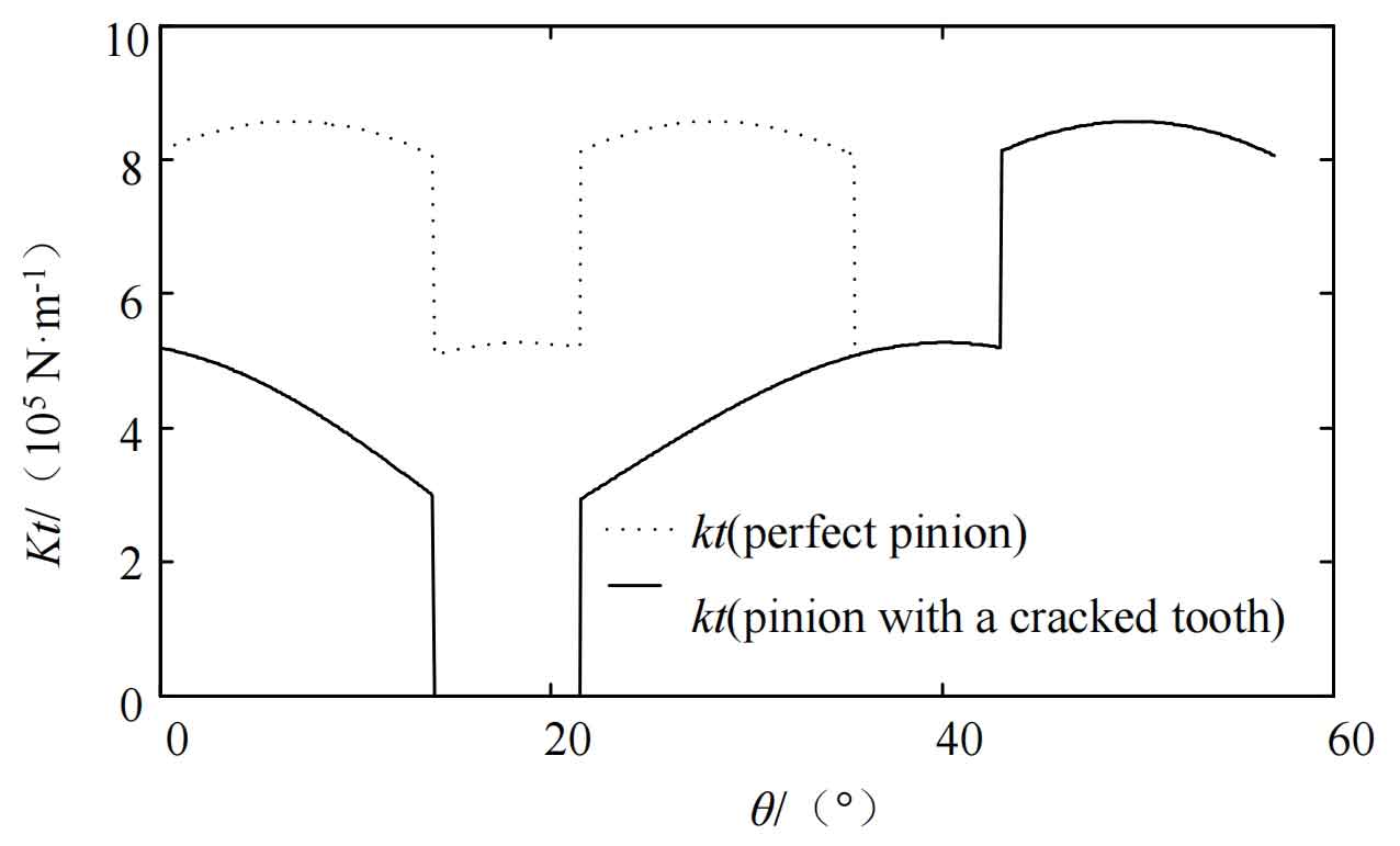
Assuming that the small gear is a faulty gear with broken teeth, a single tooth meshing occurs in the double tooth meshing area, and its comprehensive meshing stiffness is shown in Figure 3. It can be concluded that the meshing stiffness of the faulty teeth in a pair of helical gears participating in meshing is significantly reduced compared to an ideal helical gear.
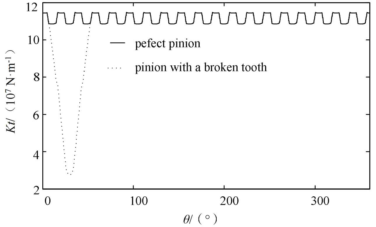
The use of slice method to study the periodic time-varying meshing stiffness of helical gears for periodic continuous transmission is meaningful in revealing the operating rules of helical gears. Figure 4 shows the time-varying mesh stiffness variation of helical gears under ideal and broken tooth faults. By comparison, it can be seen that the comprehensive meshing stiffness of the helical gear pair under tooth breakage fault is lower than the corresponding ideal comprehensive meshing stiffness of the helical gear pair in the fault contact area. The comprehensive meshing stiffness in the meshing area of the broken tooth fault is significantly reduced, but due to the cross meshing of helical gears, the comprehensive meshing stiffness of the broken tooth fault will not be zero.
3. Dynamic model of torsional vibration of helical gears
A single degree of freedom dynamic model of a helical gear pair was established using the concentrated mass method, taking a single stage tooth breakage fault helical gear transmission system as the research object. The model includes time-varying meshing stiffness, time-varying meshing damping, static transmission error, and frictional excitation. The model is shown in Figure 5.
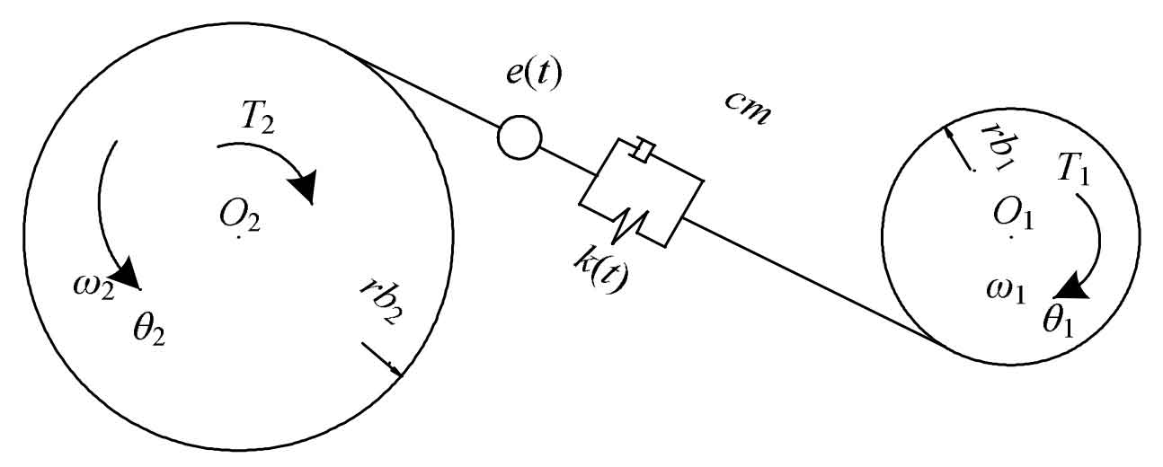
In the formula, Ip and Ig represent the moment of inertia of the small gear and the large gear, respectively; Tp and Tg respectively apply constant torque to the small gear and the large gear; M1 and M2 represent the time-varying friction torque on the small gear and the large gear, respectively; θ P θ G represents the rotation angles of the small gear and the large gear, respectively; β Is the helix angle of the dividing circle; Rb1 and rb2 are the base radius of the small gear and the large gear, respectively; K (t) is the time-varying mesh stiffness; Cm is the meshing damping; E (t) is the comprehensive error of the gear teeth.
Based on the transmission system parameters and models provided in this article, the 2012 version of Fortran simulation software was used to solve the vibration response of the helical gear transmission system with broken teeth using the variable order Runge Kutta method.
4. Analysis of torsional vibration dynamic characteristics of helical gears
4.1 Effect of rotational speed on the dynamic characteristics of torsional vibration of helical gears
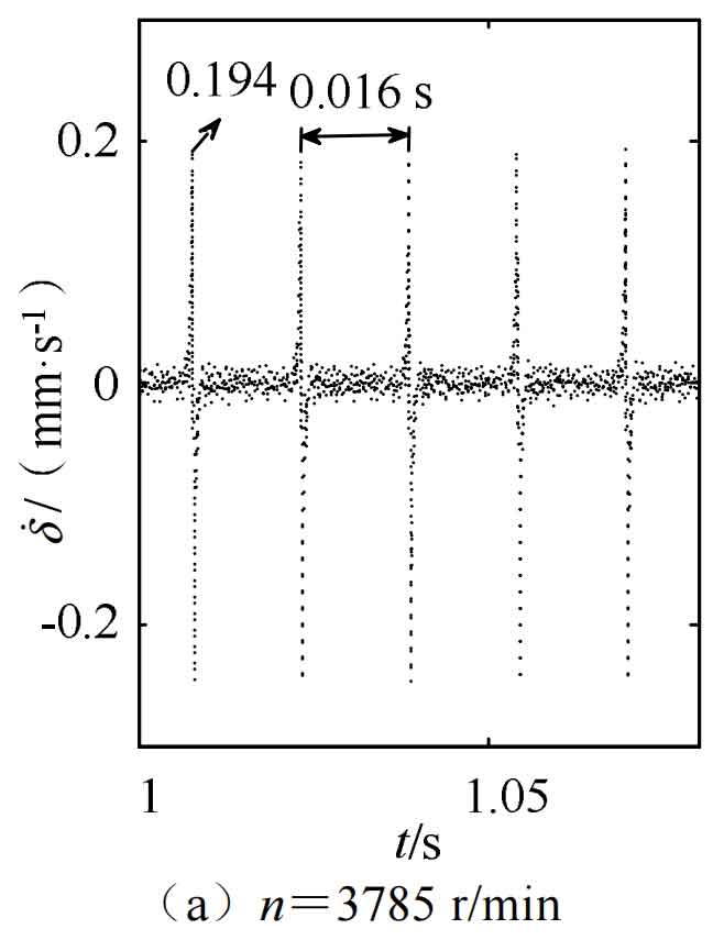
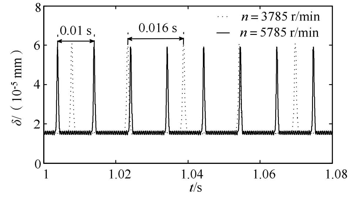
Figures 6-8 show the dynamic characteristics at a torque of 50000 N · m and speeds of 3785 r/min and 5785 r/min, respectively.
The dynamic equation for torsional vibration can be obtained from Newton’s second law as follows:

As shown in Figure 6, the dynamic transmission error of teeth with broken teeth at different speeds exhibits periodic impact response intervals and strong vibration responses, with values of 0.016 s and 0.01 s, respectively. The impact interval at lower speeds is 1.6 times that at higher speeds.
As shown in Figure 7, the teeth of the helical gear with broken teeth have periodic impact response intervals and strong vibration response at different speeds, with maximum values of 0.194 mm/s and 0.2604 mm/s respectively. When the speed is high, the vibration speed is relatively stable and intense. As shown in Figure 8, the vibration acceleration of the teeth with helical gear tooth breakage fault exhibits periodic impact response intervals and strong vibration response at different speeds, with maximum values of 4009 mm/s2 and 5017 mm/s2, respectively. When the speed is high, the vibration acceleration is relatively stable and intense.
4.2 The influence of torque on the dynamic characteristics of torsional vibration of helical gears
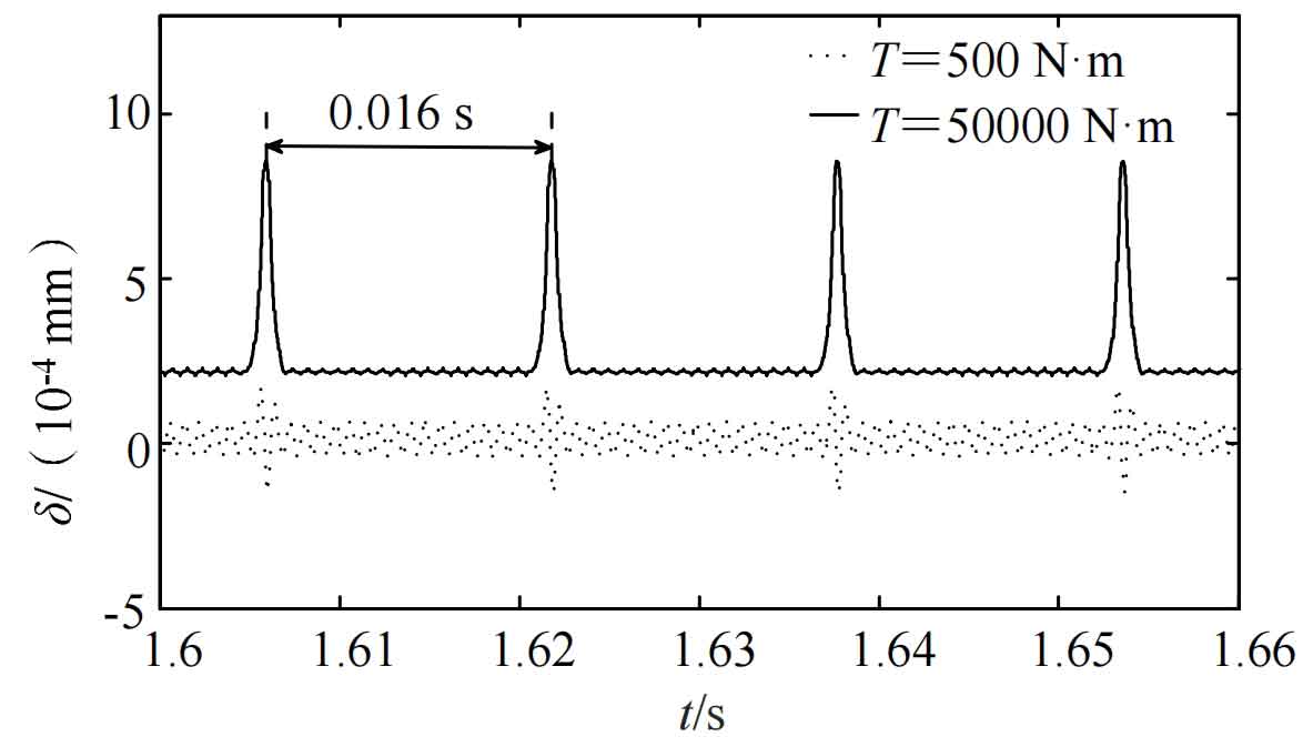
Figures 9-11 show the dynamic characteristics at speeds of 3785 r/min and torques of 500 N · m and 50000 N · m, respectively. It can be seen that small gears with broken teeth exhibit obvious periodicity and strong vibration response under different torque conditions.
As shown in Figure 9, the dynamic transmission error with a torque of 50000 N · m is higher than that with a torque of 500 N · m. As shown in Figure 10, the vibration speeds are 1.406 mm/s and 2.735 mm/s, respectively. When the torque is high, the vibration speed response is more stable and intense. As shown in Figure 11, the maximum vibration accelerations are 6716 mm/s2 and 56500 mm/s2, respectively. When the torque is high, the vibration acceleration vibration response becomes smoother and stronger.
4.3 The influence of tooth breakage fault on the torsional vibration dynamic characteristics of helical gears
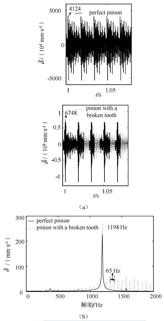
At a speed of 3785 r/min, the tooth rotation frequency is 63 Hz and the meshing frequency is 1198 Hz. Figures 12-14 show the dynamic time-domain response changes and corresponding frequency-domain changes under the condition of helical gear tooth breakage fault under no fault conditions, with a torque of 500 N · m and a speed of 3785 r/min.
As shown in Figure 12 (a), there is a periodic impact response interval in the time domain response of dynamic transmission error under the fault of helical gear tooth breakage, which is higher than the time domain response under no fault. As shown in Figure 13 (a), there is a periodic impact response interval in the time-domain response of vibration velocity under the fault of helical gear tooth breakage, which is higher than the time-domain response under no fault. As shown in Figure 14 (a), the time-domain response of vibration acceleration under helical gear tooth breakage fault has a periodic impact response interval, with a maximum of 6748 mm/s2. The time-domain response without tooth breakage fault is 4124 mm/s2, and the time-domain response under helical gear tooth breakage fault is higher than that without fault.
As shown in Figures 12 (b), 13 (b), and 14 (b), the frequency domain response spectra corresponding to the dynamic transmission error, vibration velocity, and vibration acceleration under no fault conditions and under the condition of helical gear tooth breakage fault at a torque of 500 N · m and a speed of 3785 r/min exhibit frequency modulation sidebands centered on the meshing frequency. The dynamic transmission error, vibration velocity, and There is a significant frequency conversion vibration effect in the frequency domain response spectrum of vibration acceleration. The edge frequency effect and vibration amplitude frequency of the gear teeth under the fault of helical gear tooth breakage are higher than those under the fault of no tooth breakage. In the dynamic transmission error response spectrum, the frequency interval between adjacent edge frequency effects is 64 Hz, and the meshing frequency is 1198 Hz. In the vibration velocity response spectrum, the frequency interval between adjacent edge frequency effects is 63 Hz, and the meshing frequency is 1198 Hz. The frequency interval between adjacent edge frequency effects in the vibration acceleration response spectrum is 65 Hz, and the meshing frequency is 1198 Hz. The presence of helical gear tooth breakage fault leads to inconsistent rotation frequency of the edge frequency effect. The edge frequency effect in the vibration acceleration response spectrum is higher than the dynamic transmission error and vibration velocity edge frequency effect. The rotation frequency and meshing frequency of the gear teeth correspond to the rotation frequency and meshing frequency of the helical gear with broken teeth. The dynamic characteristics under this change can be used to analyze the existence of tooth breakage faults in the transmission system.
5. Conclusion
Using the established three-dimensional model and dynamic model under tooth breakage fault, summarize the time-varying mesh stiffness changes and dynamic characteristics of a pair of single stage transmission system helical gear breakage fault factors, and draw the following conclusions:
(1) The presence of tooth breakage faults in helical gears affects the time-varying stiffness of the meshing of the teeth, which in turn affects the dynamic response of the system.
(2) The failure of helical gears with broken teeth has a significant impact on the meshing stiffness of the gear pair. For gears with broken tooth areas, the overall meshing stiffness will be significantly reduced.
(3) A dynamic model of the transmission system with helical gear tooth breakage fault was established. Through dynamic simulation, it was found that when there is helical gear tooth breakage, the system’s dynamic transmission error occurs, and there is a periodic impact response phenomenon in vibration speed and acceleration. The higher the rotational speed, the faster the system’s dynamic transmission error vibration response, and the larger the vibration speed and acceleration, the more stable and strong the vibration response. The dynamic transmission error of high torque is higher than that of low torque. The larger the vibration speed and acceleration, the smoother and stronger the vibration response.

