
In the realm of precision transmission systems for robotics and aerospace, the rotary vector reducer stands out due to its compact design, high reduction ratio, exceptional accuracy, and rigidity. As a core component of this system, the cycloid-pin gear transmission profoundly influences the overall transmission precision, efficiency, and load-bearing capacity. To facilitate assembly, ensure lubrication, and compensate for inherent manufacturing inaccuracies, modification of the cycloidal gear tooth profile is not just beneficial but essential. Traditional modification methods, while theoretically sound, often fall short in practical engineering scenarios where combinations of part machining errors can lead to assembly interference or excessive backlash, posing significant challenges for batch production and selective assembly. Therefore, this article presents, from my perspective, a comprehensive investigation into a novel secondary conjugate modification method for the cycloidal tooth profile, fundamentally centered on real-time compensation for key machining errors. This methodology aims to bridge the gap between theoretical design and practical manufacturability, offering a robust framework for the design and assembly stages of the rotary vector reducer.
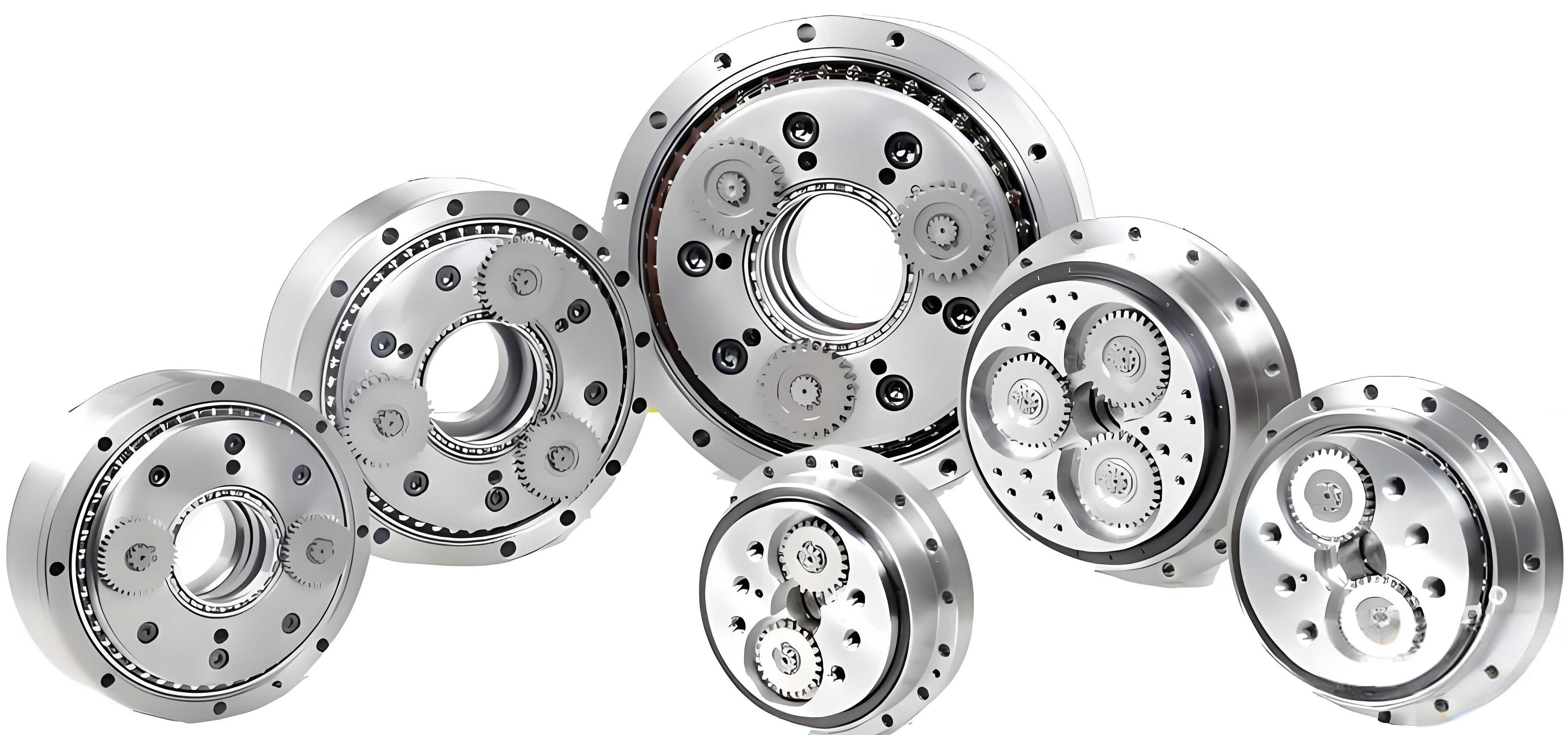
The transmission principle of a standard rotary vector reducer involves a two-stage process: a first-stage involute planetary gear train and a second-stage cycloid-pin wheel planetary gear train. The latter, comprising the cycloid gear, pins, pin housing, crankshaft, and planet carrier, is the primary contributor to the overall transmission error. My analysis, consistent with prior sensitivity studies, identifies several critical error sources whose compensation is paramount: the pin housing center circle radius error ($\delta r_p$), the pin radius error ($\delta r_{rp}$), and the circumferential position error of the pin holes ($\delta t$). While technologies exist to control errors in the cycloid gear itself (like pitch accumulation error), the aforementioned errors related to the pin wheel are often more challenging and costly to minimize during manufacturing. Consequently, my proposed method strategically targets these specific errors for compensation through tooth profile modification, thereby relaxing manufacturing tolerances and reducing cost.
Existing modification strategies predominantly employ combinations of equidistant modification ($\Delta r_{rp}$), radial movement modification ($\Delta r_{p}$), and rotational angle modification. While effective in creating backlash for assembly, these methods typically determine modification amounts during the design phase based on nominal dimensions, without explicit consideration for the stochastic nature of actual part errors. When multiple parts with varying error magnitudes are assembled, the theoretically modified profile may result in interference (if errors stack in one direction) or excessively large clearance (if errors stack in the opposite direction). This necessitates selective grouping of parts—a process that lacks a systematic theoretical basis under traditional methods. My proposed secondary conjugate modification method directly addresses this shortcoming by integrating an error compensation model into the modification process itself.
The core of my methodology is a two-phase process. The first phase involves primary modification for theoretical zero-backlash, where machining errors are actively compensated. The second phase involves secondary modification for practical conjugate action with controlled clearance, where an optimal profile is derived to ensure smooth meshing while meeting specified radial clearance and backlash (return error) constraints.
Phase One: Error Compensation Model and Primary Modification
I establish an error compensation model that equivalently translates part errors into corresponding amounts of equidistant or radial movement modification. The principle is to equate the circumferential backlash induced by an error on the cycloid gear’s distribution circle to the backlash created by a specific modification. The fundamental equations for circumferential backlash ($j$) caused by various factors are:
$$j_{\Delta} = \Delta r_{rp}$$
$$j_{rp} = \delta r_{rp}$$
$$j_s = \Delta r_p \sqrt{1 – k_1^2}$$
$$j_t = k_1 \delta t$$
$$j_p = \delta r_p \sqrt{1 – k_1^2}$$
where $k_1 = a z_p / (r_p + \Delta r’_p)$ is the curtate coefficient after the primary radial movement modification, $a$ is the eccentricity, $z_p$ is the number of pins, and $r_p$ is the nominal pin center circle radius. To compensate for an error, I set the backlash it causes equal to the backlash from a modification: $j_{rp} = j_{\Delta}$ for pin radius error, $j_t = j_{\Delta}$ for pin hole position error, and $j_p = j_s$ for pin housing radius error. This yields the primary compensation modification amounts for individual errors, as summarized in the table below.
| Error Source | Error Sign | Compensation Modification Type | Compensation Amount |
|---|---|---|---|
| Pin Radius Error $\delta r_{rp}$ | Positive (+) | Positive Equidistant | $\Delta r_{rp1} = |\delta r_{rp}|$ |
| Pin Radius Error $\delta r_{rp}$ | Negative (-) | Negative Equidistant | $\Delta r_{rp1} = -|\delta r_{rp}|$ |
| Pin Hole Pos. Error $\delta t$ | Positive (+) | Positive Equidistant | $\Delta r_{rp2} = |k_1 \delta t|$ |
| Pin Hole Pos. Error $\delta t$ | Negative (-) | Negative Equidistant | $\Delta r_{rp2} = -|k_1 \delta t|$ |
| Pin Hous. Rad. Error $\delta r_p$ | Positive (+) | Positive Radial Movement | $\Delta r_{p1} = |\delta r_p|$ |
| Pin Hous. Rad. Error $\delta r_p$ | Negative (-) | Negative Radial Movement | $\Delta r_{p1} = -|\delta r_p|$ |
In real-world assembly, errors coexist. Therefore, the total primary modification amounts are the algebraic sum of individual compensations:
$$\Delta r’_{rp} = \Delta r_{rp1} + \Delta r_{rp2}$$
$$\Delta r’_{p} = \Delta r_{p1}$$
Furthermore, under load, elastic deformation occurs at the contact between the cycloid gear and pins. To pre-compensate for this, I incorporate the elastic deformation function $\delta(\phi)$ into the profile equation. The deformation is approximated as:
$$\delta(\phi) = \frac{\sin \phi}{\sqrt{1 + k_1^2 – 2k_1 \cos \phi}} \delta_{max}$$
where $\phi$ is the angular position of the pin relative to the turning arm, and $\delta_{max}$ is the maximum elastic deformation of the most loaded tooth. Substituting the total primary modifications and the deformation into the standard equidistant-radial movement modified profile equation yields the primary modified profile for theoretical zero-backlash, denoted as $(x’_z, y’_z)$:
$$
\begin{aligned}
x’_z &= \left[ (r_p + \Delta r’_p) – (r_{rp} + \Delta r’_{rp} + \delta) s^{-\frac{1}{2}} \right] \cos\left[(1-i_H)\phi\right] – \frac{a}{r_p + \Delta r’_p} \left[ (r_p + \Delta r’_p) – z_p (r_{rp} + \Delta r’_{rp} + \delta) s^{-\frac{1}{2}} \right] \cos(i_H \phi) \\
y’_z &= \left[ (r_p + \Delta r’_p) – (r_{rp} + \Delta r’_{rp} + \delta) s^{-\frac{1}{2}} \right] \sin\left[(1-i_H)\phi\right] + \frac{a}{r_p + \Delta r’_p} \left[ (r_p + \Delta r’_p) – z_p (r_{rp} + \Delta r’_{rp} + \delta) s^{-\frac{1}{2}} \right] \sin(i_H \phi)
\end{aligned}
$$
where $i_H = z_p / z_c$ is the transmission ratio, $z_c$ is the number of cycloid gear teeth, and $s = 1 + k_1^2 – 2k_1 \cos \phi$.
Phase Two: Determination of Secondary Conjugate Modification
The primary profile, while theoretically perfect, is impractical as it provides no radial clearance at the tooth root and tip for assembly and lubrication. Therefore, a secondary modification is necessary to introduce controlled clearances while maintaining a conjugate (or near-conjugate) meshing condition in the working segment of the tooth profile. I propose to achieve this by applying an additional set of equidistant and radial movement modifications ($\Delta r^*_{rp}$, $\Delta r^*_{p}$) to create a final profile that optimally approximates the working segment of the primary profile.
The working segment on the primary profile is defined between two limit points B’ and C’, corresponding to pin angles $\phi_b$ and $\phi_c$, chosen to minimize the average pressure angle within the segment, thus optimizing force transmission. This segment is discretized into $m$ points along the X-axis, yielding a coordinate set $(x’_{zi}, y’_{zi})$ for $i=1,2,…,m$ from the primary profile equation. For a given trial secondary modification pair $(\Delta r^*_{rp}, \Delta r^*_{p})$, a corresponding point set $(x^*_{zi}, y^*_{zi})$ on the secondary profile can be calculated using the same profile equation but with the new total modifications: $\Delta r’_{rp} + \Delta r^*_{rp}$ and $\Delta r’_{p} + \Delta r^*_{p}$.
The objective is to minimize the deviation between these two profiles over the working segment. I define the objective function as the mean absolute deviation of their Y-coordinates:
$$f(\Delta r^*_{rp}, \Delta r^*_{p}) = \frac{1}{m} \sum_{i=1}^{m} | y^*_{zi} – y’_{zi} |$$
Minimizing $f$ ensures the secondary profile closely follows the conjugate meshing path of the primary profile in the working zone. However, practical constraints must be enforced. The introduction of secondary modification inherently creates circumferential backlash $j$ and radial clearance $\Delta r$. The backlash, which directly relates to the transmission return error $\gamma$, must be controlled for high precision. The equations are:
$$j = \Delta r^*_{rp} – \Delta r’_{rp} – \frac{\Delta r^*_{p} \sqrt{1 – k_2^2}}{1 + \frac{\Delta r’_{rp} \sqrt{1 – k_1^2}}{2}} \quad \text{(simplified form)}$$
$$\gamma(\Delta r^*_{rp}, \Delta r^*_{p}) = 2 \times \frac{j}{a z_c} \times \frac{180 \times 60}{\pi} \quad \text{(in arc-minutes)}$$
$$\Delta r = (\Delta r^*_{rp} + \Delta r’_{rp}) – (\Delta r^*_{p} + \Delta r’_{p})$$
where $k_2 = a z_p / (r_p + \Delta r^*_{p})$ is the curtate coefficient after secondary radial movement. For a high-precision rotary vector reducer, typical constraints are: return error $\gamma \leq 1’$, absolute secondary equidistant modification $|\Delta r^*_{rp}| \leq 0.20$ mm, and radial clearance $0 < \Delta r \leq 0.03$ mm.
Thus, I formulate the secondary modification determination as a constrained optimization problem:
$$
\begin{aligned}
& \underset{\Delta r^*_{rp}, \Delta r^*_{p}}{\text{minimize}}
& & f(\Delta r^*_{rp}, \Delta r^*_{p}) \\
& \text{subject to}
& & \gamma(\Delta r^*_{rp}, \Delta r^*_{p}) \leq 1′ \\
& & & |\Delta r^*_{rp}| \leq 0.20 \text{ mm} \\
& & & 0 < \Delta r \leq 0.03 \text{ mm}
\end{aligned}
$$
Solving this nonlinear optimization problem using iterative methods like the least squares approach yields the optimal secondary modification amounts $(\Delta r^*_{rp}, \Delta r^*_{p})$. The final, manufacturable cycloidal tooth profile is then obtained by applying the total modifications $(\Delta r’_{rp}+\Delta r^*_{rp}, \Delta r’_{p}+\Delta r^*_{p})$ to the standard profile equation, now without the elastic deformation term $\delta(\phi)$ as it is compensated in the primary phase.
Validation through Finite Element Analysis and Case Study
To validate the efficacy of my proposed error-compensated secondary conjugate modification method, I conducted a detailed case study using an RV-80E type rotary vector reducer as a benchmark. The key design parameters are listed below.
| Parameter | Symbol | Value |
|---|---|---|
| Pin Center Circle Radius | $r_p$ | 58 mm ($^{+0.02}_{-0.02}$ mm) |
| Pin Radius | $r_{rp}$ | 2.5 mm ($^{+0.004}_{-0.004}$ mm) |
| Eccentricity | $a$ | 1 mm ($^{+0.004}_{-0.004}$ mm) |
| Number of Pins | $z_p$ | 40 |
| Number of Cycloid Teeth | $z_c$ | 39 |
| Rated Torque | $T$ | 412 N·m |
I established a finite element analysis (FEA) model focusing on the second-stage cycloid-pin transmission. The model included the cycloid gear, crankshaft, pin housing, and pins with appropriate material properties (20CrMnMo for cycloid gear/crankshaft, GCr15 for pins/housing). Contact definitions with friction (coefficient 0.1) were applied between mating surfaces, and boundary conditions simulated the actual mounting. The mesh was refined around contact zones to ensure accuracy. Validation of the FEA model was performed by comparing the contact stress distribution under load with analytical Hertzian contact calculations, showing agreement within a 10% margin, confirming model reliability.
I designed an orthogonal experiment to test my method under various single and combined error conditions. Three error factors ($\delta r_{rp}$, $\delta r_p$, $\delta t$) were each set at three levels (negative tolerance, nominal zero, positive tolerance). Nine distinct error combination models (Models 1-9) were created according to an L9 orthogonal array, plus a nominal error-free model (Model 10) for baseline comparison. For each model, I calculated the required primary and secondary modifications using my proposed methodology. Crucially, in several error combinations (e.g., Models 1, 4, 5, 7), traditional theoretical modification would result in tooth profile interference, rendering assembly impossible. My method, however, successfully computed viable modification amounts for all models.
The performance of the profiles generated by my method was evaluated via FEA simulation for each model, quantifying the maximum contact stress on the cycloid gear and the transmission error (both peak-to-peak and maximum value). The results were compared against the performance of profiles generated by the traditional theoretical modification method (where applicable). The key outcomes are consolidated in the following summary table.
| Model | Error Combination | Max. Transmission Error [‘] | Transmission Error Peak-Peak [‘] | Max. Contact Stress [MPa] | Simultaneous Contact Teeth | |||
|---|---|---|---|---|---|---|---|---|
| Theoretical | Proposed | Theoretical | Proposed | Theoretical | Proposed | (Proposed) | ||
| 1 | $\delta r_{rp}^-$, $\delta r_p^-$, $\delta t^-$ | — (Interference) | 1.52 | — | 1.16 | — | 1054 | 8 |
| 2 | $\delta r_{rp}^-$, $\delta r_p^0$, $\delta t^0$ | 1.56 | 1.15 | 0.53 | 0.44 | 1102 | 1037 | 8 |
| 3 | $\delta r_{rp}^-$, $\delta r_p^+$, $\delta t^+$ | 2.02 | 1.52 | 0.90 | 0.60 | 1323 | 1139 | 7 |
| 4 | $\delta r_{rp}^0$, $\delta r_p^-$, $\delta t^0$ | — (Interference) | 1.35 | — | 0.42 | — | 1050 | 8 |
| 5 | $\delta r_{rp}^0$, $\delta r_p^0$, $\delta t^+$ | — (Interference) | 1.39 | — | 0.60 | — | 1113 | 7 |
| 6 | $\delta r_{rp}^0$, $\delta r_p^+$, $\delta t^-$ | 3.49 | 1.51 | 1.79 | 1.15 | 1303 | 1051 | 8 |
| 7 | $\delta r_{rp}^+$, $\delta r_p^-$, $\delta t^+$ | — (Interference) | 1.48 | — | 0.60 | — | 1040 | 7 |
| 8 | $\delta r_{rp}^+$, $\delta r_p^0$, $\delta t^-$ | 1.52 | 1.45 | 1.15 | 1.12 | 1150 | 1057 | 8 |
| 9 | $\delta r_{rp}^+$, $\delta r_p^+$, $\delta t^0$ | 2.54 | 1.35 | 0.71 | 0.42 | 1213 | 1128 | 7 |
| 10 | Nominal (No Error) | — | 1.35 | — | 0.42 | — | 1140 | 7 |
The results demonstrate the robust performance of my method. In all cases, including those where traditional methods fail, my approach generated viable tooth profiles. On average, compared to the traditional method where applicable, my method reduced the maximum transmission error by 32%, the transmission error peak-peak value by 26%, and the maximum contact stress by 11%. Furthermore, the number of teeth in simultaneous contact remained high (7 or 8), ensuring good load distribution. The transmission error and contact stress values for models with compensated errors closely approached or even bettered the nominal error-free baseline model, confirming effective error compensation. For instance, in Model 2, compensation for a negative pin radius error resulted in slightly better transmission accuracy than the nominal model, as the effectively larger cycloid gear generated a more favorable meshing condition.
Discussion and Engineering Implications
The proposed error-compensated secondary conjugate modification method offers a paradigm shift in the design and assembly philosophy for rotary vector reducers. Its primary advantage lies in its ability to systematically account for and neutralize the effects of key manufacturing errors through intelligent tooth profile design. This has several profound implications:
1. Relaxation of Manufacturing Tolerances: By providing a compensatory mechanism via modification, the stringent (and often costly) tolerances on components like the pin housing and pins can be relaxed. Manufacturers can produce these parts within broader, more economical tolerance bands without sacrificing final assembly performance.
2. Rationalization of Selective Assembly: In batch production, part dimensions vary. My method provides a theoretical foundation for selective assembly. The process can be systematized as follows: First, measure the actual errors ($\delta r_{rp}$, $\delta r_p$, $\delta t$) of the pin housing and pins after machining. Second, group these components based on their error magnitudes. Third, for each group combination, use my model to calculate the required cycloid gear modification amounts ($\Delta r^*_{rp}, \Delta r^*_{p}$) that will yield the desired performance (meeting constraints on $\gamma$ and $\Delta r$). Fourth, manufacture or select cycloid gears with modification amounts falling within the calculated ranges for each group. This transforms selective assembly from a trial-and-error process into a precise, model-driven operation.
3. Enhancement of Transmission Performance: Beyond mere error compensation, the secondary conjugate optimization phase ensures the meshing condition is optimized for the working segment. This leads to a more uniform distribution of contact stress across the teeth, reducing peak stresses and potentially increasing the fatigue life and overload capacity of the rotary vector reducer. The controlled minimization of the objective function $f$ ensures the kinematic accuracy of the transmission is preserved even after introducing necessary clearances.
4. Design Phase Flexibility: During the initial design of a rotary vector reducer, engineers can use this method to perform tolerance analysis and allocate tolerances optimally. By simulating various error stack-ups, they can determine the allowable part variation that still permits a viable modification solution, thereby optimizing the design for manufacturability and cost.
It is important to note that the method relies on accurate measurement of part errors. The compensation is only as good as the input error data. Furthermore, the optimization model assumes the elastic deformation function is accurately estimated; for significantly different materials or loading conditions, this function may need recalibration. Future work could explore integrating more complex deformation models or thermal effects into the compensation framework.
Conclusion
I have presented a comprehensive error-compensated secondary conjugate modification methodology for the cycloidal tooth profile in rotary vector reducers. This two-phase approach first actively compensates for critical machining errors (pin radius, pin housing radius, pin hole position) through equivalent primary modification amounts to achieve a theoretical zero-backlash condition, inclusive of pre-compensation for elastic contact deformation. Subsequently, a constrained optimization determines secondary modification amounts that introduce controlled radial and circumferential clearances while ensuring the final tooth profile closely follows a conjugate meshing path in the working zone.
Validation through finite element analysis on an RV-80E model under an orthogonal array of error combinations confirms the method’s robustness and superiority over traditional theoretical modification. It successfully prevents assembly interference in critical error combinations, reduces transmission error by approximately one-third, lowers maximum contact stress by over 10%, and maintains a high number of teeth in contact. The method effectively decouples the final transmission performance from the absolute precision of individual components, allowing for the use of parts with wider, more economical manufacturing tolerances.
This methodology possesses significant engineering application value. It serves as a powerful tool during the design phase for tolerance allocation and design-for-manufacture. More importantly, it provides a rigorous, model-based framework for implementing selective assembly in batch production of rotary vector reducers, moving beyond empirical guesswork. By reducing the dependency on ultra-high-precision machining for every component, this approach can contribute to lowering the overall cost while maintaining, or even enhancing, the performance and reliability of these critical precision transmission systems. The principles outlined here may also find application in the modification strategies of other types of precision gear transmissions where error compensation is a key concern.