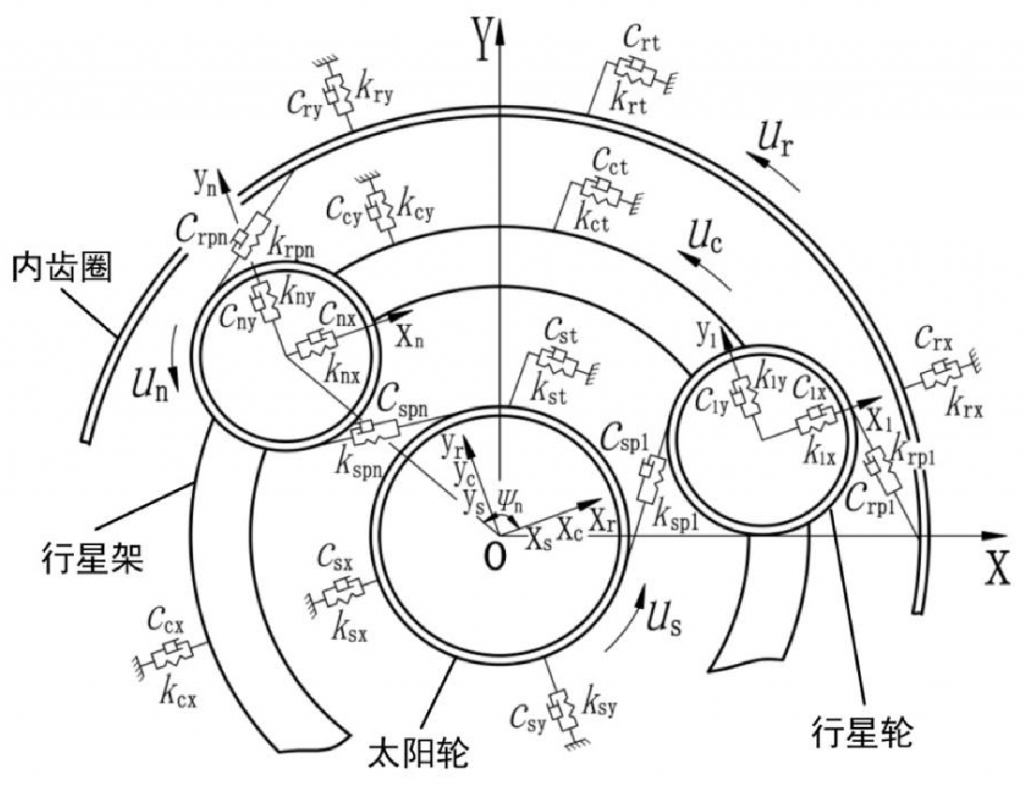
The model of gear transmission system is the expression of system mechanics and mathematics, and is the basis of gear dynamics analysis. A good model can accurately simulate the actual system, and can simplify the problem and reduce the amount of calculation to a certain extent. For the single-stage planetary gear transmission system studied in this chapter, the dynamic model of the system is established by using the lumped parameter method. The variables in the model have no relationship with the spatial position.
Each component contains three degrees of freedom, which are translation degrees of freedom in vertical and horizontal directions and rotational degrees of freedom about their own axis. Considering the complexity of the translational torsional dynamic model established in this paper, before analyzing its dynamic characteristics, it is necessary to make relevant reasonable simplification and assumptions on the structure of the system
(1) The mass of each component in the system is concentrated at one point of the mass center; the meshing motion between the teeth is simplified as the relative motion between two mass blocks connected by spring and damping in the direction of the meshing line; the radial and circumferential supports of the component are equivalent to the elastic spring and damping of tension and compression and torsion respectively, and the spring and damping are regarded as the elastic elements without mass.
(2) The gears studied in this paper are all involute standard spur gears, ignoring the axial force, all components vibrate in the plane perpendicular to the axis, ignoring the friction between the components;
(3) The quality and machining accuracy of each planetary gear are the same, which are evenly distributed on the planet carrier, and the support stiffness of each planetary gear is the same;
As shown in the figure is the translation torsion coupling dynamic model of the spur gear transmission system established in this paper. Considering that each component contains three degrees of freedom, and the relative motion relationship between the components is relatively complex, in order to facilitate the establishment of the dynamic model and the subsequent solution, the following system coordinate system is established, and the position on the diagram is defined as the initial reference position, and oxy is taken as the initial reference position As an absolute reference coordinate system, the origin o is located at the rotation center of the planetary carrier, and this coordinate system is fixed; oxryr, oxcyc and oxsys are the dynamic coordinate systems on the inner gear ring, planetary carrier and sun gear respectively, and the origin o is located at the rotation center of the planetary carrier, and the X of the three coordinate systems is X The axis passes through the theoretical center of the first planetary gear, and is fixedly connected with the planetary carrier, and rotates at the same speed with the planetary carrier at its theoretical speed; the coordinate system onxnyn is the coordinate system fixed with the planetary carrier and rotates with the planetary carrier at constant speed. The origin on is located at the theoretical center of the nth planetary gear, and the two coordinate axes are parallel to the two coordinate axes of the coordinate system oxcyc on the planetary carrier. The choice of coordinate system does not change the physical characteristics of planetary gear transmission system, only affects the degree of difficulty in the analysis process.

In the picture:
KIX, KiY — the radial support stiffness of the ith member (I = s, C, R, 1, 2, 3,…, n);
CiX, ciy — represents the radial support damping of the ith member;
KJT represents the stiffness of the jth member (J = s, C, R);
Cjt — represents the damping of slewing support of planetary gear;
CSPN — the meshing damping between the nth planetary gear and the sun gear;
Crpn — the meshing damping between the nth planetary gear and the inner ring gear;
UI — represents the torsional line displacement of the ith member; for planetary carrier, it is the radius of the distribution circle of the planetary gear center; θ I is the angular displacement of each component; in this paper, it is specified that the counter clockwise direction is positive.
