
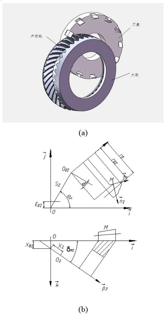
According to the geometric relationship of the hypoid gear and the requirements of gear processing, the processing parameters of the large hypoid gear wheel are calculated, and the processing model of the large hypoid gear wheel is established according to the processing parameters, as shown in Figure 1. Where (a) is the machining entity model of the large wheel, and (b) is the coordinate system of the large wheel machining.
Hypoid gear wheels are generally machined by double-sided method. In the machining process, the inner and outer cutters of the cutter head are involved in cutting, and the convex and concave surfaces of the wheels are machined respectively. The cutting cone formed by the internal and external cutting edges of the cutter head and the shaking table form an imaginary plane generating wheel. The machining process of the generating method big wheel can be regarded as the meshing movement between the generating wheel and the hypoid gear big wheel, that is, the generating gear tooth surface and the big gear tooth surface form a pair of conjugate surfaces, which can be obtained from the geometric relationship. According to the conjugate surface theory, the big gear tooth surface of the hypoid gear can be obtained from the meshing principle.
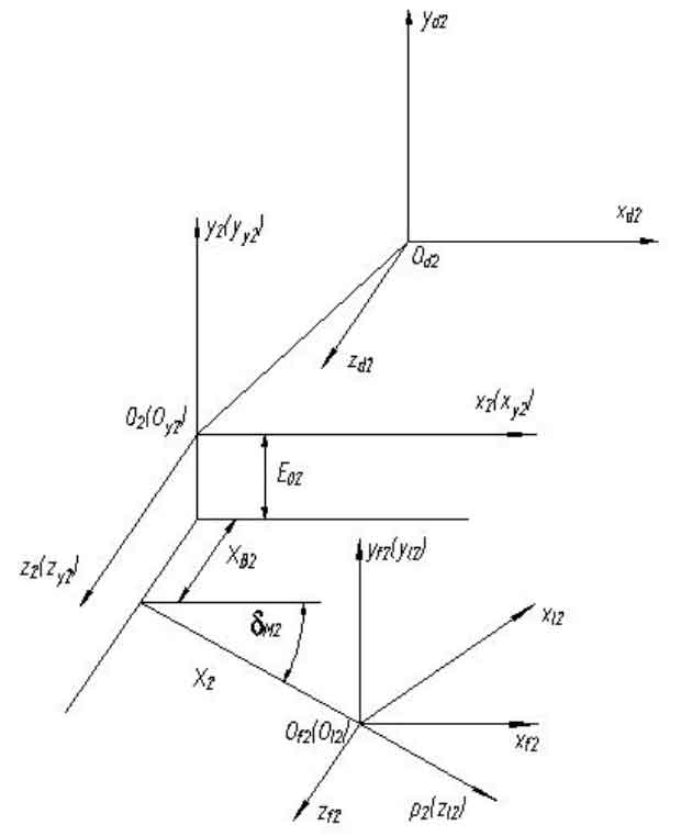
The coordinate system shown is the machine coordinate system. In the actual calculation process, it is necessary to complete the transformation from the cutter head coordinate system to the cradle coordinate system, the cradle coordinate system to the machine tool coordinate system, and the machine tool coordinate system to the wheel blank coordinate system. The specific transformation coordinate system is shown in Figure 2 below.
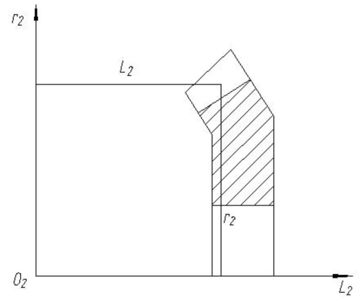
The tooth surface of spiral bevel gear is a curved surface formed by fitting discrete points. Generally, 5 x 9 tooth surface points are selected on the large tooth surface of hypoid gear. Generally, the selection principle is 5 rows in the direction of tooth height and 9 columns in the direction of tooth length. The number of points can also be increased or decreased according to actual needs. 5×9 tooth surface points are used, that is, 45 groups of (R2, L2) values. R2 and L2 are determined according to geometric calculation, as shown in Figure 3.