
When machining spiral bevel gears, the cutter head tip plane is tangent to the root cone rather than parallel to the gear pitch line, which has an error in principle. The machined large and small tooth surfaces cannot be completely consistent with each other. In order to avoid bad contact during meshing, the tooth surface must be corrected by using the local conjugate principle.
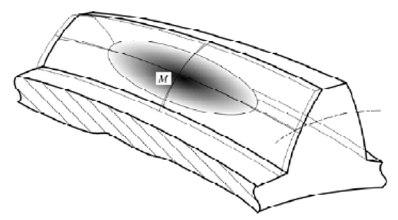
The principle of local conjugation means that the tooth surface of the small wheel which is completely conjugated with the machined gear tooth surface can be obtained through the gear meshing principle. However, this kind of tooth surface of the small wheel can not be machined and can only be modified. Select a point m on the tooth surface of the small wheel, and then scrape a layer of material around the point m. The farther away from the point m, the more material will be scraped. In theory, the contact between the tooth surface of the small wheel and the big wheel is point contact. Due to the elastic deformation of the material and other factors, the contact point is not a point but an area . The schematic diagram of local contact area is shown in Figure 1.
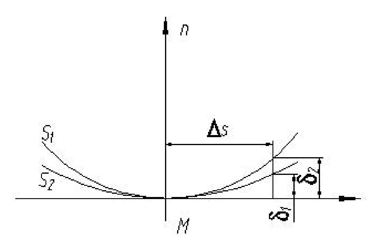
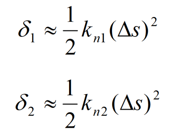
From the mathematical point of view, the local conjugate contact is actually the curvature correction of the pinion tooth surface. Its mathematical model is shown in Fig. 2. The surface S1 and S2 are at the distance m point Δ The distances from s to abscissa are:
Subtract the above two formulas to get:
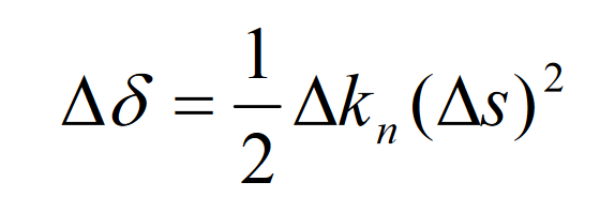
Of which Δ Kn=kn1-kn2, for spiral bevel gear, it is the induced curvature of conjugate tooth surface of large and small gear.
Based on a large number of experiments, Gleason company concluded that when the distance between the two tooth surfaces is less than 0.00635mm, the contact marks can be detected with red lead powder. The size of the contact area during the movement of two tooth surfaces is determined according to this principle.
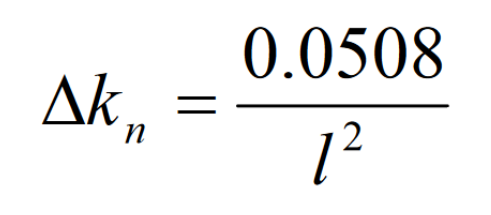
Set Δ Kn is the induced normal curvature of the two surfaces along a tangent direction at the contact point. It is required to obtain the relationship between the length of the contact area of the two surfaces along this tangent direction and the induced curvature. The contact length can be set as l when Δ When s = l/2, Δδ = 0.00635, finally:
The above formula only discusses the curvature correction in one direction. On spiral bevel gears, it is necessary to consider not only the curvature correction in the tooth length direction, but also the curvature correction in the tooth height direction and the short-range torsion correction in the tooth length direction.
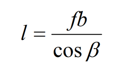
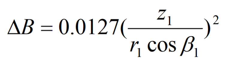
Let the tooth surface width be B and the helix angle be β, The tooth surface length is approximately b/cos β, Then the contact length is:
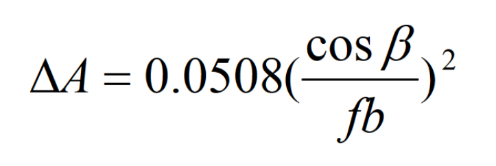
Where f is the ratio of the length of the contact area to the length of the tooth surface. By substituting the above formula into the formula, it can be obtained that the induced curvature correction value of the gear tooth surface in the tooth length direction is:
In actual production, the curvature correction of the tooth length direction is carried out in two parts, one part is corrected on the radius of the large wheel cutter head, and the other part is corrected on the radius of the small wheel cutter head. It is generally required that the tooth length curvature of the convex surface of the small wheel increases and the tooth length curvature of the concave surface of the small wheel decreases.
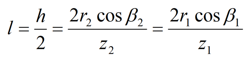
The curvature correction in the tooth height direction is carried out according to that the width of the contact area is half of the tooth height, namely:
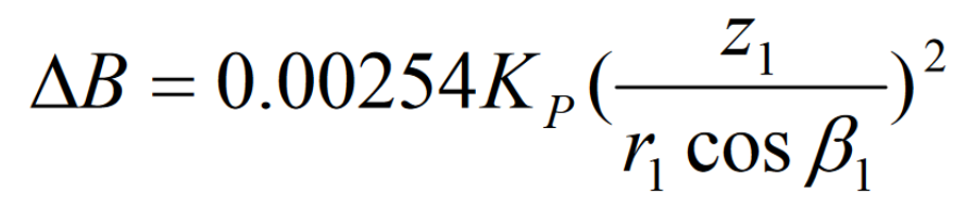
The normal curvature correction value in the tooth height direction can be obtained by substituting the formula into:
The tooth height curvature correction factor KP is introduced, and the above formula is rewritten as:
The correction of tooth height curvature is generally only carried out on the small wheel, and the contact area needs to be narrowed. KP is a little larger, otherwise it is a little smaller. In addition, it should be considered that the tooth height curvature is opposite to the symbol on the concave convex surface of the small wheel.
Two points should be paid attention to in the correction of short-range torsion along the tooth length direction: curvature interference and diagonal contact. Except for the calculation points, other points of the corrected tooth surface shall be lower than the theoretical tooth surface, and the farther the point is, the farther the distance from the theoretical tooth surface should be. The short-range torsion is mainly related to the direction of the contact track. The ideal contact track direction is perpendicular to the tooth length direction, otherwise it is diagonal contact. However, in most cases, the contact track is diagonal contact and needs to be adjusted according to the actual situation.