1. Modeling of gear tooth surface
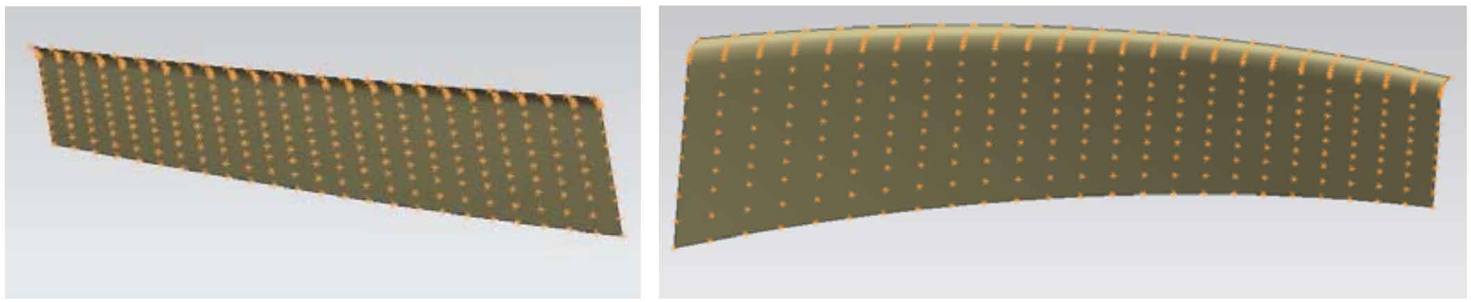
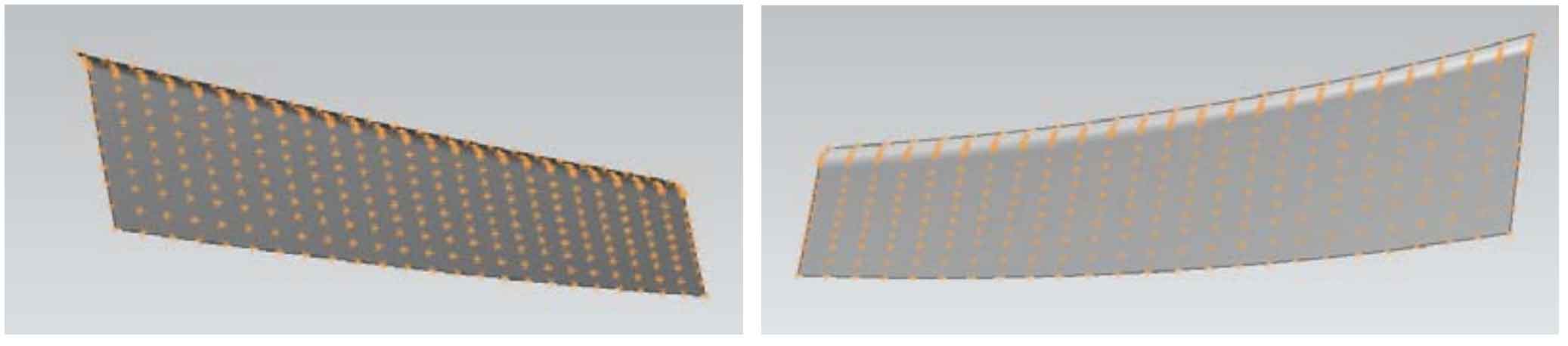
Importing the data of tooth surface points into UG can generate tooth surface pieces. The denser the tooth surface points, the higher the modeling accuracy of gear teeth. The tooth surface points are composed of 15 * 25 calculation points. Figure 1 shows the tooth surface of the convex surface of the large wheel of spiral bevel gear, and Figure 2 shows the tooth surface of the concave surface of the large wheel.
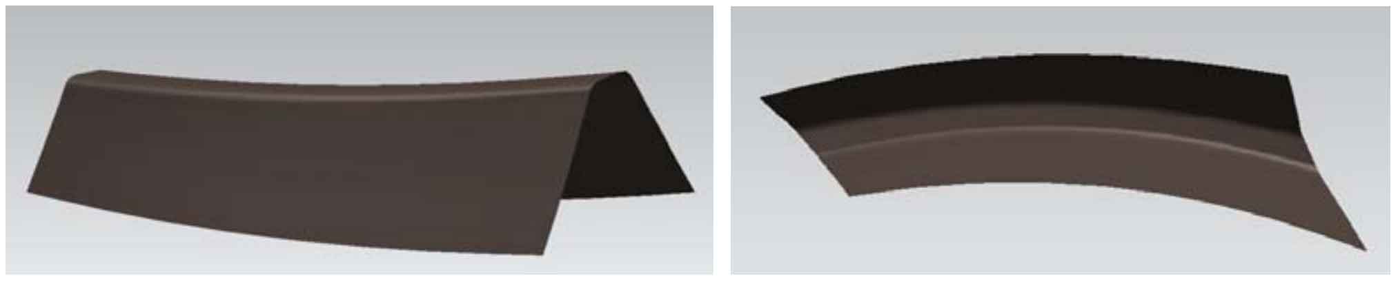
Use the “ruled surface” command in UG to connect the convex and concave tooth patches of the big wheel to generate the transition surface, then “extend” the boundary of the tooth patch, and then use the “stitch” command to sew each surface into a whole to generate the tooth patch of the big wheel teeth, as shown in Fig. 3; In this process, because the tooth top of the tooth surface piece corresponds to the tooth root of the spiral bevel gear, the generated ruled surface has little impact on the overall accuracy of the gear and will not reduce the modeling accuracy.
2. Establishment of wheel blank model
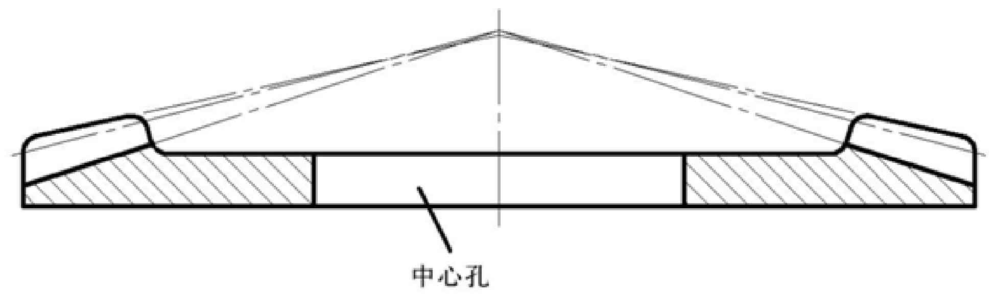
According to the basic parameters of cold precision forged spiral bevel gear calculated in Chapter 2, first draw the wheel blank of spiral bevel gear. Through the “sketch” command, first draw the pitch cone of spiral bevel gear from the pitch cone angle and outer cone distance parameters, and then draw the face cone and root cone through the pitch cone according to the parameters such as tooth top height, tooth root height, face cone angle and root cone angle, Cut the tooth width and length as the tooth surface of the wheel blank, design the back size of the spiral bevel gear, expand the center hole to the gear tooth according to Fig. 4, draw the sketch of the large wheel blank, as shown in Fig. 5, rotate the sketch of the wheel blank to generate the wheel blank model, as shown in Fig. 6.
3. Establishment of large and small wheel models
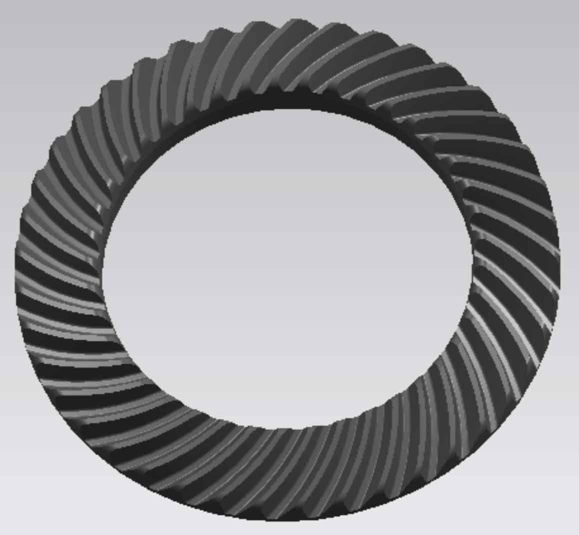
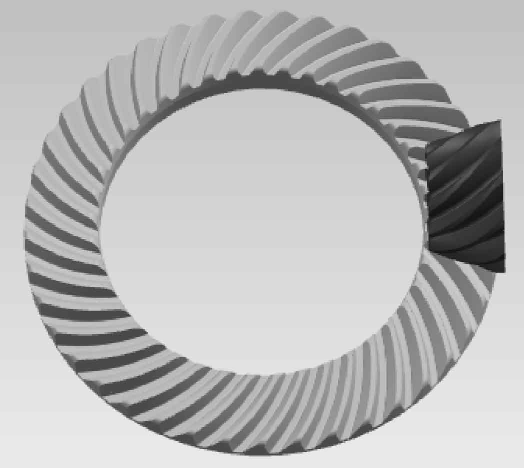
Using the established tooth patch model (Fig. 3), trim the wheel blank model through the “trim body” command: take the wheel blank model as the entity and the tooth patch as the tool body, cut a tooth groove on the wheel blank, and the result is as shown in Fig. 7. Then, conduct a circular array of the tooth groove surface through the “pattern surface” command in the “instance feature” tab to obtain the model of the large gear of spiral bevel gear, As shown in Figure 8.
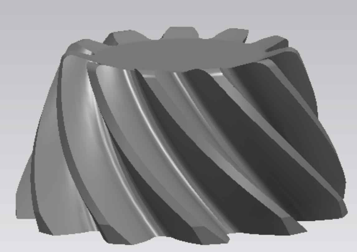
Similar to the drawing method of the big wheel, draw the model of the small wheel, as shown in Figure 9.
The large and small wheel models are built through trimming to meet the process requirements of forging. The size of the central hole of the model is adjusted by the size of the wheel blank model. For precision forging, to ensure the accuracy of the forging is to ensure the accuracy of the die cavity. Using the Boolean operation in UG software, the shape of the standard spiral bevel gear is accurately copied to the die to form the die cavity, This method has the advantages of simple operation and accurate tooth profile, which is suitable for the initial production of the die, and then modify it according to the problems in simulation or production, so as to gradually form the die model and die concrete with better performance.
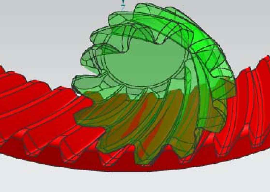
Assemble the established large and small wheels, and constrain the spiral bevel gear pair with installation distance. The constrained gear pair is shown in Figure 10.
By adjusting the distance between the two tooth surfaces, the theoretical contact area of spiral bevel gear pair is obtained, as shown in FIG. 11.