
I study the meshing behavior of complex modified face gear pairs because the face gear drive is one of the most promising solutions for high-power-density, low-noise, and lightweight transmission systems. In my work, a face gear pair consists of a face gear and a cylindrical pinion. The face gear tooth surface is generated by a virtual shaper cutter, and the resulting geometry is strongly asymptotic along the tooth width. This asymptotic character makes the face gear tooth surface difficult to modify and difficult to model accurately. I therefore propose an active modification method that introduces modification curve parameters into the face gear tooth surface. The method is combined with numerical modeling, tooth contact analysis, loaded tooth contact analysis, a neural-network prediction model, a hypervolume-based multi-objective optimizer, and a comprehensive decision method. I use these tools to reveal how modification parameters affect contact path, transmission error, and contact stress, and to obtain an optimized face gear pair with improved meshing characteristics.
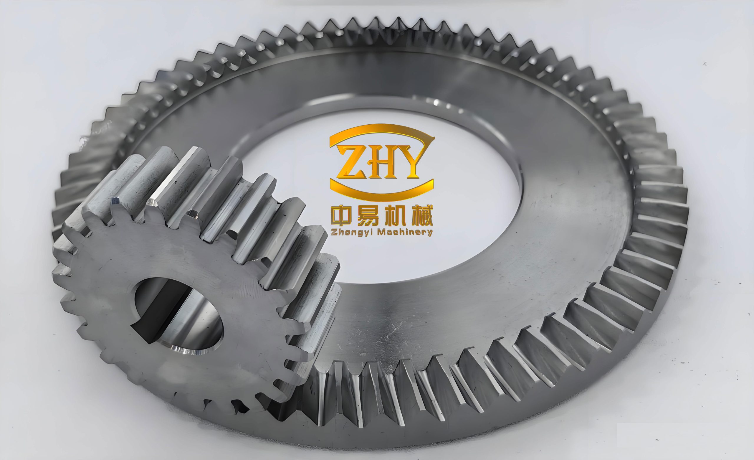
My research begins from the geometric generation of the face gear. The face gear working surface is the envelope of the shaper cutter tooth surface. The transition surface is generated by the tip edge of the shaper cutter and does not participate in meshing. The working surface and the transition surface are connected smoothly along a transition curve. Because the face gear tooth is wider at the inner end and narrower at the outer end, the contact path and the load distribution are sensitive to small changes in tooth surface geometry. I therefore treat the face gear tooth surface as a free-form surface after modification and represent it by numerical point clouds rather than by a simple analytical expression.
I define the shaper cutter tooth surface by an involute parameter and a tooth-width parameter. Let the shaper cutter surface be expressed as
$$ \mathbf{r}_s(u_s,\theta_s)= \begin{bmatrix} x_s(u_s,\theta_s)\\ y_s(u_s,\theta_s)\\ z_s(u_s,\theta_s) \end{bmatrix} = \begin{bmatrix} r_b\left[\cos(\theta_s+\theta_{os})+(\theta_s+\theta_{os})\sin(\theta_s+\theta_{os})\right]\\ r_b\left[\sin(\theta_s+\theta_{os})-(\theta_s+\theta_{os})\cos(\theta_s+\theta_{os})\right]\\ u_s \end{bmatrix}, $$
where \(r_b\) is the base radius of the shaper cutter, \(\theta_s\) is the involute roll angle, \(\theta_{os}\) is the angular parameter at the reference point, and \(u_s\) is the axial parameter along the shaper cutter tooth width. The upper and lower signs correspond to the two flanks of the face gear tooth. I then transform this surface into the face gear coordinate system through a sequence of rotations and translations. The transformation matrix from the shaper cutter frame to the face gear frame is written as
$$ \mathbf{M}_{2s}(\phi_s)= \begin{bmatrix} \sin\phi_s & \cos\phi_s & 0 & 0\\ -\cos\phi_s\sin\gamma & \sin\phi_s\sin\gamma & \cos\gamma & 0\\ -\cos\phi_s\cos\gamma & \sin\phi_s\cos\gamma & \sin\gamma & 0\\ 0 & 0 & 0 & 1 \end{bmatrix}, $$
where \(\phi_s\) is the shaper cutter rotation angle and \(\gamma\) is the shaft angle. For a face gear pair with orthogonal axes, \(\gamma=90^\circ\). The generated family of surfaces is
$$ \mathbf{r}_2(u_s,\theta_s,\phi_s)=\mathbf{M}_{2s}(\phi_s)\mathbf{r}_s(u_s,\theta_s). $$
The meshing equation that eliminates the envelope parameter is
$$ f(u_s,\theta_s,\phi_s)=\mathbf{n}_s\cdot\mathbf{v}_s^{(2)}=0, $$
where \(\mathbf{n}_s\) is the normal vector of the shaper cutter surface and \(\mathbf{v}_s^{(2)}\) is the relative velocity between the shaper cutter and the face gear. After simplification, the meshing equation for the face gear becomes
$$ f(u_s,\theta_s,\phi_s)=r_b-u_s\cos\theta_s+m_{2s}\phi_s\cos\theta_s=0, $$
where \(m_{2s}=N_s/N_2\), \(N_s\) is the shaper cutter tooth number, and \(N_2\) is the face gear tooth number. The working surface of the face gear follows from
$$ \begin{cases} \mathbf{r}_2=\mathbf{M}_{2s}(\phi_s)\mathbf{r}_s(u_s,\theta_s),\\ f(u_s,\theta_s,\phi_s)=0. \end{cases} $$
The transition curve is obtained from the tip edge of the shaper cutter. Its involute parameter is
$$ \theta_s^*=\sqrt{r_a^2-r_b^2}, $$
where \(r_a\) is the tip radius of the shaper cutter. Substituting \(\theta_s^*\) into the meshing equation gives the transition curve, which connects the working surface to the root region. I use the transition curve only for geometric closure and stress continuity, not for meshing contact. The basic geometric parameters that I use for the face gear pair are summarized in Table 1.
| Parameter | Symbol | Value |
|---|---|---|
| Pinion tooth number | \(N_1\) | 21 |
| Shaper cutter tooth number | \(N_s\) | 23 |
| Face gear tooth number | \(N_2\) | 48 |
| Pressure angle | \(\alpha\) | \(25^\circ\) |
| Shaft angle | \(\gamma\) | \(90^\circ\) |
| Module | \(m\) | 3.9 mm |
| Inner radius | \(L_1\) | 180 mm |
| Outer radius | \(L_2\) | 200 mm |
After establishing the standard face gear tooth surface, I introduce modification. The modification method is inspired by crowning of cylindrical gears, but the gradual variation of the face gear tooth surface requires additional control. I divide the modification into tooth-profile modification and tooth-width modification. The pinion tooth surface is modified by a crowning curve, while the face gear tooth surface is modified by a superimposed modification curve. The modification amount on the pinion is
$$ \Delta c=\alpha_0 u^2, $$
where \(\alpha_0\) is the parabolic crowning coefficient and \(u\) is the position parameter along the tooth width. The corresponding coordinate offsets are
$$ \begin{cases} \Delta x=\Delta c\cos(\theta_s’+\theta_{os}’),\\ \Delta y=\Delta c\sin(\theta_s’+\theta_{os}’). \end{cases} $$
For the face gear, I discretize the tooth surface into a grid of points. At each point, I compute the normal vector and superimpose a modification amount along the normal direction. The modified point is
$$ \mathbf{r}_m’=\mathbf{r}_m+\Delta\delta_m\mathbf{n}_m, $$
where \(\mathbf{r}_m\) is the standard face gear tooth surface point, \(\mathbf{n}_m\) is the unit normal vector, and \(\Delta\delta_m\) is the modification amount. To capture the gradual variation of the face gear, I introduce two modification curve parameters \(K_1\) and \(K_2\). The modification amount is defined separately for the outer half and the inner half of the tooth width:
$$ \Delta\delta_m= \begin{cases} \alpha_1 u_m^{K_1}, & 0.5\le K_1\le 1,\\ \alpha_2 u_m^{K_2}, & 1\le K_2\le 1.5. \end{cases} $$
Here \(u_m\) is the position parameter along the face gear tooth width. The outer half uses \(K_1\) in the range from 0.5 to 1, which removes less material and prevents edge contact. The inner half uses \(K_2\) in the range from 1 to 1.5, which removes more material and distributes the contact stress more evenly. This design allows the face gear tooth surface to transition smoothly from the outer end to the inner end. The modification parameter ranges are listed in Table 2.
| Modification parameter | Symbol | Range |
|---|---|---|
| Pinion profile modification | \(C_t\) | 0.01–0.05 mm |
| Pinion widthwise modification | \(C_p\) | 0.01–0.05 mm |
| Face gear profile modification | \(C_{tf}\) | 0.01–0.05 mm |
| Face gear widthwise modification | \(C_{pf}\) | 0.01–0.05 mm |
| Outer modification curve parameter | \(K_1\) | 0.5–1.0 |
| Inner modification curve parameter | \(K_2\) | 1.0–1.5 |
To build a three-dimensional model of the modified face gear pair, I use a numerical modeling procedure. I discretize the pinion tooth surface and the face gear tooth surface into point clouds. The face gear tooth surface is divided into \(n\) intervals in the involute direction and \(n\) intervals in the width direction, producing an \(n\times n\) grid. At each grid point, I calculate the modified coordinates and the normal vector. I then export the point cloud and construct the single-tooth surface. Revolving the single tooth around the face gear axis produces the complete face gear. A similar procedure is applied to the pinion. The pinion and the face gear are finally assembled with the same shaft angle and center position. This numerical model provides a reliable geometric basis for the subsequent meshing analysis.
The first meshing analysis that I perform is tooth contact analysis. The face gear pair must satisfy continuous tangency at the contact point. At any instant, the position vectors of the two contacting surfaces are identical, and their normal vectors are collinear. I write the contact equations as
$$ \begin{cases} \mathbf{r}_1^{(1)}(u_1,\theta_1,\phi_1)=\mathbf{r}_2^{(2)}(u_2,\theta_2,\phi_2),\\ \mathbf{n}_1^{(1)}(u_1,\theta_1,\phi_1)=\lambda\mathbf{n}_2^{(2)}(u_2,\theta_2,\phi_2),\\ f(u_s,\theta_s,\phi_s)=0. \end{cases} $$
Because the normal vector has unit length, collinearity provides only two independent scalar equations. The position equality provides three scalar equations. Together with the face gear generation constraint, the system has five independent equations. I treat the pinion rotation angle as the input parameter and solve the nonlinear system numerically. The solution gives a sequence of contact points on the face gear tooth surface. I then evaluate the contact path and the transmission error. The transmission error is defined as
$$ \Delta\phi_2=(\phi_2-\phi_2^0)-\frac{N_1}{N_2}(\phi_1-\phi_1^0), $$
where \(\phi_1^0\) and \(\phi_2^0\) are the initial rotation angles. I also use a contact position parameter to quantify whether the contact path is centered on the face gear tooth surface. The contact position parameter is
$$ CP=\frac{L_oL_1h_oh_1}{B_fh_f}+\frac{L_oL_2h_oh_2}{B_fh_f}+\frac{L_oL_3h_oh_3}{B_fh_f}, $$
where \(L_o\) and \(h_o\) are the coordinates of the tooth center, \(L_1,L_2,L_3\) and \(h_1,h_2,h_3\) are the coordinates of the entry point, middle point, and exit point of the contact path, and \(B_f\) and \(h_f\) are the face gear tooth width and tooth height. A smaller \(CP\) indicates that the contact path is closer to the middle of the face gear tooth. The standard face gear pair without modification has a relatively large contact position parameter and a noticeable edge contact tendency. Its transmission error is periodic and reaches a peak when the contact moves from one tooth pair to the next.
I then study how each modification parameter affects the contact path. I select five levels for each parameter. The results show that increasing the pinion widthwise modification moves the contact path toward the middle of the face gear tooth. Increasing the pinion profile modification shifts the contact path from the inner tip region toward the outer root region. The face gear widthwise modification has a similar effect to the pinion widthwise modification, moving the contact path toward the middle. The face gear profile modification shifts the contact path in a manner similar to the pinion profile modification. For the modification curve parameters, the contact path first moves toward the middle and then moves toward the edge as \(K_1\) or \(K_2\) increases. The detailed trends are summarized in Table 3.
| Parameter | Effect on contact path | Effect on transmission error | Effect on contact stress |
|---|---|---|---|
| \(C_p\) | Moves toward the middle | First decreases, then increases | First decreases, then increases |
| \(C_t\) | Shifts from inner tip to outer root | Decreases | Decreases |
| \(C_{pf}\) | Moves toward the middle | First decreases, then increases | First decreases, then increases |
| \(C_{tf}\) | Shifts from inner tip to outer root | Decreases | Decreases |
| \(K_1\) | First middle, then edge | First decreases, then increases | First decreases, then increases |
| \(K_2\) | First middle, then edge | First decreases, then increases | First decreases, then increases |
The transmission error curves remain periodic for all modification parameters. For the pinion widthwise modification, the amplitude of the transmission error first decreases and then increases as the modification amount increases. A minimum is reached when the modification amount is about 0.03 mm. For the pinion profile modification, the transmission error amplitude decreases monotonically and reaches its lowest value at 0.05 mm. The face gear widthwise modification shows a similar non-monotonic trend, with a minimum near 0.03 mm. The face gear profile modification again decreases the transmission error amplitude as the modification amount increases. For the modification curve parameters, the transmission error amplitude first decreases and then increases, with minima near \(K_1=0.7\) and \(K_2=1.3\). These trends show that the face gear pair has an optimal region rather than a single globally optimal parameter value.
I next perform loaded tooth contact analysis to evaluate contact stress under torque. I import the assembled face gear pair into a finite element environment, generate a mesh, and refine the tooth contact region. The pinion and face gear are treated as elastic bodies. The material density is \(7.85\times 10^3\ \mathrm{kg/m^3}\), the elastic modulus is \(2.1\times 10^5\ \mathrm{MPa}\), and the Poisson ratio is 0.3. The contact between the pinion and the face gear is defined as a surface-to-surface frictional contact with a friction coefficient of 0.1. The pinion rotation and the face gear rotation are constrained so that only the rotational degrees of freedom remain active. A torque of 1000 N·m is applied to the pinion, and the resisting torque on the face gear is determined from the tooth number ratio as
$$ T_2=\frac{N_2}{N_1}T_1. $$
The finite element setup is summarized in Table 4. The mesh is refined near the contact path because the stress gradient is high in that region. The overall mesh size controls the computational cost, while the local mesh size controls the accuracy of the contact stress. I use the same procedure for the standard face gear pair and for each modified face gear pair.
| Item | Value or setting |
|---|---|
| Material density | \(7.85\times 10^3\ \mathrm{kg/m^3}\) |
| Elastic modulus | \(2.1\times 10^5\ \mathrm{MPa}\) |
| Poisson ratio | 0.3 |
| Contact type | Surface-to-surface |
| Friction coefficient | 0.1 |
| Input torque | 1000 N·m |
| Pinion rotation range | \(30^\circ\) |
| Increment step | \(1.5^\circ\) |
The loaded tooth contact analysis shows that the standard face gear pair has a high contact stress near the entry and exit regions. The maximum contact stress of the standard face gear pair is about 576.25 MPa, and the minimum contact stress during the meshing cycle is about 312.55 MPa. The stress concentration is caused by the large relative curvature near the edges and by the edge contact tendency of the unmodified face gear. After modification, the contact stress decreases significantly. For the pinion widthwise modification, the maximum contact stress first decreases and then increases, with a minimum near 0.03 mm. For the pinion profile modification, the maximum contact stress decreases as the modification amount increases. The face gear widthwise modification also produces a minimum near 0.03 mm, and the face gear profile modification reduces the contact stress as the modification amount increases. The modification curve parameters \(K_1\) and \(K_2\) have a strong influence: the maximum contact stress reaches a minimum near \(K_1=0.7\) and \(K_2=1.3\). Table 5 lists representative maximum contact stresses for different parameter studies.
| Study case | Parameter | Best level | Maximum contact stress |
|---|---|---|---|
| Pinion widthwise modification | \(C_p\) | 0.03 mm | 467.62 MPa |
| Pinion profile modification | \(C_t\) | 0.05 mm | 443.57 MPa |
| Face gear widthwise modification | \(C_{pf}\) | 0.03 mm | 448.98 MPa |
| Face gear profile modification | \(C_{tf}\) | 0.05 mm | 426.68 MPa |
| Outer modification curve parameter | \(K_1\) | 0.7 | 341.39 MPa |
| Inner modification curve parameter | \(K_2\) | 1.3 | 328.67 MPa |
Because the modification parameters interact with each other, single-variable studies cannot fully describe the face gear pair behavior. I therefore use Latin hypercube sampling to generate a set of sample points in the six-dimensional modification parameter space. For each sample, I calculate the contact position parameter, transmission error, and maximum contact stress by tooth contact analysis and loaded tooth contact analysis. I use 100 samples. The sample space is uniform and covers the entire feasible region. A subset of the sample data is shown in Table 6. I also perform five-fold cross validation to verify the consistency of the sampled data. The mean square errors of the cross-validation are all less than 0.01, which indicates that the sampling strategy is reliable.
| Sample | \(C_t\) | \(C_p\) | \(C_{tf}\) | \(C_{pf}\) | \(K_1\) | \(K_2\) | \(CP\) | \(TE\) | \(\sigma_c\) |
|---|---|---|---|---|---|---|---|---|---|
| 1 | 0.0386 | 0.0382 | 0.0108 | 0.0203 | 0.9185 | 1.3256 | 2.0701 | 1.3582 | 445.81 |
| 2 | 0.0260 | 0.0363 | 0.0377 | 0.0358 | 0.8445 | 1.0274 | 2.0309 | 2.0892 | 482.39 |
| 3 | 0.0114 | 0.0313 | 0.0451 | 0.0354 | 0.9931 | 1.2181 | 3.4370 | 2.8576 | 517.80 |
| 4 | 0.0138 | 0.0194 | 0.0297 | 0.0378 | 0.6089 | 1.2506 | 1.6050 | 2.3686 | 460.58 |
| 5 | 0.0130 | 0.0308 | 0.0364 | 0.0451 | 0.8268 | 1.3688 | 1.9260 | 1.6248 | 394.99 |
| 6 | 0.0316 | 0.0436 | 0.0355 | 0.0394 | 0.6861 | 1.1092 | 3.8496 | 2.2867 | 439.26 |
| 100 | 0.0182 | 0.0274 | 0.0199 | 0.0119 | 0.5728 | 1.2467 | 0.6251 | 1.4180 | 426.83 |
The coupling effects are visualized by a heat map of parameter influence. The influence ranking on the contact position parameter is \(K_1>K_2>C_{pf}>C_{tf}>C_p>C_t\). The influence ranking on the transmission error is \(C_{pf}>C_{tf}>K_1>K_2>C_t>C_p\). The influence ranking on the contact stress is \(C_{tf}>K_1>K_2>C_{pf}>C_t>C_p\). No single parameter dominates all meshing characteristics. This confirms that the face gear pair modification problem is multi-dimensional and nonlinear. A simple linear regression or a one-factor-at-a-time method cannot identify the best combination. I therefore build a machine-learning prediction model and combine it with a multi-objective optimizer.
I use a back-propagation neural network to map the modification parameters to the meshing characteristics. The inputs are \(C_t\), \(C_p\), \(C_{tf}\), \(C_{pf}\), \(K_1\), and \(K_2\). The outputs are \(CP\), \(TE\), and \(\sigma_c\). I normalize the inputs and outputs to the interval \([0,1]\). The normalization formula is
$$ x^*=\frac{x-x_{\min}}{x_{\max}-x_{\min}}, $$
and the inverse normalization formula is
$$ y=y^*(x_{\max}-x_{\min})+x_{\min}. $$
The hidden layer neurons are determined by
$$ l=\sqrt{p+n}+k, $$
where \(p\) is the number of input neurons, \(n\) is the number of output neurons, and \(k\) is an integer between 1 and 10. The network is trained with a maximum of 1000 iterations, a target error of \(10^{-6}\), and a learning rate of 0.01. The forward propagation is
$$ H_j=f\left(\sum_{i=1}^{n}w_{ij}x_i-a_j\right), $$
$$ Y_k=\sum_{j=1}^{l}H_jw_{jk}-b_k, $$
where \(w_{ij}\) and \(w_{jk}\) are weights, \(a_j\) and \(b_k\) are thresholds, and \(f\) is the activation function. The weights and thresholds are updated by error back-propagation. Although a standard back-propagation neural network can approximate nonlinear functions, it can converge slowly and fall into local optima. To improve the prediction accuracy, I use a Newton-Raphson-based optimizer to optimize the initial weights and thresholds of the network. The resulting model is called NRBPNN. The optimizer explores the solution space with a Newton-Raphson search rule and a trap-avoidance operator. I use
$$ X_{n}^{t+1}=r_1X_{n}^{t}+r_2X_{b}^{t}+(1-r_2)X_{n}^{t}-r_3X_{w}^{t}, $$
where \(X_b\) is the best position, \(X_w\) is the worst position, and \(r_1,r_2,r_3\) are random numbers. The trap-avoidance mechanism compares a random number with a threshold and either keeps the best position or generates a new candidate. This mechanism increases population diversity and reduces the risk of premature convergence. The prediction performance is evaluated by mean absolute percentage error, root mean square error, and coefficient of determination:
$$ MAPE=\frac{100\%}{n}\sum_{i=1}^{n}\left|\frac{y_i-\hat{y}_i}{y_i}\right|, $$
$$ RMSE=\sqrt{\frac{1}{n}\sum_{i=1}^{n}(y_i-\hat{y}_i)^2}, $$
$$ R^2=1-\frac{\sum_{i=1}^{n}(y_i-\hat{y}_i)^2}{\sum_{i=1}^{n}(y_i-\bar{y}_i)^2}. $$
The comparison between the standard back-propagation neural network and the NRBPNN model is shown in Table 7. For all three outputs, the NRBPNN model has lower MAPE and RMSE and higher \(R^2\). The NRBPNN model therefore provides a more accurate and more interpretable mapping from the modification parameters to the meshing characteristics of the face gear pair.
| Output | Model | MAPE | RMSE | \(R^2\) |
|---|---|---|---|---|
| \(CP\) | NRBPNN | 0.237 | 0.423 | 0.941 |
| \(CP\) | BPNN | 0.395 | 0.649 | 0.828 |
| \(TE\) | NRBPNN | 0.130 | 0.219 | 0.961 |
| \(TE\) | BPNN | 0.221 | 0.337 | 0.923 |
| \(\sigma_c\) | NRBPNN | 0.035 | 19.54 | 0.947 |
| \(\sigma_c\) | BPNN | 0.057 | 30.018 | 0.886 |
After obtaining the NRBPNN prediction model, I formulate the modification optimization problem. The objective is to minimize the contact position parameter, the transmission error, and the maximum contact stress. The objective vector is
$$ \min \mathbf{F}(C_t,C_p,C_{tf},C_{pf},K_1,K_2)= \begin{bmatrix} CP(C_t,C_p,C_{tf},C_{pf},K_1,K_2)\\ TE(C_t,C_p,C_{tf},C_{pf},K_1,K_2)\\ \sigma_c(C_t,C_p,C_{tf},C_{pf},K_1,K_2) \end{bmatrix}. $$
The constraints are the ranges of the modification parameters:
$$ \begin{cases} 0.01\le C_t\le 0.05,\\ 0.01\le C_p\le 0.05,\\ 0.01\le C_{tf}\le 0.05,\\ 0.01\le C_{pf}\le 0.05,\\ 0.5\le K_1\le 1.0,\\ 1.0\le K_2\le 1.5. \end{cases} $$
I solve this multi-objective problem with a hypervolume estimation algorithm. The algorithm evaluates the hypervolume contribution of each non-dominated solution and selects offspring according to that contribution. The hypervolume contribution of a solution \(x_i\) relative to a reference point \(r\) is
$$ HV(x_i)=\sum_{j=1,x_j\in F\setminus\{x_i\}}^{M}Volume\left(\prod_{m=1}^{M}\left(r_m-f_m(x_j)\right)\right), $$
where \(M\) is the number of objectives and \(F\) is the non-dominated set. The selection probability of a solution is proportional to its hypervolume contribution:
$$ P(x_i)=\frac{HV(x_i)}{\sum_{j=1}^{N}HV(x_j)}. $$
New individuals are generated by crossover and mutation. I use a population size of 100 and a maximum of 90 iterations. The optimizer produces a Pareto set that covers the trade-off among contact position, transmission error, and contact stress. Because the Pareto set contains many non-dominated solutions, I use a comprehensive decision method to select the final face gear modification scheme. I combine the analytic hierarchy process with the technique for order preference by similarity to an ideal solution. The decision matrix is
$$ D= \begin{bmatrix} x_{11} & x_{12} & x_{13}\\ x_{21} & x_{22} & x_{23}\\ \vdots & \vdots & \vdots\\ x_{m1} & x_{m2} & x_{m3} \end{bmatrix}, $$
where each row is a candidate face gear modification scheme and each column is a meshing characteristic. I normalize the decision matrix by
$$ r_{ij}=\frac{x_{ij}}{\sqrt{\sum_{i=1}^{m}x_{ij}^2}}. $$
I construct a pairwise comparison matrix for the three objectives and obtain the weights \(0.2326\), \(0.3023\), and \(0.4651\) for \(CP\), \(TE\), and \(\sigma_c\). I then calculate the distances to the ideal and negative-ideal solutions:
$$ d_i^+=\sqrt{\sum_{j=1}^{n}w_j(r_{ij}-r_j^+)^2}, $$
$$ d_i^-=\sqrt{\sum_{j=1}^{n}w_j(r_{ij}-r_j^-)^2}. $$
The relative closeness is
$$ C_i=\frac{d_i^-}{d_i^++d_i^-}. $$
A larger \(C_i\) means a better face gear modification scheme. The top ten solutions from the Pareto set are listed in Table 8. I validate these candidates by rebuilding the face gear pair and performing tooth contact analysis and loaded tooth contact analysis. The differences between the predicted and simulated values are small. The maximum difference in contact position is about 2.2%, the maximum difference in transmission error is about 9.6%, and the maximum difference in contact stress is about 4.5%. These differences confirm that the NRBPNN model and the HYPE optimizer are effective for the face gear pair.
| Rank | \(C_t\) | \(C_p\) | \(C_{tf}\) | \(C_{pf}\) | \(K_1\) | \(K_2\) | \(CP\) | \(TE\) | \(\sigma_c\) | \(C_i\) |
|---|---|---|---|---|---|---|---|---|---|---|
| 1 | 0.0132 | 0.0331 | 0.0108 | 0.0331 | 0.712 | 1.293 | 1.500 | 0.314 | 297.05 | 0.942 |
| 2 | 0.0130 | 0.0352 | 0.0113 | 0.0346 | 0.733 | 1.304 | 1.494 | 0.323 | 298.08 | 0.938 |
| 3 | 0.0165 | 0.0338 | 0.0124 | 0.0327 | 0.747 | 1.339 | 1.482 | 0.322 | 301.45 | 0.936 |
| 4 | 0.0148 | 0.0341 | 0.0113 | 0.0343 | 0.716 | 1.283 | 1.471 | 0.340 | 300.76 | 0.935 |
| 5 | 0.0136 | 0.0349 | 0.0124 | 0.0345 | 0.694 | 1.312 | 1.479 | 0.332 | 302.60 | 0.934 |
| 6 | 0.0156 | 0.0346 | 0.0132 | 0.0351 | 0.670 | 1.333 | 1.490 | 0.342 | 300.25 | 0.932 |
| 7 | 0.0152 | 0.0355 | 0.0129 | 0.0358 | 0.706 | 1.347 | 1.463 | 0.329 | 306.02 | 0.928 |
| 8 | 0.0161 | 0.0364 | 0.0124 | 0.0354 | 0.671 | 1.323 | 1.457 | 0.343 | 304.68 | 0.924 |
| 9 | 0.0142 | 0.0360 | 0.0136 | 0.0364 | 0.709 | 1.338 | 1.453 | 0.348 | 306.57 | 0.922 |
| 10 | 0.0159 | 0.0348 | 0.0142 | 0.0362 | 0.686 | 1.316 | 1.442 | 0.351 | 308.39 | 0.917 |
I select the first-ranked solution as the optimal face gear modification scheme. The optimal modification parameters are \(C_t=0.0132\) mm, \(C_p=0.0331\) mm, \(C_{tf}=0.0108\) mm, \(C_{pf}=0.0331\) mm, \(K_1=0.71\), and \(K_2=1.29\). I rebuild the optimized face gear pair and compare it with the unmodified face gear pair. The contact path moves toward the middle of the face gear tooth, and edge contact is suppressed. The contact position parameter decreases from 4.15 to 1.50. The transmission error decreases from \(2.89”\) to \(0.314”\). The maximum contact stress decreases from 566.30 MPa to 292.33 MPa. These improvements show that the proposed modification method and optimization framework can significantly improve the meshing characteristics of the face gear pair. The comparison is given in Table 9.
| Meshing characteristic | Unmodified face gear pair | Optimized face gear pair | Improvement |
|---|---|---|---|
| Contact position parameter \(CP\) | 4.15 | 1.50 | 63.9% reduction |
| Transmission error \(TE\) | \(2.89”\) | \(0.314”\) | 89.1% reduction |
| Maximum contact stress \(\sigma_c\) | 566.30 MPa | 292.33 MPa | 48.4% reduction |
The optimized modification parameters can be transferred directly to manufacturing. The two modification curve parameters \(K_1\) and \(K_2\) provide independent control of the outer and inner halves of the face gear tooth. This is important because the face gear tooth width changes continuously from the inner end to the outer end. A conventional crowning curve cannot represent this gradual change with sufficient accuracy. By introducing \(K_1\) and \(K_2\), I can tune the face gear tooth surface so that the outer region removes less material and the inner region removes more material. The result is a smooth transition, a centered contact path, a smaller transmission error, and a lower contact stress. The method also reduces the need for trial-and-error adjustment during manufacturing.
I also examine the limitations of my study. The prediction model is trained on a finite number of samples. Although Latin hypercube sampling covers the design space efficiently, the accuracy of the NRBPNN model depends on the sample distribution. The loaded tooth contact analysis is based on finite element simulation, which is computationally expensive. The optimization currently considers only contact position, transmission error, and contact stress. Future work can include manufacturing cost, grinding efficiency, tool wear, and dynamic response. The face gear pair parameters are fixed in this study, and the influence of tooth number, module, pressure angle, and shaft angle on the modified face gear pair should be studied further. The machining feasibility of the modified face gear tooth surface should also be investigated from the perspectives of tool design and path planning.
In summary, I propose an integrated framework for the analysis and optimization of a complex modified face gear pair. The framework includes a face gear tooth surface generation model, an active modification method with modification curve parameters, a numerical three-dimensional model, a tooth contact analysis model, a loaded tooth contact analysis model, a Latin hypercube sampling scheme, an NRBPNN prediction model, a HYPE multi-objective optimization model, and an AHP-TOPSIS decision method. The face gear pair is studied as a coupled nonlinear system. The contact path, transmission error, and contact stress are used as the meshing characteristics. The modification parameters include pinion profile modification, pinion widthwise modification, face gear profile modification, face gear widthwise modification, and two modification curve parameters. The optimal solution reduces the contact position parameter from 4.15 to 1.50, reduces the transmission error from \(2.89”\) to \(0.314”\), and reduces the maximum contact stress from 566.30 MPa to 292.33 MPa. The optimized face gear pair therefore has a more centered contact path, a smoother transmission, and a lower contact stress. This work provides a practical and theoretical basis for the design of high-performance face gear drives.