With the increase of aircraft engine thrust and thrust to weight ratio, it is required that the power and speed transmitted by the spiral bevel gear continue to increase, and the temperature of the meshing surface of the spiral bevel gear also needs to be continuously raised. This puts forward more stringent requirements for the materials used to manufacture spiral bevel gears. Spiral bevel gears are widely used in the central transmission system of engines due to their advantages such as smooth transmission, strong load-bearing capacity, and compact structure. The central transmission spiral bevel gear is the hub of power transmission, and once it fails, it will cause the entire transmission system to lose function and interrupt flight missions.
The failure forms of aviation spiral bevel gears often manifest as tooth surface pitting, bonding, wear, plastic deformation, and fracture. Scholars at home and abroad have conducted in-depth research on multiple fracture faults of spiral bevel gears that occur during engine operation. Pierre et al. analyzed the fracture fault of the spur bevel gear in the gearbox of the GE 90-11B engine and believed that it was caused by the combined effect of residual tensile stress and working stress generated by local decarburization. Subsequently, shot peening measures were taken to solve the problem; Chen Conghui and Song Lemin identified three failure faults of the central transmission spiral bevel gears in turbojet engines. After theoretical analysis and experimental measurements, they believed that the cause of the failure was resonance failure. Later, by modifying the structure, resonance was avoided. However, there have been no relevant reports on the analysis of fatigue failure caused by abnormal loads on the teeth of spiral bevel gears due to edge contact, and the differences between the failure modes and traditional resonance are difficult to define.
During the central transmission debugging test, a tooth fracture fault occurred in the active spiral bevel gear. The faulty spiral bevel gear was prepared using the third-generation low-carbon high alloy steel 15Cr14Co12Mo5Ni2 material, which has high temperature resistance, corrosion resistance, and excellent strength and toughness. The research by Trivedi and Yuan Xiaohong showed that the surface of this material has good wear resistance and high contact fatigue performance after carburization. Similar faults first occurred on this material’s spiral bevel gear, so the failure mechanism was explored, It has certain reference significance for further improving the design and process.
ZHY Gear analyzes faulty spiral bevel gears from multiple aspects such as macroscopic inspection, fracture analysis, tissue inspection, composition analysis, hardness testing, meshing imprint simulation and verification, in order to clarify their failure modes and causes, and propose corresponding improvement suggestions.
1. Experimental process and results
1.1 Macroscopic examination
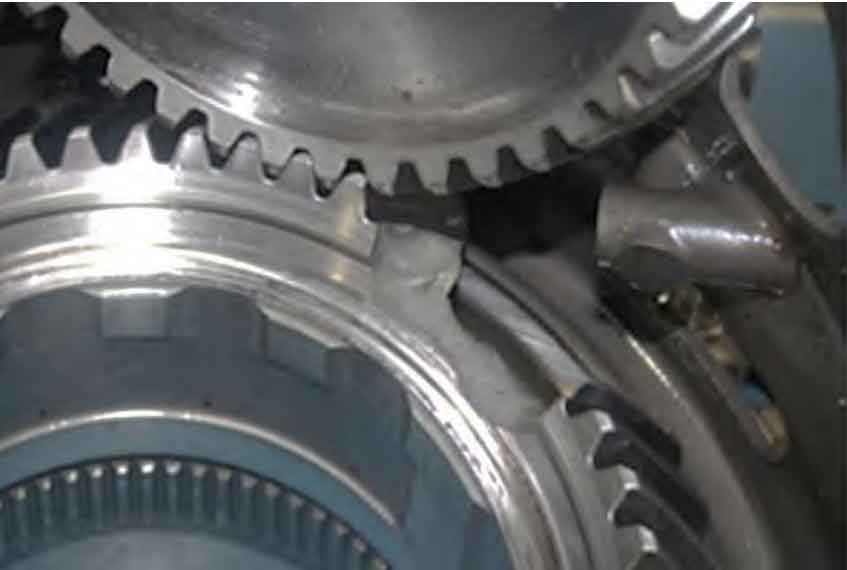
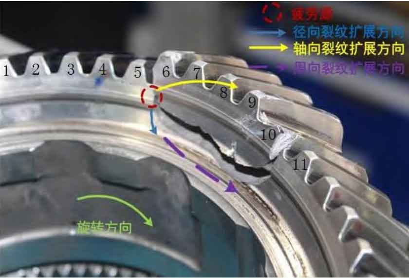
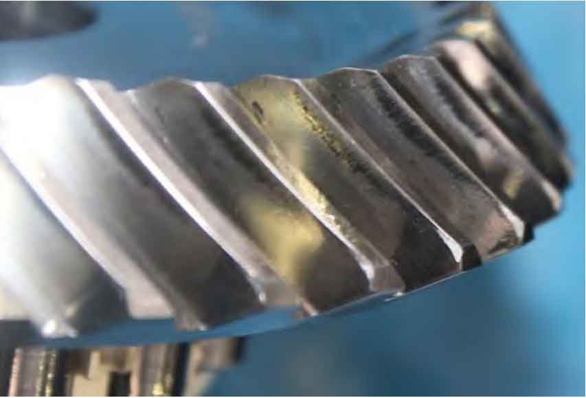
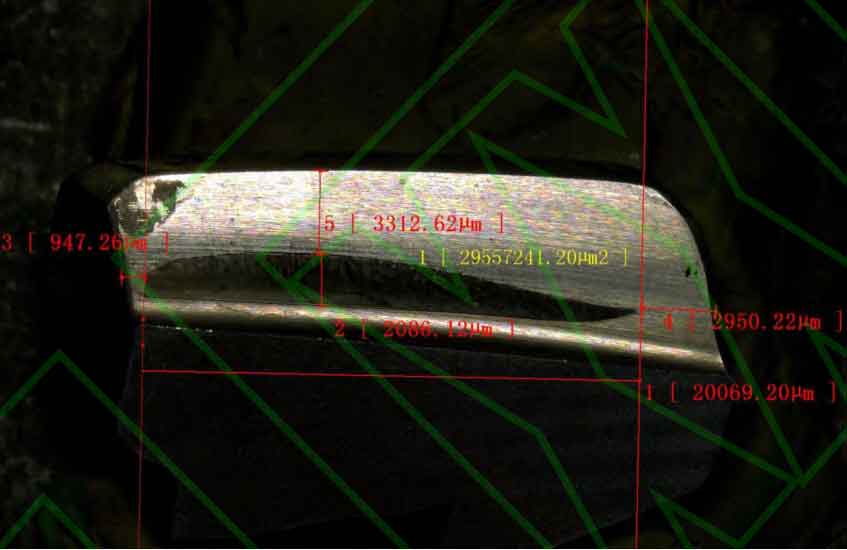
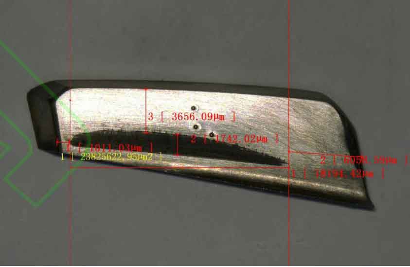
The macroscopic morphology of the faulty spiral bevel gear is shown in Figure 1. From the figure, it can be seen that the active spiral bevel gear has broken four complete teeth at the belly plate below the teeth, and after splicing, it is generally intact, while the driven spiral bevel gear is overall intact. The concave surface of the active spiral bevel gear and the convex surface of the driven spiral bevel gear serve as the working surfaces of the gear pair, and contact marks are clearly visible on both sides of the working surfaces, with a slender eyebrow shape. The contact marks on the entire circumference of the faulty active spiral bevel gear are uneven, leaning towards the small end side and close to the tooth bottom. The morphology characteristics of the marks can be roughly divided into three categories (as shown in Figure 2). The first type is 5 # tooth (crack tooth), with the narrowest imprint width of about 1.0 mm, a longer length of about 23.0mm, and a distance of about 5.0 mm from the tooth top; The second type is 6 # to 9 # teeth (tooth loss). The width of the imprint is about 2.0 mm, the length is about 20.0mm, and the distance from the tooth tip is about 5.3 mm; The third type is the remaining teeth (excluding teeth 5 # to 9 #), with an imprint width of approximately 1.7 mm and a length of approximately 18.0 mm, and a distance of approximately 5.3 mm from the tooth tip. The contact marks on the driven spiral bevel gear are distributed at the small tooth tip, and the marks are incomplete and partially exceed the working surface.
1.2 Fracture analysis
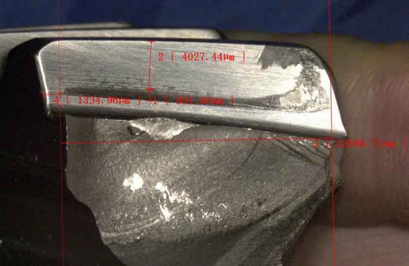
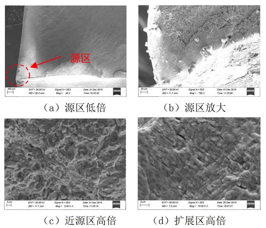
The tooth loss fracture of the faulty active spiral bevel gear can be divided into radial 1, circumferential, and radial 2 fractures. The radial 1 and circumferential fractures are more delicate, and fatigue curves and radial edges are clearly visible, indicating that the tooth loss fracture is fatigue property, as shown in Figure 3 (a); Judging from the direction of the fatigue arc and radiating edge, fatigue originates from the corner of the transition between the small end face and the root of the tooth convex surface, as shown in Figure 3 (b); The circumferential fracture is formed by radial 1 crack fatigue propagation, while the radial 2 fracture is relatively rough, with an area smaller than 20% of the entire area of the falling block fracture. It should be an instantaneous fracture formed in the later stage of fatigue propagation. From the figure, it can be seen that the crack first extends from the small end face to the large end face, then simultaneously along the axial and radial directions. After reaching the junction of the spoke plate, it extends circumferentially in the direction of rotation. After passing through four teeth, it cracks and falls off along the radial overload.

Remove the radial 1 fracture by wire cutting and observe it under scanning electron microscopy. Obvious fatigue arcs and radiating edges can be seen on the fracture surface. From its direction, it can be further determined that the fatigue originated from the corner of the small end face and the root of the tooth convex surface, forming a point source. There are obvious damage traces in the source area, and no obvious metallurgical defects are found, as shown in Figure 4 (a) and (b); The high magnification near the source area of the tooth loss fracture is mainly characterized by granular carbide morphology, and fatigue band morphology can be seen locally, as shown in Figure 4 (c); The fine fatigue band morphology can be seen in the fracture extension zone, as shown in Figure 4 (d). The above characteristics indicate that the fracture surface of the faulty spiral bevel gear has high cycle fatigue properties.
1.3 Organizational Inspection
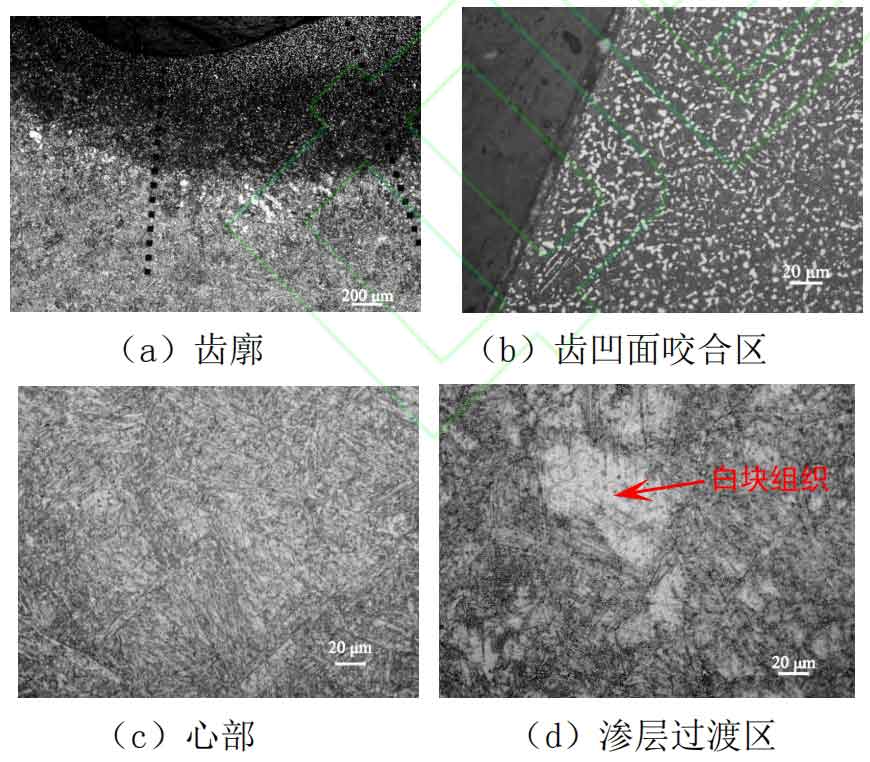
Cut one complete double tooth near the fracture surface of the faulty active arc gear for microscopic observation. The carbide level of the tooth profile infiltration layer is level 3, which meets the requirements of the standard (level 1-4). The morphology is shown in Figure 5 (a); The deformation characteristics can be observed on the surface of the concave meshing area, and the morphology is shown in Figure 5 (b); The core structure consists of tempered martensite and a small amount of residual austenite, with no abnormalities observed. The morphology is shown in Figure 5 (c); There is a white block like structure at the junction of the infiltration layer and the matrix, as shown in Figure 5 (d). The microhardness tests at this location showed hardness of 450, 507, and 445, which is significantly lower than the core hardness of 552.6, indicating that the white block like structure is residual austenite.
1.4 Hardness testing
The hardness test was conducted on the concave surface of the faulty active spiral bevel gear, and the results showed that the tooth surface HRC was 63.1, 63.4, and 63.2 (drawing requirements: HRC=60-67); Heart HRC=50.1, 51.5, 51.4 (drawing requirements: HRC=48-52).
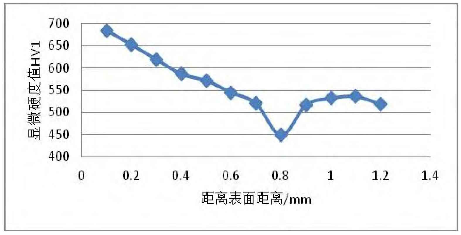
A single point microhardness test was conducted on the tooth and fillet penetration layer area of the faulty active spiral bevel gear, and the results are shown in Figure 6. From the figure, it can be seen that there is a soft spot band in the transition zone between the infiltrated layer and the core tissue of the faulty active bevel gear, and there is a white block like tissue at the corresponding position (as shown in Figure 5 (a) and (b)).
1.5 Component analysis
The energy spectrum analysis results of the faulty spiral bevel gear matrix are shown in Table 1, and there is no significant abnormality in the mass fraction of the main alloy elements.
| Elements | V | Cr | Co | Fe | Ni | Mo |
| Quality Score | 0.6 | 13.1 | 13.0 | 66.7 | 2.0 | 4.5 |
1.6 Simulation analysis and verification of meshing marks
In the technical requirements of spiral bevel gears, there are two types of contact marks on the gear pair: static contact marks and dynamic contact marks. Static contact marks are rolling contact marks obtained on the working surface of the gear after the installed gear pair is operated under slight braking of the rolling inspection machine. After loading, the dynamic contact imprint extends beyond the original static contact imprint within the elastic range of the gear material. Design requirements for colored bite marks on faulty spiral bevel gears: always an uninterrupted ellipse, always within the range of the tooth surface, without edge contact; The inspection positions include the theoretical meshing installation position and 8 inspection position points, totaling 9 positions. Among them, the theoretical meshing installation position imprint inspection adjusts the paired spiral bevel gears to the theoretical meshing installation position (i.e. the position where the top of the large/small gear cone coincides); The main basis for setting the 8 inspection position points is to consider the changes in the working position of the spiral bevel gear due to factors such as deformation and changes in bearing clearance under the axial force of the engine rotor.

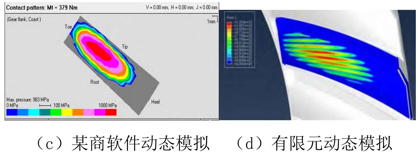
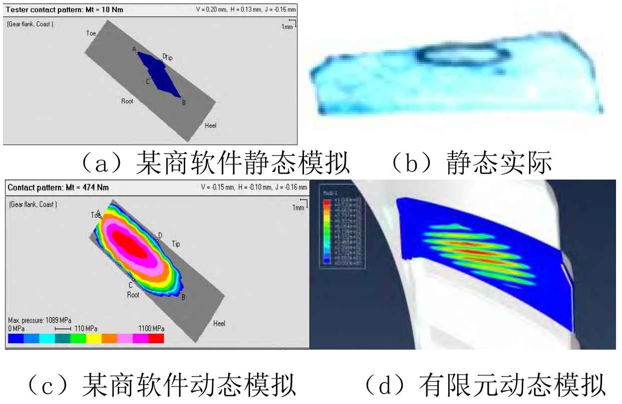
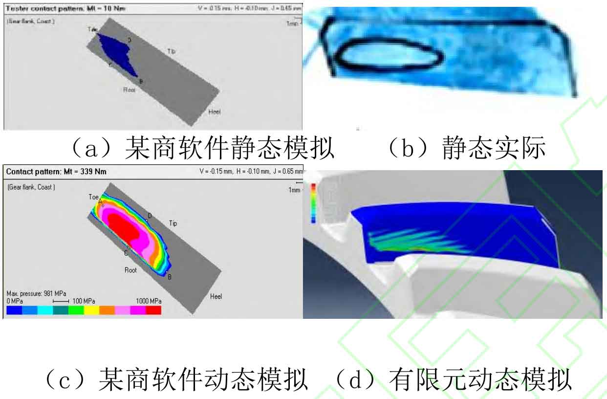
According to the inspection requirements after grinding teeth according to the coloring manual, a certain commercial software and finite element software were used to simulate and analyze the contact marks on the tooth surface, and a dedicated spiral bevel gear rolling inspection machine was used to verify the actual marks. The analysis and verification results are shown in Figures 7-9. The results show that the static contact marks on the tooth surface analyzed by a certain commercial software are basically consistent with the rolling inspection results of the actual processed parts. In some inspection positions, the tooth surface marks are very close to the edge of the gear teeth, and it is easy to occur tooth edge contact after applying working load; The contact imprints on the tooth surface of the two software simulation analyses are basically consistent. The tooth surface imprints of the active spiral bevel gear at theoretical position and position 1 are far from the tooth edge, and the contact stress is about 1100 MPa; The tooth surface imprint of the active spiral bevel gear at position 8 is very close to the tooth edge, and there is tooth edge contact, resulting in a significant increase in contact stress, reaching 1600-2000 MPa.
2. Analysis and discussion
From the inspection of the fracture surface of the faulty active spiral bevel gear, it can be seen that the crack in the faulty spiral bevel gear starts at the corner of the small end face and the root of the tooth convex surface, with a point source feature. Firstly, it extends from the small end face to the large end face, and then along both the axial and radial directions. After reaching the junction of the spoke plate, it extends circumferentially in the direction of rotation. After passing through four teeth, it cracks and falls off along the radial overload, and the expansion zone accounts for about 80% of the entire fracture surface area, with sufficient fatigue expansion; At the microscopic level, there are extensive tearing edges and fine fatigue band morphology features in the expansion zone. Combined with the judgment basis of high cycle fatigue fracture surface, it indicates that the failure nature of the crack in the active spiral bevel gear is high cycle fatigue.
Through macroscopic inspection of the faulty spiral bevel gear, it can be seen that the contact marks on the entire circumference of the driving spiral bevel gear are uneven, leaning towards the small end side and close to the tooth bottom; The contact marks on the driven spiral bevel gear are distributed at the small tooth tip, and the marks are incomplete and partially exceed the working surface, indicating that edge contact occurred during the working process of the faulty spiral bevel gear pair.
The shape, size, and position of the contact area on the tooth surface of spiral bevel gears have a direct impact on the smooth operation, load distribution, service life, and noise of the gears. Contact marks are an important indicator of the meshing quality of spiral bevel gears, and they are also the most critical issue in the development process of bevel gears. A certain company was the first to propose a parameter formation technology for spiral bevel gear machining based on the local conjugate principle, and used Tooth Contact Analysis (TCA) technology to simulate the meshing process of spiral bevel gears to obtain tooth surface contact marks and transmission error curves, thereby predicting the rationality of the obtained spiral bevel gear machining parameters. Calculate the geometric and machining parameters of the active spiral bevel gear, and select one reference point on the large gear tooth surface; Using the principle of local conjugation, find a point on the driven spiral bevel gear that is conjugate with the reference point of the driving wheel, calculate the normal curvature and normal vector of this point, and obtain the machining parameters of the driven spiral bevel gear. In actual production and processing, based on the results of rolling inspection tests, it is often necessary to repeatedly adjust the parameters to obtain a suitable contact mark and good meshing performance. From this, it can be seen that the colored bite marks on spiral bevel gears are closely related to the adjustment of machining parameters. According to the simulation and verification of bite marks at typical inspection positions on the working surface of faulty active spiral bevel gears, it can be concluded that for gears processed according to the detailed design parameters of existing bevel gear tooth surfaces, some static marks at typical inspection positions are located at the edge of the tooth profile; During the working process, under the action of load, the dynamic imprint on the concave surface of the active spiral bevel gear moves towards the small end and tooth root direction, causing edge contact and increasing stress at the tooth root. Under the abnormal interlocking effect of cyclic reciprocating, fatigue cracks are initiated at the corner of the small end face and the root of the tooth convex surface. Insufficient consideration of machining parameters on the tooth surface of spiral bevel gears is the main reason for the failure. Therefore, optimizing tooth surface machining parameters, simulating bite marks, and conducting experimental verification are the main measures to ensure that the trial production of spiral bevel gears fully meets the design requirements of colored bite marks, and to improve the bite quality during the working process of spiral bevel gears, which is to avoid such faults from occurring.
Based on the metallographic structure and microhardness testing of the faulty active spiral bevel gear, it is shown that there is a “soft spot” band (about 0.8 mm away from the surface) in the transition zone between the infiltrated layer structure and the core structure, and residual austenite structure exists at the corresponding position. The reason for this phenomenon should be due to the abundance of alloying elements and difficulty in carburizing in the 15Cr14Co12Mo5Ni2 material of the active bevel gear. If the carbon potential is too high and the diffusion time is insufficient during the long-term carburizing process, it is easy to cause the carbon and alloying elements of the material to aggregate in the carburizing transition zone, resulting in residual austenite bands (white block like structures) and the appearance of hardness soft spots. Therefore, reducing the stability of austenite during the cooling process through carburization process, parameter control and adjustment is the most effective way to eliminate and reduce residual austenite in the carburized layer of 15Cr14Co12Mo5Ni2. The crack of the active spiral bevel gear in this fault started from the edge surface of the small end face and the root of the tooth convex surface. No obvious residual austenite or other structural defects were found in the source area. The composition, structure, hardness and other aspects of the matrix material meet the standard requirements, indicating that it is not significantly related to the initiation of fatigue cracks in the spiral bevel gear.
3. Conclusion
(1) The fracture of the faulty active spiral bevel gear is characterized by high cycle fatigue and is not related to material or metallurgical defects;
(2) Insufficient consideration of machining parameters on the tooth surface of spiral bevel gears leads to abnormal engagement and increased stress at the tooth root during operation, which is the main cause of fatigue fracture of spiral bevel gears.
It is recommended to optimize tooth surface machining parameters, simulate bite marks, and conduct experimental verification to ensure that the spiral bevel gear fully meets the design requirements of colored bite marks after trial production, and to avoid abnormal bite during the working process of the spiral bevel gear.

