
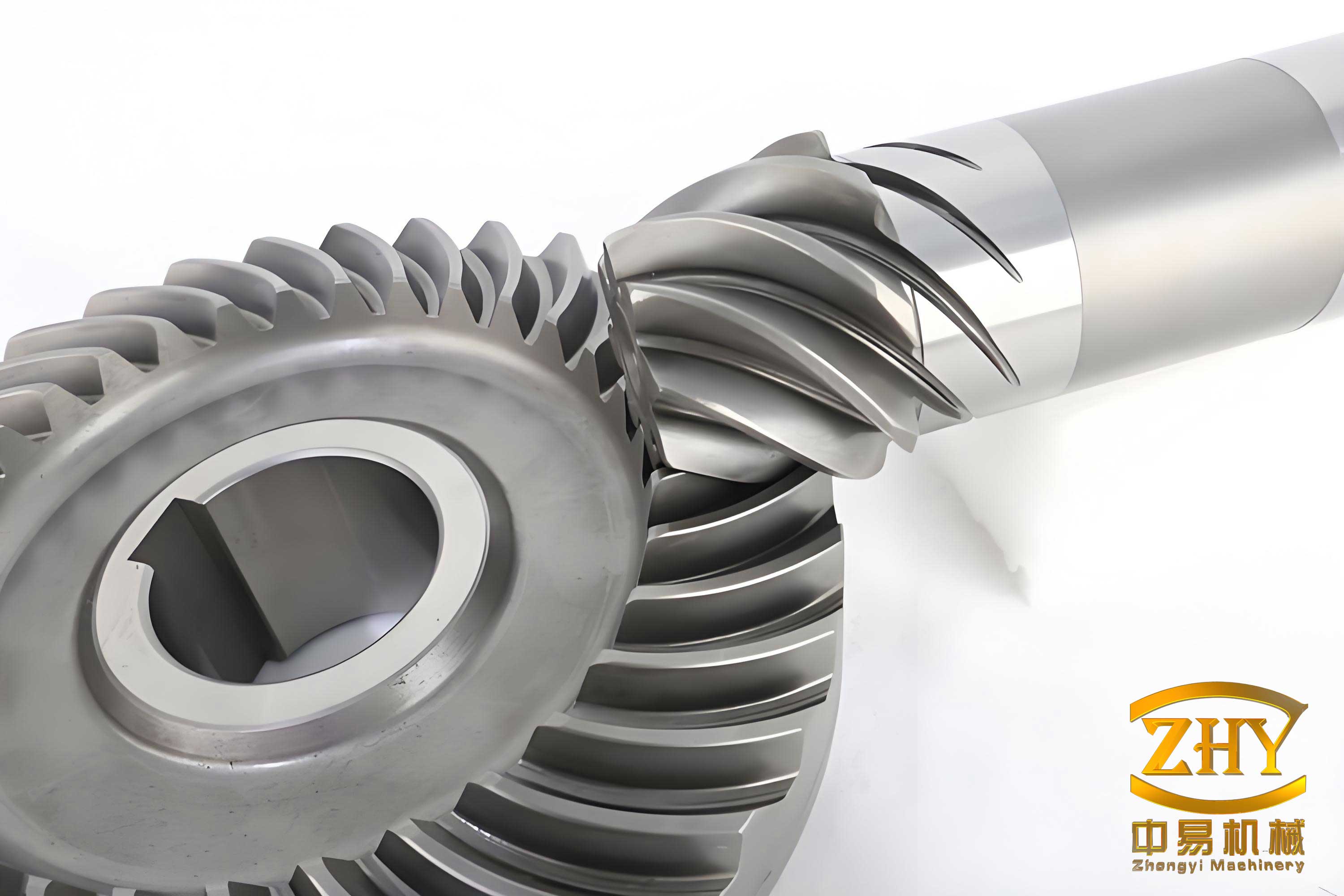
The transmission of power and motion through geared systems remains a cornerstone of mechanical engineering. Among the various gear types, spiral bevel gears hold a distinguished position for applications requiring high-power transmission between intersecting shafts, typically at a 90-degree angle. Their defining characteristic is the curved, oblique teeth which engage gradually compared to straight bevel gears. This results in smoother operation, higher contact ratios, reduced noise and vibration, and significantly greater load-carrying capacity. These advantages make spiral bevel gears the preferred choice in demanding sectors such as aerospace, automotive differentials, heavy machinery, and industrial drilling equipment.
However, the very complexity that grants the spiral bevel gear its superior performance also makes it susceptible to specific failure modes. The primary types of gear failure, including tooth breakage, pitting, scuffing, and wear, often initiate at points of high stress concentration. For spiral bevel gears, tooth bending fatigue failure at the fillet region of the root is a critical concern. During meshing, the tooth acts as a cantilever beam subjected to cyclic bending stresses. The root area experiences the highest bending moment coupled with a geometric stress concentration, making it the most likely site for crack initiation and propagation, ultimately leading to tooth fracture.
Traditional gear design and verification rely heavily on standardized calculation methods, such as those outlined by AGMA (American Gear Manufacturers Association) or ISO standards. These analytical methods provide valuable, conservative estimates for stress and safety factors. Nevertheless, they often involve significant simplifications regarding load distribution, exact tooth geometry (especially the critical root fillet), and boundary conditions. In contrast, Finite Element Analysis (FEA) offers a powerful computational tool to model the physical behavior of a spiral bevel gear under load with remarkable fidelity. By discretizing the complex gear geometry into a mesh of finite elements, FEA can solve the governing equations of elasticity numerically, providing a detailed visualization of stress, strain, and displacement fields that analytical formulas cannot easily capture.
This article details a comprehensive engineering workflow for the design and verification of a spiral bevel gear using Siemens UG NX software. The process integrates parametric modeling, advanced simulation, and result validation, demonstrating how modern CAD/CAE tools can streamline development, enhance reliability, and reduce costs for critical power transmission components like the spiral bevel gear.
1. Application Context: The Drilling Rig Gearbox
The spiral bevel gear under analysis is a critical component within the transmission system of a multi-purpose anchor drilling rig. This rig is designed for various geotechnical and construction applications, including anchor drilling, grouting, and core sampling. Its functionality demands a robust and reliable gearbox capable of transmitting high torque across multiple speed ranges. The primary function of the targeted spiral bevel gear pair is to redirect power flow by 90 degrees within the rotary head and transfer case, facilitating the final drive to the drilling tool.
The operational requirements are stringent. The gear must endure significant and fluctuating loads encountered during drilling into diverse geological formations. Performance is quantified by the torque output required at different gear stages. The design must ensure that the spiral bevel gear operates without failure under the maximum anticipated service loads. The rated design torque for the pinion (smaller spiral bevel gear) in this study is 2052.8 Nm. Table 1 summarizes the minimum required torque output for the drilling rig across its operational gear range, with the spiral bevel gear assembly being integral to achieving these performance metrics.
| Gear Stage | 1 | 2 | 3 | 4 | 5 | 6 | 7 | 8 |
|---|---|---|---|---|---|---|---|---|
| Torque (N·m) | 2627.6 | 1528.7 | 996.4 | 697.7 | 530.5 | 305.7 | 193.3 | 140.1 |
2. Parametric 3D Modeling of the Spiral Bevel Gear in UG NX
An accurate 3D geometric model is the foundational step for any meaningful finite element analysis. Manually modeling the complex, doubly-curved surface of a spiral bevel gear tooth is a time-consuming and error-prone process. UG NX software provides a significant advantage through its dedicated Gear Engineering tools, which automate the creation of standardized gear geometries.
For this study, the pinion of the spiral bevel gear pair was modeled. The gear generation module within UG NX requires a set of fundamental design parameters. These parameters, derived from the gear design calculations, fully define the geometry of the spiral bevel gear. The key input parameters for the subject spiral bevel gear are listed below:
- Module (m): 6 mm
- Number of Teeth (z): 25
- Pressure Angle (α): 20°
- Shaft Angle (Σ): 90°
- Spiral Angle (β): 35°
- Hand of Spiral: Left/Right (as per mating requirement)
- Face Width: Specified based on design layout.
By inputting these parameters into the gear toolbox, UG NX automatically generates a precise, watertight solid model of the spiral bevel gear. This parametric approach offers immense benefits:
- Rapid Prototyping: Design iterations (e.g., changing the number of teeth or module) can be executed in seconds.
- Accuracy: Eliminates human error inherent in manual sketching and sweeping operations.
- Integration: The model is native to the UG NX environment, ensuring seamless transition to the subsequent FEA and CAM modules.
This method revolutionizes the design cycle for complex components like the spiral bevel gear, shifting the engineer’s focus from laborious geometry creation to performance optimization and validation.
3. Theoretical Foundation for Bending Stress Analysis
Before proceeding to the finite element analysis, it is instructive to review the classical theory for calculating bending stress at the root of a gear tooth. The Lewis bending equation, though originally for spur gears, provides the conceptual basis. The nominal bending stress at the tooth root can be approximated by considering the tooth as a cantilever beam:
$$ \sigma_b = \frac{F_t}{b m_n} \cdot \frac{1}{Y_F} $$
Where:
$ \sigma_b $ = Bending stress at the tooth root
$ F_t $ = Tangential force component at the reference circle
$ b $ = Face width of the gear tooth
$ m_n $ = Normal module
$ Y_F $ = Form factor (a dimensionless parameter that accounts for tooth geometry, load application point, and stress concentration)
For spiral bevel gears, the calculation is more complex due to the oblique angle of the teeth. The force components must be resolved, and the virtual number of teeth (based on the formative gear in the normal plane) is used. The tangential force $ F_t $ is derived from the transmitted torque $ T $ and the pitch circle radius $ r_m $ at the mean cone distance:
$$ F_t = \frac{T}{r_m} $$
In this specific case, with a design torque $ T = 2052.8 \, \text{Nm} $, the tangential force is a primary input for the FEA. The AGMA standard provides a comprehensive methodology for spiral bevel gear rating, where the bending stress $ \sigma $ is calculated as:
$$ \sigma = \frac{F_t}{b m_t} \cdot \frac{K_a K_v K_m}{K_x} \cdot \frac{1}{Y_J} $$
Where:
$ m_t $ = Transverse module
$ K_a $ = Application factor
$ K_v $ = Dynamic factor
$ K_m $ = Load distribution factor
$ K_x $ = Size factor
$ Y_J $ = Geometry factor for bending strength (replacing $ Y_F $ and incorporating spiral bevel gear geometry).
The allowable bending stress $ \sigma_{FP} $ (fatigue limit) is determined from the material properties with adjustments for life, reliability, and temperature. The design is considered safe if:
$$ \sigma \leq \sigma_{FP} $$
The goal of the subsequent FEA is to compute a high-fidelity stress distribution, particularly the maximum von Mises stress at the root, and compare it to the material’s fatigue limit, providing a direct validation that complements the analytical approach.
4. Finite Element Analysis Workflow for the Spiral Bevel Gear
UG NX Advanced Simulation provides a fully integrated FEA environment. The workflow is structured into three main phases: Pre-processing, Solution, and Post-processing.
4.1 Pre-processing: Defining the Physics of the Model
This phase involves preparing the geometric model for analysis by assigning material properties, applying constraints and loads, and generating the computational mesh.
4.1.1 Material Properties
The spiral bevel gear is manufactured from 20CrMnTi, a case-hardening chromium-manganese-titanium alloy steel commonly used for high-strength gears. Its core provides good toughness, while the hardened surface offers excellent wear resistance. The UG NX material library contains closely comparable standard alloys. For this simulation, AISI 4340 steel was selected as a proxy due to its similar high-strength, quenched and tempered characteristics. The key material properties assigned to the spiral bevel gear model are summarized in Table 2.
| Property | Value | Units |
|---|---|---|
| Mass Density (ρ) | 7.85e-09 | Mg/mm³ (Tonnes/mm³) |
| Young’s Modulus (E) | 2.03e+05 | MPa (N/mm²) |
| Poisson’s Ratio (ν) | 0.29 | – |
| Yield Strength (σ_y) | 1178 | MPa |
| Ultimate Tensile Strength (σ_u) | 1240 | MPa |
4.1.2 Meshing
Meshing subdivides the continuous geometry of the spiral bevel gear into a finite number of discrete, simple-shaped elements (like tetrahedra or hexahedra). The accuracy of the FEA solution is heavily dependent on mesh quality and density, especially in regions of high-stress gradient. Given the complex curvature of the spiral bevel gear teeth, an automatic 3D tetrahedral mesh was employed. A 10-node quadratic tetrahedron (Tet 10) element type was chosen. These second-order elements can model curved geometries more accurately and provide better stress results than their first-order (4-node) counterparts.
A critical step was applying local mesh refinement at the tooth root fillets and the contact regions on the tooth flank. This ensures that the stress concentration, which is the focus of the analysis, is captured with sufficient resolution. The global element size was controlled to balance solution accuracy with computational efficiency. The final mesh for the spiral bevel gear consisted of several hundred thousand elements, providing a detailed discretization of the entire volume.
4.1.3 Boundary Conditions and Loads
Realistic boundary conditions are essential for a meaningful simulation. The analysis assumes a static load condition representing the peak torque scenario.
- Fixed Constraint: The inner splined bore of the spiral bevel gear, which mounts onto the shaft, was defined as a fixed constraint. This restricts all translational and rotational degrees of freedom, simulating the gear’s connection to a rigid shaft.
- Load Application: Applying the load correctly is crucial. Rather than applying a point load, which is unrealistic, a distributed force was applied normal to the tooth flank. The location of this force corresponds to the highest point of single tooth contact (HPSTC), which is the most critical loading position for bending stress. The magnitude of the resultant force vector was calculated from the design torque.
The pitch circle radius $ r_m $ at the mean cone distance for the spiral bevel gear pinion was calculated from its geometry. The tangential force component $ F_t $ is:
$$ F_t = \frac{T}{r_m} = \frac{2052.8 \, \text{Nm}}{0.075 \, \text{m}} \approx 27370 \, \text{N} $$
This tangential force, along with its radial and axial components determined by the pressure and spiral angles, defines the total contact force vector applied to the tooth surface. This represents the worst-case loading condition for the spiral bevel gear tooth.
4.2 Solution
With the pre-processing complete, the finite element model was solved using the NX Nastran solver integrated into UG NX. A linear static analysis (SOL 101) was performed. This type of analysis assumes:
- Material behavior is linear elastic (obeys Hooke’s Law).
- Displacements and strains are small.
- The applied load is static and does not change with time.
These assumptions are valid for assessing the stress state under a single, maximum load event for a ductile metal like the spiral bevel gear material. The solver computes the nodal displacements and, from these, derives the strains and stresses for every element in the mesh.
4.3 Post-processing: Interpreting the Results
Post-processing tools transform the vast numerical output from the solver into comprehensible visual and quantitative results. For the spiral bevel gear analysis, the primary outputs of interest were the displacement field and the stress field.
4.3.1 Displacement Plot
The displacement magnitude plot shows the exaggerated deformation of the spiral bevel gear under the applied load. It visually confirms that the maximum deflection occurs at the tip of the loaded tooth, behaving like a bending cantilever. The fixed constraint at the bore is clearly effective, showing minimal to zero displacement. This plot serves as a quick sanity check on the applied boundary conditions.
4.3.2 Von Mises Stress Plot
The von Mises stress criterion is the most widely used metric for predicting yield initiation in ductile metals under complex multiaxial stress states. It is an equivalent tensile stress calculated from the principal stresses. The contour plot of von Mises stress across the spiral bevel gear is the most critical result.
The plot vividly reveals the stress concentration at the root fillet on the loaded side of the tooth. The stress gradient is very high in this region. The maximum von Mises stress value, as extracted from the FEA solver, was found to be:
$$ \sigma_{vM}^{max} = 211.1 \, \text{MPa} $$
This maximum stress is located precisely at the root fillet, aligning perfectly with theoretical expectations for bending failure in a spiral bevel gear. The remainder of the gear body, including the web and rim, shows significantly lower stress levels, confirming that the tooth root is the critical section.
5. Validation and Discussion of Results
The final step is to validate the FEA result against the material’s capability. The fatigue bending limit for the 20CrMnTi spiral bevel gear material, after considering appropriate life factors, surface finish, and reliability requirements, was calculated using standard gear design practices. This allowable stress $ \sigma_{FP} $ was determined to be approximately 206.8 MPa.
We can now compare the computed maximum stress from the FEA with this allowable limit:
FEA Maximum Stress: $ \sigma_{vM}^{max} = 211.1 \, \text{MPa} $
Material Allowable Stress: $ \sigma_{FP} = 206.8 \, \text{MPa} $
The FEA result shows a close correlation with the analytically derived fatigue limit. The calculated stress is marginally higher (~2%) than the allowable limit. In an engineering design context, this is often considered acceptable, especially when considering the following factors:
- Conservative Assumptions: The analysis used the peak design torque and the worst-case load position (HPSTC). In service, the average load is often lower, and the load is shared across multiple teeth due to the high contact ratio of the spiral bevel gear.
- Material Strength: The material properties used in the analytical limit are minimum guaranteed values. Actual material batches often exhibit higher strength.
- Safety Factor Margin: A small exceedance in a linear static analysis does not imply immediate failure; it indicates a slightly lower design factor. For robust applications, a minimum safety factor (e.g., $ S_F = \sigma_{FP} / \sigma_{vM}^{max} $) of 1.1 to 1.5 is often targeted. Here, $ S_F \approx 0.98 $. A minor design adjustment, such as a slight increase in fillet radius or a small increase in face width, could easily bring this factor above 1.0.
Therefore, the conclusion is that the spiral bevel gear design is fundamentally sound and very close to the optimal balance between weight, size, and strength. The FEA has successfully identified the critical area and quantified the stress level with high precision.
| Parameter | Symbol | Value | Unit | Notes |
|---|---|---|---|---|
| Design Torque | T | 2052.8 | Nm | Input |
| Calculated Tangential Force | F_t | ~27370 | N | Derived from T and r_m |
| Max. von Mises Stress (FEA) | σ_vM^max | 211.1 | MPa | From UG NX solution |
| Material Allowable Stress | σ_FP | 206.8 | MPa | Based on 20CrMnTi properties |
| Calculated Safety Factor | S_F | ~0.98 | – | σ_FP / σ_vM^max |
| Assessment | Design is borderline acceptable. A minor geometric optimization (e.g., increased root fillet) is recommended to raise S_F > 1.1. | |||
6. Advantages of the Integrated UG NX CAD/CAE Approach
This case study highlights the transformative impact of an integrated software environment like UG NX on the design process for complex mechanical components such as the spiral bevel gear. The key advantages are:
- Streamlined Workflow and Reduced Cycle Time: The seamless transition from parametric modeling in the Gear Toolbox to advanced simulation within the same software eliminates time-consuming data translation, file export/import, and geometry repair that plague disjointed CAD and CAE tools. Changes to the spiral bevel gear geometry can be updated in the model, and the FEA setup (mesh, loads, constraints) is often associative, automatically updating to reflect the new design.
- Enhanced Accuracy and Insight: FEA provides a level of detail unattainable by hand calculations. The visual stress contour plots allow engineers to identify not just the maximum stress value, but also the complete stress distribution across the spiral bevel gear tooth and body. This can reveal unexpected stress concentrations in non-tooth areas (e.g., web-to-rim junctions) that traditional methods might overlook.
- Cost and Risk Reduction: Virtual prototyping and testing via FEA significantly reduce the need for physical prototypes. Potential failure modes in the spiral bevel gear are identified and addressed digitally before any metal is cut. This prevents costly design revisions late in the production cycle and mitigates the risk of field failures.
- Design Optimization: The process facilitates optimization. Engineers can now easily run “what-if” scenarios: What if the face width of the spiral bevel gear is increased by 5%? What if a larger root fillet is used? The impact on stress and weight can be quantified rapidly, leading to an optimized design that is both lightweight and strong.
7. Conclusion
The successful modeling and finite element analysis of a spiral bevel gear for a heavy-duty drilling rig demonstrates the power of modern engineering software. Utilizing UG NX’s integrated tools, a parametric model of the spiral bevel gear was generated efficiently, and a detailed static structural analysis was performed. The results clearly identified the tooth root as the critical region for bending stress, with a maximum von Mises stress of 211.1 MPa. This value showed close agreement with the analytically determined bending fatigue limit of the material (206.8 MPa), validating the core design while indicating a minor area for potential improvement.
This workflow underscores a fundamental shift in mechanical design. The integration of CAD, CAE, and CAM transforms a sequential, trial-and-error process into a concurrent, simulation-driven engineering practice. For power transmission components as critical as the spiral bevel gear, this approach is no longer a luxury but a necessity. It empowers engineers to deliver more reliable, optimized, and cost-effective products by virtually eliminating design flaws before manufacturing begins, thereby ensuring the durability and performance of the entire mechanical system in which the spiral bevel gear operates.