
In my work on precision manufacturing, I have repeatedly seen that the final quality of a gear transmission is not determined only by design or by the upstream gear cutting operation. It is determined by the entire chain of operations, and among those operations, precision grinding often acts as the last and most influential barrier against geometric error. A gear that has been cut, heat treated, and prepared for service can still fail to meet transmission requirements if grinding introduces profile deviation, pitch deviation, lead deviation, surface roughness, or thermal damage. For this reason, I examine precision gear grinding not as an isolated finishing step but as a system of machine, tool, process, material, thermal, and measurement interactions. My goal in this discussion is to organize the main error sources, present quantitative relationships that I use to reason about them, and propose control methods that can be applied in production. I also include a case-based evaluation to show how systematic error control improves gear cutting quality and final product stability.
In my experience, gear cutting and gear grinding are complementary. Gear cutting creates the initial tooth space, establishes the basic geometry, and determines how much stock must be removed by grinding. If gear cutting is unstable, the grinding allowance becomes uneven, and the grinding wheel must remove different amounts of material around the gear. That variation changes grinding force, temperature, wheel wear, and elastic deflection. The result is a gear with inconsistent profile and pitch characteristics. Therefore, when I analyze grinding error, I also inspect the preceding gear cutting process, the heat treatment distortion, and the fixture conditions. Error control is never only a matter of selecting a finer grinding wheel or lowering the feed rate. It is a matter of controlling the complete manufacturing system.
I model the total grinding error as a superposition of several contributions:
$$E_{total} = E_{machine} + E_{fixture} + E_{process} + E_{material} + E_{thermal} + E_{measurement} + E_{random}$$
Here, \(E_{machine}\) represents geometric and dynamic errors from the machine tool, \(E_{fixture}\) represents locating and clamping errors, \(E_{process}\) represents errors caused by grinding parameters and wheel conditions, \(E_{material}\) represents errors related to material hardness and uniformity, \(E_{thermal}\) represents thermal deformation and thermal damage, \(E_{measurement}\) represents inspection uncertainty, and \(E_{random}\) represents unpredictable disturbances. I do not treat these terms as perfectly independent, because in real production they interact. For example, thermal deformation can change the effective depth of cut, which then changes grinding force and wheel wear. That interaction can amplify profile error. My control strategy therefore focuses on reducing the dominant terms and breaking the feedback loops that allow small errors to become large errors.
My View of Precision Gear Grinding Error Formation
When I inspect a ground gear that does not meet specification, I separate the error into four main geometric categories: profile error, pitch error, lead error, and surface integrity error. Profile error describes the deviation of the actual tooth flank from the theoretical involute. Pitch error describes the deviation between adjacent tooth positions or the cumulative position around the gear. Lead error describes the deviation along the tooth width direction. Surface integrity error includes roughness, burning, microcracks, residual stress, and hardness change. Each category has different root causes, but they often share common sources such as machine stiffness, thermal growth, wheel imbalance, fixture error, and inappropriate grinding parameters.
I use the following general representation for a measured profile deviation:
$$f_{\alpha} = \max \left( y_{actual}(\alpha) – y_{theoretical}(\alpha) \right) – \min \left( y_{actual}(\alpha) – y_{theoretical}(\alpha) \right)$$
where \(\alpha\) is the roll angle along the involute and \(y\) is the normal deviation. For pitch deviation, I use:
$$f_{pt} = p_{actual} – p_{theoretical}$$
For cumulative pitch deviation, I use:
$$F_p = \max(p_i) – \min(p_i)$$
For lead deviation, I use:
$$F_{\beta} = \max(z_i) – \min(z_i)$$
These quantities are not just inspection numbers. In my analysis, they are signatures of the manufacturing process. A periodic pitch error often points to fixture indexing error, spindle error, or wheel eccentricity. A gradual lead error often points to guideway straightness error, thermal tilt, or table motion error. A profile error that changes from tooth to tooth often points to uneven grinding allowance from gear cutting or heat treatment distortion. When I see surface roughness variation around the gear, I look for wheel loading, coolant distribution problems, or uneven contact caused by misalignment.
I also consider that gear cutting quality directly affects the grinding allowance distribution. If the gear cutting process leaves a large eccentric error, the grinding wheel will remove more material on one side than the other. The varying depth of cut produces varying force:
$$F_t = K_c A_c$$
where \(F_t\) is the tangential grinding force, \(K_c\) is the specific cutting energy, and \(A_c\) is the instantaneous chip cross-sectional area. When \(A_c\) varies, \(F_t\) varies, and the machine, fixture, wheel, and workpiece deflect differently. This deflection is then copied into the final tooth flank. I therefore treat gear cutting consistency as a prerequisite for precision grinding. A stable gear cutting process reduces the grinding stock variation and makes the grinding process more predictable.
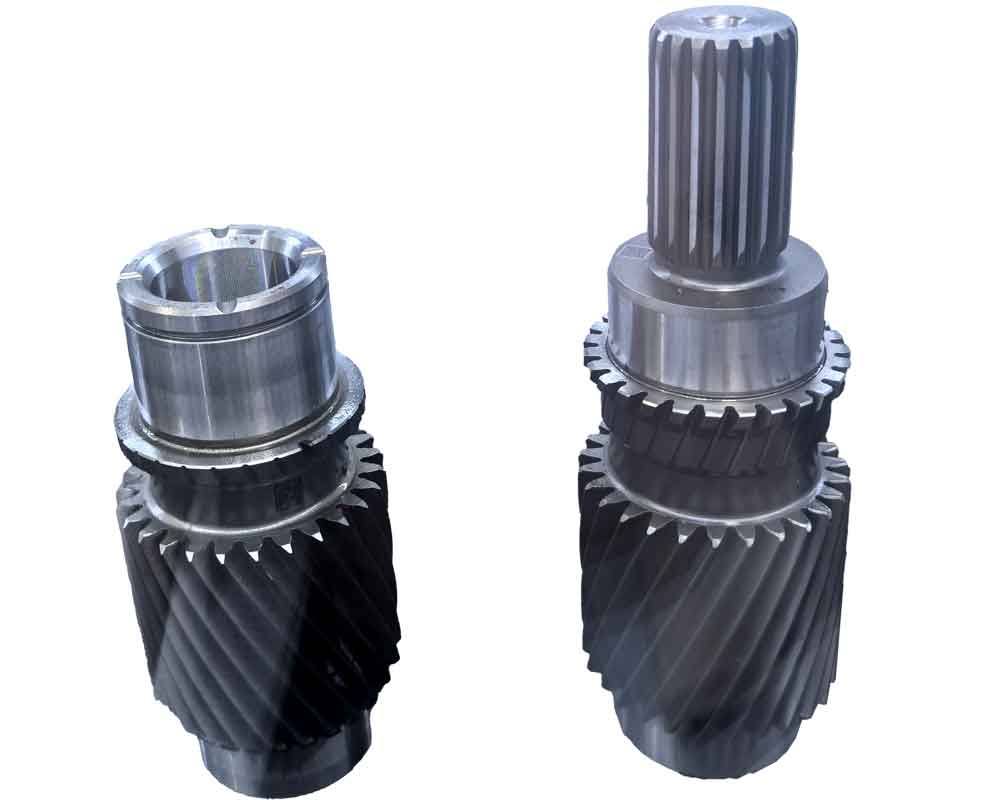
Machine Tool Factors That I Evaluate
In my assessment, the machine tool is the foundation of grinding accuracy. A precision gear grinding machine must have high static stiffness, high dynamic stiffness, good damping, low thermal drift, and accurate motion control. Static stiffness determines how much the machine deflects under grinding force. I express stiffness as:
$$K = \frac{F}{\delta}$$
where \(K\) is stiffness, \(F\) is the applied force, and \(\delta\) is the resulting deflection. If the machine stiffness is low, even a moderate grinding force produces a significant relative displacement between the wheel and the workpiece. That displacement changes the effective depth of cut and creates profile error. In my experience, the most critical stiffness paths are the wheel spindle, the work spindle, the tailstock, the carriage, the guideways, and the fixture interface. A weak point anywhere in that loop can dominate the total error.
Dynamic stiffness is equally important because grinding is a cutting process with periodic excitation. The wheel rotation, the workpiece rotation, the motion of the dresser, and the discrete engagement of abrasive grains all generate vibration. If the excitation frequency approaches a natural frequency of the machine or fixture, resonance can occur. I represent the dynamic compliance as:
$$H(\omega) = \frac{1}{K – m\omega^2 + j c\omega}$$
where \(m\) is the effective mass, \(c\) is the damping coefficient, and \(\omega\) is the excitation frequency. A high dynamic stiffness over the relevant frequency range reduces chatter and improves surface finish. In precision gear grinding, chatter is particularly harmful because it creates waviness on the tooth flank and can produce noise during operation. I have found that wheel balancing, spindle bearing preload, and fixture rigidity are among the most effective ways to improve dynamic behavior.
I also examine machine geometric accuracy. The following table summarizes the machine-related error sources that I check during process qualification.
| Machine element | Typical error effect | Inspection method I use | Control action I recommend |
|---|---|---|---|
| Wheel spindle | Runout, axial play, thermal growth | Dial indicator, capacitance probe, temperature logging | Bearing replacement, preload adjustment, warm-up cycle |
| Work spindle | Eccentricity, angular error, thermal drift | Test mandrel, encoder comparison, thermal mapping | Spindle calibration, cooling control, error compensation |
| Guideways | Straightness error, yaw, pitch, roll | Laser interferometer, autocollimator | Way reconditioning, preload, compensation table |
| CNC axes | Position error, following error, interpolation error | Ballbar, encoder feedback, servo trace | Gain tuning, backlash compensation, thermal compensation |
| Dresser | Profile error, wheel form error, wear | Dressing force monitoring, wheel profile measurement | Dresser replacement, dressing parameter optimization |
| Coolant system | Thermal variation, poor chip removal, wheel loading | Flow and pressure measurement, temperature logging | Nozzle redesign, filtration improvement, flow control |
In my view, machine tool accuracy is not a one-time purchase decision. It is a maintenance and control discipline. A machine that is accurate when new can lose accuracy after months of production because of wear, thermal drift, foundation settlement, or inadequate maintenance. I therefore recommend periodic calibration and trend monitoring. For example, I track spindle growth as a function of running time and ambient temperature. I then build a compensation model:
$$\Delta z_{comp} = a_0 + a_1 T + a_2 t + a_3 T t$$
where \(T\) is temperature, \(t\) is running time, and \(a_0, a_1, a_2, a_3\) are coefficients determined from data. Applying this compensation to the CNC axis reduces thermal error during long production runs. This is especially important for gear cutting and grinding lines that run continuously, because thermal drift accumulates and shifts the tooth flank position.
Fixture and Workholding Factors
I have often found that fixture error is underestimated in gear grinding. The workpiece must be located and clamped with high repeatability. If the locating surface is not clean, if the clamp force is uneven, or if the fixture stiffness is insufficient, the gear will move or deform during grinding. The result is pitch error, runout, and profile error. I evaluate fixture performance using the locating error model:
$$\delta_{loc} = \delta_{datum} + \delta_{fit} + \delta_{clamp} + \delta_{thermal}$$
where \(\delta_{datum}\) is datum surface error, \(\delta_{fit}\) is fit clearance error, \(\delta_{clamp}\) is clamping deformation, and \(\delta_{thermal}\) is thermal mismatch between fixture and workpiece. I reduce these errors by using precision arbors, hydrostatic or hydro-mechanical expansion fixtures, and controlled clamp pressure. For high-precision gears, I prefer fixtures that apply force uniformly around the bore or hub rather than point clamping. Point clamping can ovalize the gear and distort the tooth profile after grinding.
I also consider the effect of clamping on gear cutting and grinding. If the gear is clamped differently in gear cutting than in grinding, the residual stress and elastic deformation will be different, and the final ground tooth will not match the cut tooth. I therefore try to standardize the locating and clamping method across gear cutting, heat treatment, and grinding. This reduces the chance that a geometrically acceptable cut gear becomes a nonconforming ground gear.
Process Parameter Factors
Process parameters are the variables I can adjust most directly. The main parameters are wheel speed, workpiece speed, feed rate, depth of cut, coolant flow, and dressing conditions. Each parameter affects grinding force, temperature, wheel wear, and surface quality. I use the following relationships to guide my decisions.
The wheel circumferential speed is:
$$v_s = \frac{\pi d_s n_s}{60000}$$
where \(v_s\) is wheel speed in m/s, \(d_s\) is wheel diameter in mm, and \(n_s\) is wheel speed in rpm. The workpiece speed is:
$$v_w = \frac{\pi d_w n_w}{1000}$$
where \(v_w\) is workpiece speed in m/min, \(d_w\) is workpiece diameter in mm, and \(n_w\) is workpiece speed in rpm. The specific material removal rate in grinding is often expressed as:
$$Q’ = a_e v_w$$
where \(Q’\) is specific removal rate per unit width and \(a_e\) is the radial depth of cut. The equivalent chip thickness, which influences force and temperature, can be approximated as:
$$h_{eq} = \frac{v_w}{v_s} a_e$$
In my experience, increasing wheel speed usually reduces the chip thickness and can improve surface finish, but it also increases heat generation per unit time. The heat flux into the workpiece is approximately:
$$q_w = \eta F_t v_s$$
where \(\eta\) is the fraction of grinding energy entering the workpiece. If \(q_w\) is too high, the workpiece surface can burn, temper, or crack. If wheel speed is too low, the grinding force increases, and the wheel may glaze or load. Therefore, I optimize wheel speed together with depth of cut and feed rate rather than changing one parameter in isolation.
The following table summarizes the parameter effects I consider during process design.
| Parameter | Increase effect | Risk if too high | Risk if too low | My preferred control approach |
|---|---|---|---|---|
| Wheel speed | Lower chip thickness, better finish | Thermal damage, wheel burst risk | High force, wheel loading, poor finish | Use manufacturer range and thermal monitoring |
| Workpiece speed | Higher productivity, less thermal concentration | Vibration, profile error, poor finish | Low productivity, local burning | Match to wheel speed and wheel specification |
| Feed rate | Higher removal rate | Force increase, chatter, wheel wear | Low efficiency, wheel glazing | Use constant force or adaptive control |
| Depth of cut | Higher removal rate | Burn, deflection, profile error | Long cycle time, wheel rubbing | Use roughing and finishing passes |
| Coolant flow | Better cooling and chip removal | Pressure loss, mist, waste | Burning, loading, thermal error | Optimize nozzle position and flow rate |
| Dressing interval | Sharp wheel, stable cutting | Wheel consumption, profile loss | Loading, force increase, burn | Monitor force and surface quality |
I have also learned that process parameters must be matched to the gear geometry. A small module gear has different contact conditions than a large module gear. A helical gear introduces additional contact length and axial force. A gear with a narrow face width may require a different feed strategy than a wide gear. In gear cutting and grinding, I prefer to establish a parameter window for each gear family rather than use one universal setting. This prevents the common mistake of copying parameters from one part to another without considering the change in contact geometry.
Material and Heat Treatment Factors
Material behavior has a strong influence on grinding error. I consider hardness, hardenability, microstructure uniformity, inclusion content, and residual stress. If the material is too hard, grinding force increases, and the wheel wears rapidly. If the material is too soft, the wheel may load, and the surface may smear. If the hardness varies around the gear, the grinding force varies, and the final profile becomes inconsistent. I represent the effect of hardness variation on grinding force as:
$$F_t = F_{t0} + \frac{\partial F_t}{\partial H} \Delta H + \frac{\partial F_t}{\partial v_s} \Delta v_s + \frac{\partial F_t}{\partial a_e} \Delta a_e$$
where \(H\) is hardness. In my analysis, \(\Delta H\) is often caused by uneven heat treatment, poor quenching, or inadequate tempering. I therefore work with heat treatment engineers to ensure uniform case depth and core hardness. For carburized gears, I check case depth variation and surface oxidation. For through-hardened gears, I check hardness uniformity and residual stress. This is important because gear cutting and grinding both remove material and redistribute residual stress. If the stress distribution is not controlled, the gear can distort after grinding or during service.
I also evaluate the effect of material on thermal damage. The critical temperature for tempering or burning depends on the material and its prior heat treatment. I use the following approximate relation for the workpiece surface temperature rise:
$$\Delta T = \frac{q_w}{\sqrt{\pi k \rho c_p t_c}}$$
where \(k\) is thermal conductivity, \(\rho\) is density, \(c_p\) is specific heat, and \(t_c\) is contact time. If \(\Delta T\) exceeds the tempering temperature, the surface hardness drops. If it exceeds the austenitizing temperature, rehardening and cracks can occur. In my experience, material uniformity is one of the most effective ways to reduce grinding burn. A uniform microstructure allows the grinding process to be more predictable and reduces the need for overly conservative parameters.
Thermal Effects and Error Control
Thermal effects are among the most difficult error sources because they are time-dependent and distributed. Heat is generated at the grinding zone, conducted into the workpiece, wheel, chips, coolant, and machine structure. The resulting temperature field causes thermal expansion. I use the linear thermal expansion relation:
$$\Delta L = \alpha L \Delta T$$
where \(\alpha\) is the coefficient of thermal expansion, \(L\) is the original length, and \(\Delta T\) is the temperature change. For a gear grinding machine, the relevant lengths include the wheel spindle, work spindle, carriage, column, and fixture. Even a small temperature change can produce a significant displacement. For example, a 1 m steel structure with \(\alpha = 11 \times 10^{-6} / ^\circ C\) and \(\Delta T = 5 ^\circ C\) changes length by:
$$\Delta L = 11 \times 10^{-6} \times 1000 \times 5 = 0.055 \text{ mm}$$
In precision gear grinding, 0.055 mm is a large error. It can shift the tooth profile and pitch position beyond specification. I therefore treat thermal control as a first-order requirement. I use warm-up cycles, temperature-controlled coolant, thermal compensation models, and stable ambient conditions. I also group production runs so that the machine reaches a stable thermal state before precision grinding. If the machine is started and stopped repeatedly, the thermal state changes, and the first parts may differ from later parts.
The heat partition in grinding can be modeled as:
$$q_{total} = q_w + q_s + q_c + q_f + q_{environment}$$
where \(q_w\) is heat to workpiece, \(q_s\) is heat to wheel, \(q_c\) is heat to chips, \(q_f\) is heat to coolant, and \(q_{environment}\) is heat lost to surroundings. I try to maximize \(q_f\) through efficient coolant application because heat removed by coolant does not cause thermal damage or thermal growth. However, I also recognize that coolant cannot remove all heat. Some heat always enters the workpiece and machine. Therefore, I combine cooling with process parameter control and thermal compensation.
I have used the following thermal error compensation structure in several projects:
$$E_{thermal}(t) = \sum_{i=1}^{n} \beta_i \Delta T_i(t – \tau_i)$$
where \(\Delta T_i\) are measured temperature rises at critical points, \(\tau_i\) are time delays, and \(\beta_i\) are coefficients. I identify the coefficients from experiments and then apply the predicted error as an offset in the CNC. This approach works well when the thermal behavior is repeatable. When the behavior is not repeatable, I focus more on design changes such as improved cooling, symmetric structure, and low-expansion materials.
Measurement and Error Separation
I cannot control what I cannot measure. In precision gear grinding, measurement is part of the control loop. I use gear measurement machines, laser interferometers, roundness testers, surface roughness testers, and in-process sensors. I also use error separation techniques to distinguish machine error from workpiece error. For example, if I measure the same gear before and after grinding, I can estimate the stock removal distribution. If I measure a master gear on the machine, I can estimate machine geometric error. If I measure the wheel profile after dressing, I can estimate wheel form error.
I use the following relation for the measured profile error:
$$E_{measured} = E_{workpiece} + E_{machine} + E_{probe} + E_{environment}$$
By repeating measurements under different conditions, I can separate some of these terms. For example, I rotate the workpiece relative to the fixture and measure again. If the error pattern rotates with the workpiece, the error is likely on the workpiece. If the error pattern stays fixed relative to the machine, the error is likely in the machine or fixture. This distinction is important because it determines whether I should correct the grinding process, the fixture, or the machine.
| Measurement target | Instrument I use | Error signature | Control decision |
|---|---|---|---|
| Profile deviation | Gear measuring center | Involute form error, pressure angle error | Adjust wheel profile, dressing, or machine compensation |
| Pitch deviation | Gear measuring center, encoder | Single pitch and cumulative pitch error | Check work spindle, fixture indexing, and thermal drift |
| Lead deviation | Gear measuring center, laser interferometer | Helix slope and form error | Check guideway, carriage, and axial motion |
| Surface roughness | Profilometer, optical surface tester | Ra, Rz, waviness | Adjust wheel specification, dressing, and feed |
| Thermal drift | Thermocouples, displacement sensors | Time-dependent displacement | Apply thermal compensation and cooling control |
| Vibration | Accelerometers, spindle analyzer | Chatter frequency, amplitude | Balance wheel, adjust speed, stiffen fixture |
In my practice, measurement uncertainty must be smaller than the manufacturing tolerance. If the measurement system is not capable, the control loop becomes unreliable. I therefore calibrate instruments regularly, control temperature in the inspection room, and use appropriate fixtures for measurement. I also use the same datum strategy for measurement as for machining whenever possible. This reduces datum mismatch error and makes the measurement result more representative of the functional gear geometry.
Control Methods I Recommend
Based on the error sources above, I organize control methods into five groups: parameter optimization, tool selection and maintenance, machine accuracy improvement, thermal error control, and closed-loop compensation. I apply these groups together because no single method can eliminate all errors.
Optimizing Grinding Parameters
I optimize parameters by establishing a stable grinding window. I first define the acceptable ranges for wheel speed, workpiece speed, feed rate, and depth of cut. Then I run designed experiments to identify the combination that minimizes profile error, pitch error, and surface roughness while maintaining acceptable cycle time. I use the following objective function:
$$J = w_1 f_{\alpha} + w_2 F_p + w_3 R_a + w_4 t_c + w_5 B$$
where \(f_{\alpha}\) is profile error, \(F_p\) is cumulative pitch error, \(R_a\) is surface roughness, \(t_c\) is cycle time, \(B\) is a burn indicator, and \(w_i\) are weights. In my experience, the weights should reflect the functional requirements of the gear. For a high-speed transmission gear, pitch and profile errors may be more important than cycle time. For a general industrial gear, cycle time may have a higher weight. I do not use one universal objective function for all gear types.
I also use staged grinding. In rough grinding, I remove most of the stock with a relatively high material removal rate. In semi-finish grinding, I reduce the stock and improve geometry. In finish grinding, I use a small depth of cut and a sharp wheel to achieve the final profile and surface finish. This staged approach reduces thermal load and wheel wear. It also reduces the risk of a single deep pass causing deflection and profile error. I have found that staged grinding is especially effective for gears with large grinding allowance after heat treatment.
Selecting and Maintaining Grinding Tools
The grinding wheel is the cutting tool, and its condition directly affects gear cutting quality. I select abrasive type, grain size, grade, bond, and porosity according to the workpiece material and gear geometry. For hard gear steels, I often use cubic boron nitride or diamond wheels. For general applications, I use aluminum oxide or silicon carbide wheels with appropriate specifications. The wheel must be balanced, dressed, and mounted correctly. An unbalanced wheel creates vibration, which appears as waviness on the tooth flank. A glazed wheel increases force and temperature. A loaded wheel causes poor surface finish and profile error.
I monitor wheel wear using the grinding force ratio:
$$G = \frac{V_w}{V_s}$$
where \(G\) is the grinding ratio, \(V_w\) is the volume of workpiece material removed, and \(V_s\) is the volume of wheel wear. A high \(G\) means the wheel is wearing slowly, which is generally desirable for size control. A low \(G\) means rapid wear, which can cause profile drift. I also monitor spindle power, acoustic emission, and surface roughness. When spindle power rises or acoustic emission changes, I dress the wheel or replace it. I do not wait until the wheel is obviously worn, because the transition from stable to unstable grinding can be sudden.
| Wheel condition | Symptom I observe | Effect on gear error | Action I take |
|---|---|---|---|
| Glazing | High force, low material removal, shiny surface | Burn, profile error, poor roughness | Dress with sharp diamond, reduce wheel speed or increase depth |
| Loading | Pores filled with chips, high temperature | Surface smearing, roughness increase | Improve coolant, reduce feed, dress wheel |
| Excessive wear | Profile drift, size change | Lead and profile error | Replace wheel, adjust dressing interval |
| Imbalance | Vibration at spindle frequency | Waviness, chatter marks | Balance wheel, check mounting taper |
| Poor dressing | Dull grains, incorrect profile | Form error, pitch error | Optimize dressing speed, depth, and diamond condition |
Improving Machine Accuracy
I improve machine accuracy by selecting machines with high static and dynamic stiffness, low thermal drift, and accurate CNC control. I also maintain the machine carefully. This includes checking foundation bolts, guideway lubrication, ball screw preload, spindle bearing condition, and coolant system performance. I use laser calibration and ballbar testing to identify geometric and dynamic errors. I then apply compensation in the CNC. For example, if I measure a straightness error along the workpiece axis, I can add a position-dependent compensation table:
$$\Delta x(z) = c_0 + c_1 z + c_2 z^2 + c_3 z^3$$
where \(z\) is the axis position and \(c_i\) are coefficients fitted to the measured error. This compensation reduces lead error and improves tooth width consistency. Similarly, I can compensate for pitch error caused by work spindle encoder error or thermal growth. The key is to measure the error under conditions that represent production and to update the compensation periodically.
I also recommend in-situ measurement for high-value gears. In-situ measurement allows the machine to measure the gear before removing it from the fixture. If the measurement shows an error, the machine can apply a corrective pass. This reduces handling error and shortens the feedback loop. In my view, in-situ measurement is one of the most effective ways to control precision gear grinding error because it eliminates the uncertainty of re-fixturing.
Thermal Error Control
I control thermal error through design, operation, and compensation. From a design perspective, I prefer symmetric machine structures, low-expansion materials, and efficient cooling paths. From an operation perspective, I use warm-up cycles, stable ambient temperature, and controlled coolant temperature. From a compensation perspective, I use temperature sensors and predictive models. I also avoid long continuous grinding without interruption. Instead, I schedule short pauses or alternate operations to allow heat to dissipate. This reduces the accumulation of thermal error.
I use the following coolant control relation:
$$Q_{cool} = \dot{m} c_p (T_{out} – T_{in})$$
where \(Q_{cool}\) is the heat removed by coolant, \(\dot{m}\) is mass flow rate, \(c_p\) is specific heat, and \(T_{out} – T_{in}\) is the temperature rise of the coolant. To improve cooling, I can increase flow rate, reduce inlet temperature, or improve nozzle direction. However, I must also avoid excessive flow that causes turbulence, mist, or wheel deflection. I therefore optimize coolant application experimentally. I use high-pressure coolant through the grinding zone, and I position the nozzle close to the contact area. This improves heat removal and chip evacuation.
Closed-Loop Compensation
In my view, the future of precision gear grinding is closed-loop compensation. Instead of relying only on pre-set parameters, the machine measures the process and adjusts in real time. I use the following general compensation law:
$$u_c = -G e$$
where \(u_c\) is the compensation input, \(G\) is the compensation gain, and \(e\) is the measured error. In practice, \(G\) is not a simple scalar. It may be a matrix or a model-based controller. I prefer model-based compensation because it can account for time delays, thermal dynamics, and mechanical compliance. For example, if I know the machine compliance \(C_m\) and the grinding force \(F_t\), I can predict the deflection error:
$$\delta_m = C_m F_t$$
I then command a corrected depth of cut:
$$a_{comp} = a_{set} + \delta_m$$
This reduces the error caused by elastic deflection. If I also measure temperature and include thermal expansion, I can compensate for both mechanical and thermal errors. The result is a more stable and accurate grinding process.
Case Analysis from My Experience
I once evaluated a production line that was manufacturing high-precision gears for rotating equipment. The gears were cut, heat treated, and ground. The final inspection showed that some gears had excessive surface roughness and pitch deviation. The affected gears produced vibration and noise during testing. My first step was to separate the error sources. I measured the gears before grinding and after grinding. I found that the grinding allowance was not uniform. Some teeth had much more stock than others, which indicated that the gear cutting process or heat treatment was introducing eccentricity or distortion.
I then measured the machine thermal drift over a production shift. I found that the work spindle grew significantly during the first two hours and then stabilized. The gears ground during the warm-up period had different pitch errors than those ground after stabilization. I also measured the grinding wheel after dressing and found that the wheel profile was not consistent. The dressing process was not compensating for wheel wear, and the dressing diamond was worn. Finally, I measured the grinding force and found that it increased over time, which indicated wheel loading and glazing.
Based on these findings, I implemented a set of control measures. I adjusted the grinding parameters to reduce the depth of cut in the finish pass and increased the coolant flow to the grinding zone. I introduced a warm-up cycle and a thermal compensation model. I improved the dressing process by reducing dressing depth, increasing dressing speed, and replacing the dressing diamond. I also worked with the gear cutting station to reduce eccentricity and improve stock uniformity. The following table summarizes the improvements I observed.
| Quality characteristic | Before control | After control | Improvement I observed |
|---|---|---|---|
| Surface roughness \(R_a\) | 0.62 µm average | 0.31 µm average | About 50% reduction |
| Single pitch deviation | 11 µm maximum | 5 µm maximum | About 55% reduction |
| Cumulative pitch deviation | 28 µm maximum | 13 µm maximum | About 54% reduction |
| Profile form error | 9 µm maximum | 4 µm maximum | About 56% reduction |
| Lead form error | 8 µm maximum | 4 µm maximum | About 50% reduction |
| Scrap rate | 4.2% | 1.1% | About 74% reduction |
I also observed that the production rate improved because fewer gears required rework. The process became more predictable, and the operators could maintain the machine within the stable window. The most important lesson I learned from this case is that error control must be systematic. If I had only adjusted the grinding parameters, I would have reduced some roughness but would not have solved the pitch error caused by thermal drift and uneven stock. If I had only improved the machine, I would not have addressed the wheel loading and dressing problems. The combination of parameter optimization, tool maintenance, thermal control, and upstream gear cutting improvement produced the best result.
I also learned that data collection is essential. I used measurements from the gear measuring center, spindle power, coolant temperature, and thermal sensors. I plotted these data over time and looked for correlations. For example, I found that pitch error correlated strongly with spindle temperature. I also found that surface roughness correlated with dressing interval and grinding force. These correlations allowed me to build simple compensation models and maintenance schedules. Without data, I would have been guessing. With data, I could make targeted improvements.
Implementation Roadmap I Use
When I help a factory improve precision gear grinding, I follow a structured roadmap. The roadmap is not rigid, but it ensures that I do not skip important steps. I start with a baseline study, then identify dominant errors, then implement controls, and finally verify the results. The following table shows the roadmap I use.
| Phase | Main activity | Key measurement | Output I expect |
|---|---|---|---|
| 1. Baseline | Measure current gear quality and process capability | Profile, pitch, lead, roughness, cycle time | Baseline capability and main problem list |
| 2. Error separation | Identify machine, fixture, process, material, and thermal contributions | Thermal drift, vibration, force, stock variation | Dominant error ranking |
| 3. Parameter design | Establish stable grinding window and staged passes | Force, temperature, roughness, profile | Optimized parameter set |
| 4. Tool control | Select wheel and optimize dressing | Wheel profile, force, acoustic emission | Stable wheel condition and dressing schedule |
| 5. Thermal control | Warm-up, cooling, compensation | Temperature, displacement, pitch error | Reduced thermal drift |
| 6. Closed-loop | Apply in-process measurement and compensation | In-situ profile and size | Real-time error correction |
| 7. Verification | Run capability study and production trial | Cpk, scrap rate, cycle time | Validated control plan |
I emphasize that phase 2 is often the most valuable. Many factories try to solve grinding problems by changing parameters immediately. In my experience, this can lead to temporary improvement without understanding the root cause. Error separation helps identify whether the problem is in the machine, the fixture, the wheel, the process, the material, or the measurement system. Once the dominant error is known, the control action becomes obvious. For example, if thermal drift is dominant, parameter changes may not help much. If wheel loading is dominant, machine calibration may not help. I therefore spend enough time on diagnosis before making changes.
Gear Cutting and Grinding Integration
I want to return to the relationship between gear cutting and grinding because it is central to my approach. Gear cutting is not just a roughing operation. It determines the initial tooth geometry, the stock distribution, and the residual stress state. If the gear cutting process produces a good tooth form with uniform stock, the grinding process can be gentle and stable. If the gear cutting process produces a distorted tooth with uneven stock, the grinding process must remove more material from some areas, which increases force, temperature, and wheel wear. This is why I always consider gear cutting and grinding as an integrated system.
I use the following relation to estimate the stock removal variation:
$$\Delta a_e = a_{e,max} – a_{e,min}$$
If \(\Delta a_e\) is large, the grinding process will have a large variation in force and temperature. I then set a target for gear cutting accuracy so that \(\Delta a_e\) stays within a controlled range. For example, I may specify that the total grinding allowance should be between 0.10 mm and 0.20 mm per flank, and the variation around the gear should be less than 0.03 mm. This reduces the risk of local overgrinding and undergrinding. It also allows the grinding wheel to work under more consistent conditions. In my experience, improving gear cutting accuracy often produces a greater improvement in final grinding quality than simply reducing the grinding feed rate.
I also consider the heat treatment step between gear cutting and grinding. Heat treatment can cause distortion, scaling, and hardness variation. If the distortion is large, the grinding allowance becomes uneven. I therefore work with heat treatment engineers to control quenching, fixturing, and tempering. I also inspect the gear after heat treatment to determine the actual stock distribution. If the distortion is predictable, I can compensate by adjusting the gear cutting geometry. This is a form of process integration that reduces grinding error before grinding even begins.
Mathematical Summary of My Control Logic
In my control logic, I combine the error model, the process model, and the compensation model. The total error can be expressed as:
$$E_{total} = E_{static} + E_{dynamic} + E_{thermal} + E_{wear} + E_{measurement}$$
I define the controlled output as the final gear quality vector:
$$Y = \left[ f_{\alpha}, F_p, F_{\beta}, R_a, B \right]^T$$
I define the control input as the process parameter vector:
$$U = \left[ v_s, v_w, a_e, f_r, Q_c, t_d \right]^T$$
where \(f_r\) is feed rate, \(Q_c\) is coolant flow, and \(t_d\) is dressing interval. I then seek a control law:
$$U = U_0 + \Delta U$$
where \(U_0\) is the nominal parameter set and \(\Delta U\) is the correction. I determine \(\Delta U\) from the error measurement and the process model:
$$\Delta U = -K_p E_{total} – K_i \int E_{total} dt – K_d \frac{dE_{total}}{dt}$$
This is a PID-like structure, but in practice I use different gains for different error components. For thermal error, I use a slow integral term. For vibration and chatter, I use a fast derivative term. For wheel wear, I use a feedforward term based on accumulated removal volume. This hybrid approach gives me better control than a simple PID controller.
I also use a capability index to evaluate the process:
$$C_{pk} = \min \left( \frac{USL – \mu}{3\sigma}, \frac{\mu – LSL}{3\sigma} \right)$$
where \(USL\) is the upper specification limit, \(LSL\) is the lower specification limit, \(\mu\) is the process mean, and \(\sigma\) is the process standard deviation. I aim for \(C_{pk} \geq 1.33\) for general gears and \(C_{pk} \geq 1.67\) for precision gears. If the capability is lower, I investigate the dominant error source. I do not simply tighten inspection. Tightening inspection does not improve the process; it only detects more defects. I need to reduce variation at the source.
Practical Guidelines I Follow
Over time, I have developed a set of practical guidelines for precision gear grinding error control. I list them here because they summarize my experience in a form that can be applied quickly.
First, I always establish a stable thermal state before precision grinding. I run the machine until the spindle and structure temperatures stabilize. I record the warm-up time and use it as part of the production plan. I do not allow precision grinding to start immediately after a cold start.
Second, I keep the grinding wheel sharp and balanced. I dress frequently enough to maintain a sharp cutting edge, but not so frequently that I waste wheel material and disturb the profile. I monitor spindle power and acoustic emission to determine the best dressing interval.
Third, I control the grinding allowance from gear cutting. I measure the stock distribution after gear cutting and heat treatment. If the variation is too large, I correct the gear cutting process before trying to fix the grinding process.
Fourth, I use staged grinding. Rough grinding removes stock efficiently. Semi-finish grinding corrects geometry. Finish grinding produces the final surface and profile. This reduces thermal load and wheel wear, and it improves consistency.
Fifth, I use coolant effectively. I direct the coolant to the grinding zone, not just to the general workpiece area. I maintain the coolant temperature and cleanliness. Dirty coolant can damage the surface and cause wheel loading.
Sixth, I apply thermal compensation. I place temperature sensors on the spindle, workhead, carriage, and coolant. I build a simple model and update it as needed. Even a first-order compensation model can reduce thermal error significantly.
Seventh, I measure the gear with the same datum strategy used for grinding. This reduces datum mismatch and makes the measurement more meaningful. I also verify the measurement system regularly.
Eighth, I treat gear cutting, heat treatment, and grinding as one process chain. I share data between stations and use feedback from grinding to improve gear cutting. This integrated approach reduces error and improves productivity.
Future Directions I See
In my view, precision gear grinding error control will continue to move toward digitalization and intelligence. I expect to see more use of in-process measurement, adaptive control, and digital twins. A digital twin can simulate the grinding process, predict thermal deformation, and optimize parameters before the actual cut. It can also learn from production data and update its model over time. This would allow manufacturers to reduce trial-and-error and respond faster to changes in material, wheel, or machine condition.
I also expect improved abrasive tools. New bond materials, structured wheels, and advanced dressings will provide better control of wheel topography. This will allow higher material removal rates with lower force and temperature. It will also reduce wheel wear and improve profile consistency. When combined with high-precision machine tools, these tools will make precision gear grinding more deterministic.
Another direction is the use of advanced sensors. Force sensors, acoustic emission sensors, temperature sensors, and vibration sensors can provide real-time information about the grinding process. By fusing this information with models and machine learning, I can detect wheel loading, burn, chatter, and profile drift before they become defects. This shifts quality control from post-process inspection to in-process control. In my experience, the earlier an error is detected, the easier and cheaper it is to correct.
I also believe that gear cutting and grinding will become more integrated. Instead of treating gear cutting as a separate roughing operation, manufacturers will use data from grinding to optimize gear cutting. For example, if grinding shows a consistent profile error, the gear cutting machine can adjust the cutter profile or the cutting parameters. If grinding shows uneven stock, the gear cutting process can be adjusted to leave a more uniform allowance. This feedback loop will improve both processes and reduce the total cost of quality.
Conclusion
In my analysis, precision gear grinding error is the result of multiple interacting factors: machine stiffness and accuracy, fixture and workholding, process parameters, material and heat treatment, thermal effects, wheel condition, and measurement uncertainty. I cannot control these factors effectively if I treat them in isolation. I need a system approach that identifies the dominant error source and applies the appropriate control method. The equations and tables I have presented are tools I use to organize my thinking and to make decisions based on data rather than guesswork.
I have found that optimizing grinding parameters, selecting and maintaining the grinding wheel, improving machine accuracy, controlling thermal error, and applying closed-loop compensation are all necessary for high-precision gear grinding. Among these, I place particular emphasis on thermal control and upstream gear cutting consistency because they often dominate the final error. A stable gear cutting process provides uniform stock. A stable thermal state provides repeatable geometry. A sharp, balanced wheel provides consistent cutting. A rigid, accurate machine provides the foundation. When all these elements are controlled, the grinding process becomes predictable and capable.
In the case I discussed, the combination of parameter optimization, wheel maintenance, thermal compensation, and gear cutting improvement reduced surface roughness, pitch deviation, profile error, lead error, and scrap rate. The production rate also improved because less rework was required. This confirms my belief that error control is not only a quality activity but also a productivity activity. Reducing error reduces waste, improves stability, and increases competitiveness.
For future work, I recommend that manufacturers continue to invest in high-precision machines, advanced abrasives, thermal compensation, in-process measurement, and data-driven process control. They should also maintain their equipment and tools systematically. Precision gear grinding is a demanding process, but with the right analysis and control methods, it can consistently produce gears that meet the most stringent transmission requirements. My approach is to measure, model, control, and verify. This cycle of continuous improvement is the most reliable way I know to achieve precision in gear cutting and grinding.