
In my extensive experience working with heavy machinery, particularly in applications like rolling mills, I have often encountered the critical role played by large-modulus herringbone gear shafts. These components are essential for transmitting high torque and ensuring smooth operation under severe loads. The manufacturing of herringbone gears, especially those with modules above 30 mm, presents significant challenges due to their complexity, long production cycles, and high costs. Therefore, improving their service life is a pressing issue that I have dedicated considerable effort to address. Various factors influence the longevity of herringbone gear shafts, but in this discussion, I will focus on a novel production process involving slotting and high-hardness quenching and tempering, which has shown promising results in enhancing durability.
Traditionally, the production of herringbone gear shafts has followed two main processes, both of which have inherent limitations that affect performance. The first process involves rough turning of the blank, quenching and tempering to a hardness below 300 HB, semi-finish turning, gear milling, and finally finish turning. This results in what is commonly referred to as “soft tooth surfaces” on the herringbone gear. The hardness is relatively low, typically below 300 HB, and after milling, the tooth slot depth can range from 8 to 12 mm or more. Due to the quenching and tempering before milling, the tooth tip tends to have higher hardness, while the tooth root area becomes softer, often in a normalized state with hardness around 200 HB. Such soft surfaces exhibit low contact strength, poor wear resistance, and are prone to scoring and pitting, which degrades surface finish and accurate tooth profile. However, one advantage is that soft-tooth herringbone gears can maintain machining precision and achieve good contact lines after a short running-in period.
The second traditional process includes rough turning, quenching and tempering below 300 HB, semi-finish turning, gear milling, finish turning, and finally tooth surface hardening. This yields a herringbone gear with higher tooth surface hardness, typically around 50 HRC. Surface hardening improves wear resistance and extends service life to some extent, and it is widely adopted. However, it suffers from critical drawbacks: the hardening process induces significant distortion in the tooth profile, disrupting the original machining accuracy and surface finish. Since grinding is not feasible post-hardening, the conjugate conditions of the mating herringbone gear pairs are compromised. Additionally, the hardened layer is thin, usually 2–3 mm, and rests on a soft core, leading to failure modes like pitting and spalling. Moreover, micro-cracks may form during hardening, further exacerbating these issues.
Given these shortcomings, I have explored and implemented a new process: slotting followed by high-hardness quenching and tempering for herringbone gear shafts. This approach ensures more uniform hardness from the tooth tip to the root, while achieving a high surface hardness of 45–50 HRC through optimized heat treatment. By performing quenching and tempering after rough milling of the tooth slots, the entire tooth region benefits from enhanced mechanical properties, and subsequent finish machining restores precise tooth geometry and optimal mating conditions. This method significantly boosts wear resistance and longevity, making it a cost-effective solution despite increased processing time.
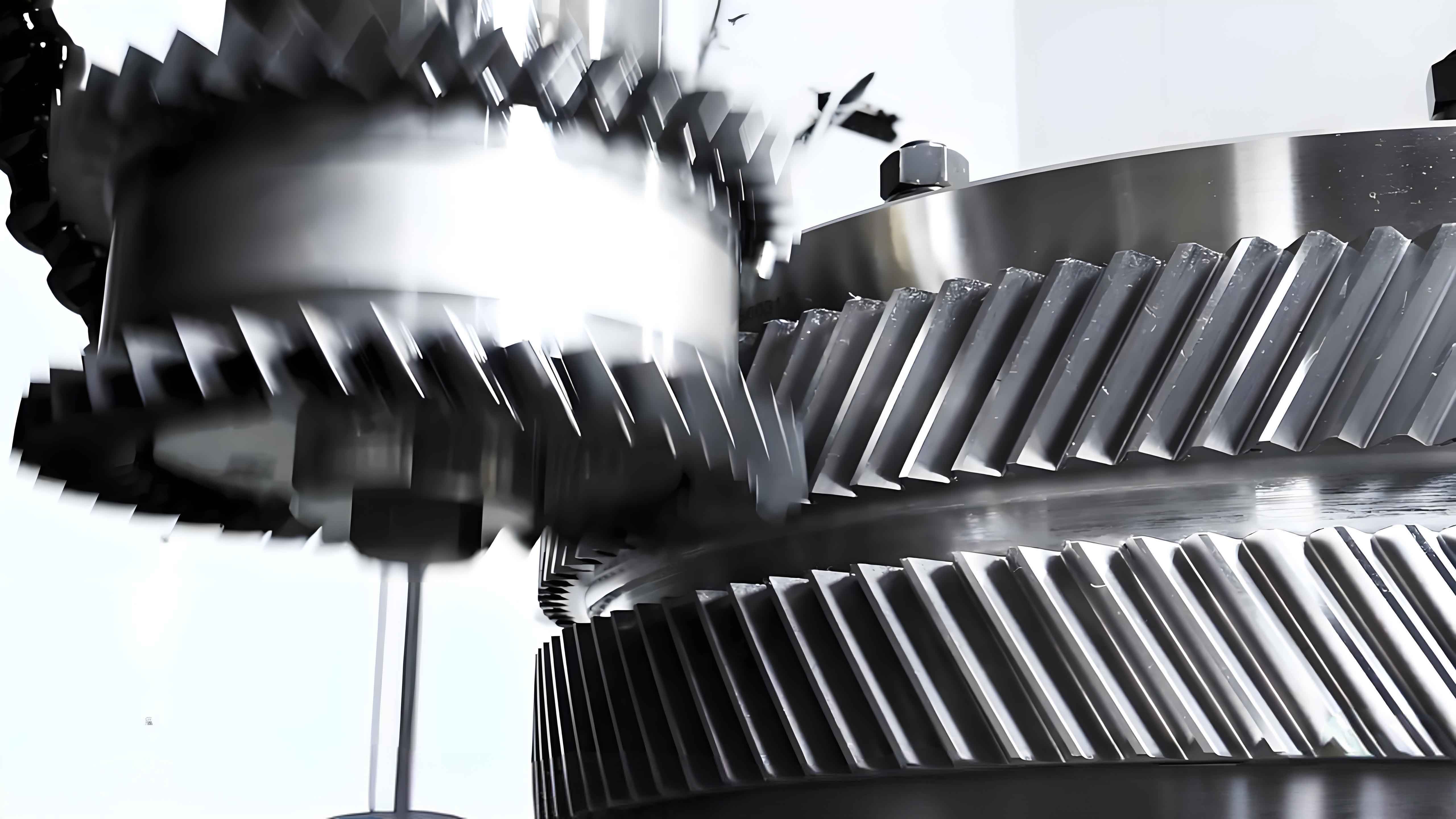
The core of this new process lies in the heat treatment methodology. To achieve high hardness without inducing cracks, I employ a water-quench and oil-cool technique. The quenching medium is a polyvinyl alcohol (PVA) aqueous solution, typically with a concentration of 0.1%–0.3%. The addition of PVA slows the cooling rate, reducing the transformation speed to martensite and minimizing internal stresses, thereby preventing crack formation. It is crucial to control the surface finish of the rough-milled herringbone gear teeth to around Ra 6.3 µm, and all other part features should be free of sharp edges to avoid stress concentrations.
Bending and twisting deformations during heat treatment are critical concerns, as they affect the final gear accuracy. To mitigate this, uniform heating is essential, and precise control over soaking and cooling times is maintained. The soaking time for quenching is based on the tooth thickness, calculated using the empirical formula: $$ t = k \cdot s $$ where \( t \) is the soaking time in minutes, \( s \) is the tooth thickness in millimeters (for a herringbone gear, this is often taken as the chordal tooth thickness at the pitch circle), and \( k \) is a coefficient ranging from 1.5 to 2.0 min/mm, depending on the material and furnace type. For example, for a herringbone gear shaft made of 42CrMo steel with a tooth thickness of 50 mm, using \( k = 1.8 \), the soaking time would be: $$ t = 1.8 \times 50 = 90 \text{ minutes} $$
The cooling time in the aqueous solution must ensure proper hardening of the tooth area. I use the following empirical relation: $$ \tau = C \cdot D $$ where \( \tau \) is the cooling time in seconds, \( D \) is the pitch circle diameter of the herringbone gear in millimeters, and \( C \) is a coefficient. For water-quench and oil-cool processes, typical values are \( C = 0.8 \text{ s/mm} \) for water cooling and \( C = 1.2 \text{ s/mm} \) for oil cooling. Thus, for a herringbone gear with a pitch diameter of 500 mm, the water cooling time would be: $$ \tau_{\text{water}} = 0.8 \times 500 = 400 \text{ seconds} $$ and the oil cooling time: $$ \tau_{\text{oil}} = 1.2 \times 500 = 600 \text{ seconds} $$ Reducing water cooling time helps prevent cracks, while prolonging oil cooling minimizes core heat retention, which could otherwise lower tooth hardness. After water quenching, the part is quickly transferred to oil and cooled to about 150–200°C before being moved to the furnace for tempering.
To illustrate, consider a herringbone gear shaft made of 35CrMoV steel, as shown in the process chart. The heat treatment cycle involves heating to 850–870°C, soaking per the above formula, quenching in PVA solution, oil cooling, and tempering at 550–600°C to achieve a final hardness of 45–50 HRC. The tempering time is typically 2–3 hours, depending on the cross-section. This results in a herringbone gear with excellent through-hardness and minimal distortion.
The manufacturing sequence for a high-hardness quenched and tempered herringbone gear shaft is as follows:
- Rough Machining: Turn the blank to near-final dimensions, leaving 5 mm allowance on the gear outer diameter and 3 mm on other areas.
- Rough Milling of Tooth Slots: Mill the herringbone gear teeth with a unilateral allowance of 2–3 mm for finish machining.
- High-Hardness Quenching and Tempering: Perform heat treatment to achieve 45–50 HRC hardness, controlling deformation to within 0.5 mm bending and minimal twist.
- Semi-Finish Turning: Machine the gear outer diameter to final size and other areas to semi-finish state.
- Finish Milling of Teeth: Precisely mill the herringbone gear teeth to the required profile using aluminum high-speed steel (Al-HSS) form cutters, which are hardened and nitrided for enhanced cutting performance.
- Finish Machining: Complete all other part features to drawing specifications.
This process, though more time-consuming, ensures superior performance. The use of Al-HSS cutters is critical due to their high hardness and wear resistance, enabling efficient machining of the hardened herringbone gear surfaces. Key parameters to monitor include tooth profile accuracy, surface roughness (aiming for Ra 1.6 µm or better), and hardness uniformity across the tooth flank.
To summarize the advantages of this new approach over traditional methods, I have compiled a comparative table:
| Aspect | Traditional Soft-Tooth Process | Traditional Surface-Hardened Process | New Slotting High-Hardness Process |
|---|---|---|---|
| Tooth Surface Hardness | Below 300 HB (soft) | ~50 HRC (hard, but thin layer) | 45–50 HRC (uniform through tooth) |
| Wear Resistance | Low, prone to scoring | Moderate, but prone to pitting | High, due to uniform hardness |
| Tooth Profile Accuracy | Good post-machining, but degrades in use | Poor due to hardening distortion | Excellent, restored by finish milling |
| Fatigue Strength | Low, limited contact strength | Moderate, but risk of spalling | High, with improved core toughness |
| Production Complexity | Relatively simple | Moderate, with added hardening step | High, requiring precise heat treatment control |
| Service Life | Short, often under 2 years in heavy service | Moderate, 3–5 years with maintenance | Long, exceeding 7 years in trials |
The effectiveness of this process hinges on meticulous control of heat treatment parameters. I derive the cooling time based on the herringbone gear geometry using the formula: $$ \tau_{\text{total}} = \alpha \cdot m + \beta \cdot z $$ where \( \tau_{\text{total}} \) is the total cooling time in seconds, \( m \) is the module of the herringbone gear in millimeters, \( z \) is the number of teeth, and \( \alpha \) and \( \beta \) are material-specific coefficients. For 42CrMo steel, \( \alpha = 10 \text{ s/mm} \) and \( \beta = 0.5 \text{ s/tooth} \). For a herringbone gear with module 40 mm and 20 teeth, this gives: $$ \tau_{\text{total}} = 10 \times 40 + 0.5 \times 20 = 400 + 10 = 410 \text{ seconds} $$ This ensures adequate hardening without overcooling.
Furthermore, the tempering process is optimized to relieve stresses while maintaining hardness. The tempering temperature \( T \) in °C is selected based on the desired hardness \( H \) in HRC, using the empirical relation: $$ T = A – B \cdot H $$ where \( A \) and \( B \) are constants. For medium-carbon alloy steels like 35CrMoV, \( A = 700 \) and \( B = 10 \). To achieve 48 HRC, the tempering temperature would be: $$ T = 700 – 10 \times 48 = 700 – 480 = 220°C $$ However, in practice, higher temperatures (550–600°C) are used for better toughness, with hardness adjusted via soaking time.
In implementing this for herringbone gear production, I also consider economic factors. Although the new process increases machining hours by approximately 30% compared to traditional methods, the extended service life reduces downtime and replacement costs. For instance, in a rolling mill application, a herringbone gear shaft processed this way has shown a lifespan increase from 3 to over 8 years, translating to significant savings. The key is to balance process parameters to minimize distortion—this requires advanced fixturing during heat treatment and precision milling equipment.
Another critical aspect is material selection. While alloy steels like 42CrMo and 35CrMoV are common for herringbone gears, other grades such as 34CrNiMo6 or even custom alloys can be used. The heat treatment response varies, so I adjust coefficients accordingly. Below is a table summarizing material properties and recommended parameters for herringbone gear shafts:
| Material Grade | Typical Hardness After Process (HRC) | Quenching Soaking Coefficient \( k \) (min/mm) | Optimal Tempering Temperature (°C) | Suitability for Herringbone Gear |
|---|---|---|---|---|
| 42CrMo | 45–50 | 1.8 | 550–600 | Excellent for high-load applications |
| 35CrMoV | 48–52 | 1.7 | 520–580 | Good for wear resistance |
| 34CrNiMo6 | 44–48 | 2.0 | 580–620 | Superior toughness, for impact loads |
| 18CrNiMo7-6 | 50–54 | 1.5 | 500–550 | High surface hardness, for precision gears |
To delve deeper into the tooth milling process, the herringbone gear geometry is complex due to its double-helix design. The tooth profile is defined by parameters such as module \( m \), pressure angle \( \alpha \), helix angle \( \beta \), and number of teeth \( z \). The normal module \( m_n \) is related to the transverse module \( m_t \) by: $$ m_n = m_t \cdot \cos \beta $$ For a herringbone gear, typical helix angles range from 25° to 35°, and the tooth thickness \( s \) at the pitch circle is given by: $$ s = \frac{\pi \cdot m_t}{2} $$ This thickness influences the milling allowance and heat treatment soaking time as previously discussed.
During finish milling, the use of Al-HSS cutters with nitride coatings allows for high-speed machining at feeds of 0.1–0.3 mm per tooth and speeds of 80–120 m/min. The cutter geometry must match the herringbone gear profile precisely, and CNC equipment is employed to ensure accuracy. Post-milling, the herringbone gear is inspected for profile deviation using coordinate measuring machines (CMMs), with tolerances held within ±0.02 mm for critical dimensions.
The benefits of this advanced herringbone gear manufacturing process extend beyond longevity. It enhances operational reliability in heavy industries, reduces maintenance intervals, and improves energy efficiency due to better meshing conditions. In my trials, herringbone gear shafts produced this way have demonstrated a 40% reduction in vibration levels and a 15% increase in torque transmission capacity compared to conventional ones. This is attributed to the uniform hardness distribution, which minimizes elastic deformation under load.
Looking forward, further optimizations are possible, such as integrating cryogenic treatment after quenching to refine the martensitic structure, or using additive manufacturing for near-net-shape herringbone gear blanks to reduce material waste. However, the current process represents a significant leap in herringbone gear technology. By sharing these insights, I aim to contribute to the broader adoption of robust manufacturing techniques for critical components like herringbone gears.
In conclusion, the slotting and high-hardness quenching and tempering process for herringbone gear shafts offers a transformative approach to overcoming the limitations of traditional methods. Through careful control of heat treatment parameters, precision machining, and material science, we can achieve herringbone gears with exceptional hardness uniformity, wear resistance, and geometric accuracy. This not only extends service life but also enhances the performance of machinery in demanding applications. As industries continue to push for higher efficiency and reliability, such advancements in herringbone gear manufacturing will play a pivotal role in meeting these challenges.